Manual
Page 3
... prior notice. For product-related information, check on our website at: http://www.gigabyte.com Identifying Your Motherboard Revision The revision number on your motherboard revision before updating motherboard BIOS, drivers, or when looking for technical information. Changes to their respective owners....the specifications and features in this manual may be made by any form or by GIGABYTE without GIGABYTE's prior written permission. All rights reserved. Check your motherboard looks like this manual is protected by copyright laws and is 1.0. The trademarks mentioned...
... prior notice. For product-related information, check on our website at: http://www.gigabyte.com Identifying Your Motherboard Revision The revision number on your motherboard revision before updating motherboard BIOS, drivers, or when looking for technical information. Changes to their respective owners....the specifications and features in this manual may be made by any form or by GIGABYTE without GIGABYTE's prior written permission. All rights reserved. Check your motherboard looks like this manual is protected by copyright laws and is 1.0. The trademarks mentioned...
Manual
Page 4
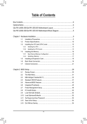
Table of Contents Box Contents...6 Optional Items...6 GA-P61-USB3-B3/GA-P61-DS3-B3 Motherboard Layout 7 GA-P61-USB3-B3/GA-P61-DS3-B3 Motherboard Block Diagram 8 Chapter 1 Hardware Installation 9 1-1 Installation Precautions 9 1-2 Product Specifications 10 1-3 Installing the CPU and CPU Cooler 13 1-3-1 Installing the CPU 13 1-3-2 Installing the CPU Cooler ...
Table of Contents Box Contents...6 Optional Items...6 GA-P61-USB3-B3/GA-P61-DS3-B3 Motherboard Layout 7 GA-P61-USB3-B3/GA-P61-DS3-B3 Motherboard Block Diagram 8 Chapter 1 Hardware Installation 9 1-1 Installation Precautions 9 1-2 Product Specifications 10 1-3 Installing the CPU and CPU Cooler 13 1-3-1 Installing the CPU 13 1-3-2 Installing the CPU Cooler ...
Manual
Page 6
Box Contents GA-P61-USB3-B3 or GA-P61-DS3-B3 motherboard Motherboard driver disk User's Manual Quick Installation Guide Two SATA cables I/O Shield The box contents above are subject to change without notice. The box contents are for reference only and the actual items shall depend on the product package you obtain. Optional Items 2-port USB 2.0 bracket (Part No. 12CR1-1UB030-5*R) 2-port SATA power cable (Part No. 12CF1-2SERPW-0*R) - 6 -
Box Contents GA-P61-USB3-B3 or GA-P61-DS3-B3 motherboard Motherboard driver disk User's Manual Quick Installation Guide Two SATA cables I/O Shield The box contents above are subject to change without notice. The box contents are for reference only and the actual items shall depend on the product package you obtain. Optional Items 2-port USB 2.0 bracket (Part No. 12CR1-1UB030-5*R) 2-port SATA power cable (Part No. 12CF1-2SERPW-0*R) - 6 -
Manual
Page 7
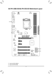
k Only for GA-P61-USB3-B3. GA-P61-USB3-B3/GA-P61-DS3-B3 Motherboard Layout KB_MS_USB ATX_12V CPU_FAN COMA LPT COAXIAL LGA1155 R_USB30j ATX R_USB20k DDR3_1 DDR3_2 USB_LAN AUDIO F_AUDIO Etron EJ168j SYS_FAN1 PWR_FAN PCIEX16 BAT GA-P61-USB3-B3/ GA-P61-DS3-B3 Realtek RTL8111E PCIEX1_1 CODEC PCIEX1_2 Intel® H61 SPDIF_O PCI1 SATA2_2 SATA2_3 SATA2_0 SATA2_1 iTE IT8728 PCI2 PCI3 SYS_FAN2 F_USB2 F_USB1 PCIe to PCI Bridge M_BIOS B_BIOS CLR_CMOS F_PANEL j Only for GA-P61-DS3-B3. - 7 -
k Only for GA-P61-USB3-B3. GA-P61-USB3-B3/GA-P61-DS3-B3 Motherboard Layout KB_MS_USB ATX_12V CPU_FAN COMA LPT COAXIAL LGA1155 R_USB30j ATX R_USB20k DDR3_1 DDR3_2 USB_LAN AUDIO F_AUDIO Etron EJ168j SYS_FAN1 PWR_FAN PCIEX16 BAT GA-P61-USB3-B3/ GA-P61-DS3-B3 Realtek RTL8111E PCIEX1_1 CODEC PCIEX1_2 Intel® H61 SPDIF_O PCI1 SATA2_2 SATA2_3 SATA2_0 SATA2_1 iTE IT8728 PCI2 PCI3 SYS_FAN2 F_USB2 F_USB1 PCIe to PCI Bridge M_BIOS B_BIOS CLR_CMOS F_PANEL j Only for GA-P61-DS3-B3. - 7 -
Manual
Page 8
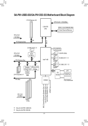
k Only for GA-P61-USB3-B3. GA-P61-USB3-B3/GA-P61-DS3-B3 Motherboard Block Diagram 1 PCI Express x16 CPU CLK+/- (100 MHz) LGA1155 CPU DDR3 1333/1066/800 MHz Dual Channel Memory PCIe CLK (100 MHz) x16 PCI .../Mouse MIC (Center/Subwoofer Speaker Out) Line Out (Front Speaker Out) Line In (Rear Speaker Out) S/PDIF Out PCI CLK (33 MHz) 3 PCI j Only for GA-P61-DS3-B3. - 8 -
k Only for GA-P61-USB3-B3. GA-P61-USB3-B3/GA-P61-DS3-B3 Motherboard Block Diagram 1 PCI Express x16 CPU CLK+/- (100 MHz) LGA1155 CPU DDR3 1333/1066/800 MHz Dual Channel Memory PCIe CLK (100 MHz) x16 PCI .../Mouse MIC (Center/Subwoofer Speaker Out) Line Out (Front Speaker Out) Line In (Rear Speaker Out) S/PDIF Out PCI CLK (33 MHz) 3 PCI j Only for GA-P61-DS3-B3. - 8 -
Manual
Page 9
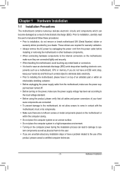
... turned off. •• Before turning on the power, make sure they are no leftover screws or metal components placed on the motherboard or within the computer casing. •• Do not place the computer system on the computer power during the installation process can become...required for warranty validation. •• Always remove the AC power by your hardware components are connected. •• To prevent damage to the motherboard, do not allow screws to come in a high-temperature environment. •• Turning on an uneven surface. •• Do not place...
... turned off. •• Before turning on the power, make sure they are no leftover screws or metal components placed on the motherboard or within the computer casing. •• Do not place the computer system on the computer power during the installation process can become...required for warranty validation. •• Always remove the AC power by your hardware components are connected. •• To prevent damage to the motherboard, do not allow screws to come in a high-temperature environment. •• Turning on an uneven surface. •• Do not place...
Manual
Page 12
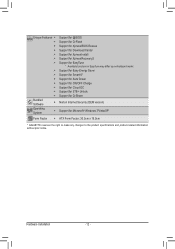
...138; Support for Xpress Install ŠŠ Support for Xpress Recovery2 ŠŠ Support for EasyTune * Available functions in EasyTune may differ by motherboard model. ŠŠ Support for Easy Energy Saver ŠŠ Support for Smart 6™ ŠŠ Support for Auto Green ŠŠ...138;Š Support for Microsoft® Windows 7/Vista/XP Form Factor ŠŠ ATX Form Factor; 30.5cm x 19.0cm * GIGABYTE reserves the right to make any changes to the product specifications and product-related information without prior notice. Hardware Installation - 12 -
...138; Support for Xpress Install ŠŠ Support for Xpress Recovery2 ŠŠ Support for EasyTune * Available functions in EasyTune may differ by motherboard model. ŠŠ Support for Easy Energy Saver ŠŠ Support for Smart 6™ ŠŠ Support for Auto Green ŠŠ...138;Š Support for Microsoft® Windows 7/Vista/XP Form Factor ŠŠ ATX Form Factor; 30.5cm x 19.0cm * GIGABYTE reserves the right to make any changes to the product specifications and product-related information without prior notice. Hardware Installation - 12 -
Manual
Page 13
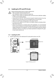
... list.) •• Always turn on the CPU. Locate the alignment keys on the motherboard CPU socket and the notches on the computer if the CPU cooler is not recommended that the motherboard supports the CPU. (Go to GIGABYTE's website for the peripherals. The CPU cannot be inserted if oriented incorrectly. (Or you...
... list.) •• Always turn on the CPU. Locate the alignment keys on the motherboard CPU socket and the notches on the computer if the CPU cooler is not recommended that the motherboard supports the CPU. (Go to GIGABYTE's website for the peripherals. The CPU cannot be inserted if oriented incorrectly. (Or you...
Manual
Page 14
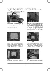
... the socket cover and use the other to correctly install the CPU into its locked position. Step 5: Push the CPU socket lever back into the motherboard CPU socket. Follow the steps below to lightly replace the load plate. Step 4: Once the CPU is under the shoulder screw. NOTE: Hold the CPU...
... the socket cover and use the other to correctly install the CPU into its locked position. Step 5: Push the CPU socket lever back into the motherboard CPU socket. Follow the steps below to lightly replace the load plate. Step 4: Once the CPU is under the shoulder screw. NOTE: Hold the CPU...
Manual
Page 15
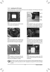
... sign on the male push pin. (Turning the push pin along the direction of the CPU cooler to the CPU fan header (CPU_FAN) on the motherboard. Step 6: Finally, attach the power connector of arrow is to remove the cooler, on the contrary, is to install.) Step 3: Place the cooler atop the... CPU, aligning the four push pins through the pin holes on the motherboard. Step 4: You should hear a "click" when pushing down on the push pins diagonally. Check that the Male and Female push pins are joined closely. (Refer...
... sign on the male push pin. (Turning the push pin along the direction of the CPU cooler to the CPU fan header (CPU_FAN) on the motherboard. Step 6: Finally, attach the power connector of arrow is to remove the cooler, on the contrary, is to install.) Step 3: Place the cooler atop the... CPU, aligning the four push pins through the pin holes on the motherboard. Step 4: You should hear a "click" when pushing down on the push pins diagonally. Check that the Male and Female push pins are joined closely. (Refer...
Manual
Page 16
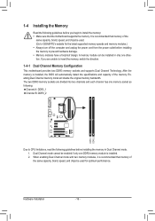
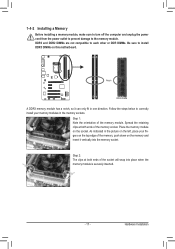
... the original memory bandwidth. If you begin to insert the memory, switch the direction. 1-4-1 Dual Channel Memory Configuration This motherboard provides two DDR3 memory sockets and supports Dual Channel Technology. Enabling Dual Channel memory mode will automatically detect the specifications and capacity... Channel B: DDR3_2 DDR3_1 DDR3_2 Due to CPU limitations, read the following guidelines before installing the memory to GIGABYTE's website for optimum performance. Hardware Installation - 16 - After the memory is recommended that the motherboard supports the memory.
... the original memory bandwidth. If you begin to insert the memory, switch the direction. 1-4-1 Dual Channel Memory Configuration This motherboard provides two DDR3 memory sockets and supports Dual Channel Technology. Enabling Dual Channel memory mode will automatically detect the specifications and capacity... Channel B: DDR3_2 DDR3_1 DDR3_2 Due to CPU limitations, read the following guidelines before installing the memory to GIGABYTE's website for optimum performance. Hardware Installation - 16 - After the memory is recommended that the motherboard supports the memory.
Manual
Page 17
... memory module has a notch, so it vertically into place when the memory module is securely inserted. - 17 - Hardware Installation Place the memory module on this motherboard.
... memory module has a notch, so it vertically into place when the memory module is securely inserted. - 17 - Hardware Installation Place the memory module on this motherboard.
Manual
Page 18
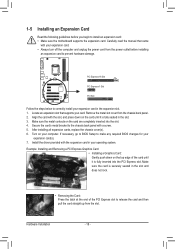
... turn off the computer and unplug the power cord from the power outlet before you begin to install an expansion card: • Make sure the motherboard supports the expansion card. Example: Installing and Removing a PCI Express Graphics Card: • Installing a Graphics Card: Gently push down on the top edge of the...
... turn off the computer and unplug the power cord from the power outlet before you begin to install an expansion card: • Make sure the motherboard supports the expansion card. Example: Installing and Removing a PCI Express Graphics Card: • Installing a Graphics Card: Gently push down on the top edge of the...
Manual
Page 19
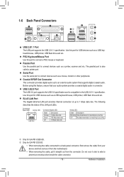
...to a back panel connector, first remove the cable from your audio system provides a coaxial digital audio in connector. Before using this port for GA-P61-DS3-B3. •• When removing the cable connected to connect a PS/2 mouse or keyboard. Connection/ Speed LED Activity LED LAN Port Connection/Speed... S/PDIF Out Connector This connector provides digital audio out to an external audio system that your device and then remove it from the motherboard. •• When removing the cable, pull it side to side to the USB 2.0/1.1 specification. RJ-45 LAN Port The Gigabit...
...to a back panel connector, first remove the cable from your audio system provides a coaxial digital audio in connector. Before using this port for GA-P61-DS3-B3. •• When removing the cable connected to connect a PS/2 mouse or keyboard. Connection/ Speed LED Activity LED LAN Port Connection/Speed... S/PDIF Out Connector This connector provides digital audio out to an external audio system that your device and then remove it from the motherboard. •• When removing the cable, pull it side to side to the USB 2.0/1.1 specification. RJ-45 LAN Port The Gigabit...
Manual
Page 21
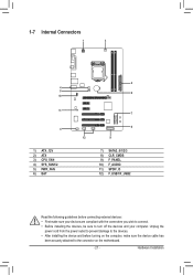
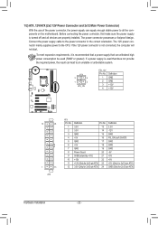
... and your devices are compliant with the connectors you wish to connect. •• Before installing the devices, be sure to the connector on the motherboard. - 21 - 1-7 Internal Connectors 1 3 4 5 10 11 4 1) ATX_12V 2) ATX 3) CPU_FAN 4) SYS_FAN1/2 5) PWR_FAN 6) BAT 2 6 7 8 12 9 7) SATA2_0/1/2/3 8) CLR_CMOS 9) F_PANEL 10) F_AUDIO 11) SPDIF_O 12) F_USB1/F_USB2 Read the following...
... and your devices are compliant with the connectors you wish to connect. •• Before installing the devices, be sure to the connector on the motherboard. - 21 - 1-7 Internal Connectors 1 3 4 5 10 11 4 1) ATX_12V 2) ATX 3) CPU_FAN 4) SYS_FAN1/2 5) PWR_FAN 6) BAT 2 6 7 8 12 9 7) SATA2_0/1/2/3 8) CLR_CMOS 9) F_PANEL 10) F_AUDIO 11) SPDIF_O 12) F_USB1/F_USB2 Read the following...
Manual
Page 22
...) Hardware Installation - 22 - Connect the power supply cable to the CPU. If the 12V power connector is turned off and all the components on the motherboard. 1/2) ATX_12V/ATX (2x2 12V Power Connector and 2x12 Main Power Connector) With the use of the power connector, the power supply can supply enough stable...
...) Hardware Installation - 22 - Connect the power supply cable to the CPU. If the 12V power connector is turned off and all the components on the motherboard. 1/2) ATX_12V/ATX (2x2 12V Power Connector and 2x12 Main Power Connector) With the use of the power connector, the power supply can supply enough stable...
Manual
Page 23
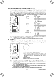
...the ground wire). You may be sure to prevent your computer and unplug the power cord. 222 Gently remove the battery from overheating. The motherboard supports CPU fan speed control, which requires the use a metal object like a screwdriver to keep the values (such as BIOS configurations, date... should face up). •• Used batteries must be installed inside the chassis. 3/4/5) CPU_FAN/SYS_FAN1/SYS_FAN2/PWR_FAN (Fan Headers) The motherboard has a 4-pin CPU fan header (CPU_FAN), a 4-pin (SYS_FAN2) and a 3-pin (SYS_FAN1) system fan headers, and a 3-pin power fan header (PWR_FAN...
...the ground wire). You may be sure to prevent your computer and unplug the power cord. 222 Gently remove the battery from overheating. The motherboard supports CPU fan speed control, which requires the use a metal object like a screwdriver to keep the values (such as BIOS configurations, date... should face up). •• Used batteries must be installed inside the chassis. 3/4/5) CPU_FAN/SYS_FAN1/SYS_FAN2/PWR_FAN (Fan Headers) The motherboard has a 4-pin CPU fan header (CPU_FAN), a 4-pin (SYS_FAN2) and a 3-pin (SYS_FAN1) system fan headers, and a 3-pin power fan header (PWR_FAN...
Manual
Page 24
... PORT 7) SATA2_0/1/2/3 (SATA 3Gb/s Connectors) The SATA connectors conform to Chapter 2, "BIOS Setup," for a few seconds. Failure to do so may cause damage to the motherboard. •• After system restart, go to BIOS Setup to load factory defaults (select Load Optimized Defaults) or manually configure the BIOS settings (refer to...
... PORT 7) SATA2_0/1/2/3 (SATA 3Gb/s Connectors) The SATA connectors conform to Chapter 2, "BIOS Setup," for a few seconds. Failure to do so may cause damage to the motherboard. •• After system restart, go to BIOS Setup to load factory defaults (select Load Optimized Defaults) or manually configure the BIOS settings (refer to...

Manual
Page 26
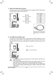
... connect an HDMI display to certain expansion cards like graphics cards and sound cards. Incorrect connection between the module connector and the motherboard header will be present on each wire instead of a single plug. For information about connecting the front panel audio module that ...has separated connectors on both of the motherboard header. If you to use a S/PDIF digital audio cable for digital audio output from your motherboard to the graphics card and have digital audio output from your motherboard to your chassis front panel audio module to Chapter ...
... connect an HDMI display to certain expansion cards like graphics cards and sound cards. Incorrect connection between the module connector and the motherboard header will be present on each wire instead of a single plug. For information about connecting the front panel audio module that ...has separated connectors on both of the motherboard header. If you to use a S/PDIF digital audio cable for digital audio output from your motherboard to the graphics card and have digital audio output from your motherboard to your chassis front panel audio module to Chapter ...
Manual
Page 29
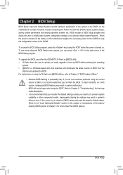
... how to quickly and easily upgrade or back up BIOS without entering the operating system. •• @BIOS is turned off, the battery on the motherboard. Chapter 2 BIOS Setup BIOS (Basic Input and Output System) records hardware parameters of the system in the CMOS on the... see more advanced BIOS Setup menu options, you need to) to prevent system instability or other unexpected results. To upgrade the BIOS, use either the GIGABYTE Q-Flash or @BIOS utility. •• Q-Flash allows the user to clear the CMOS values.) - 29 - To flash the BIOS, do not encounter problems using...
... how to quickly and easily upgrade or back up BIOS without entering the operating system. •• @BIOS is turned off, the battery on the motherboard. Chapter 2 BIOS Setup BIOS (Basic Input and Output System) records hardware parameters of the system in the CMOS on the... see more advanced BIOS Setup menu options, you need to) to prevent system instability or other unexpected results. To upgrade the BIOS, use either the GIGABYTE Q-Flash or @BIOS utility. •• Q-Flash allows the user to clear the CMOS values.) - 29 - To flash the BIOS, do not encounter problems using...


