Manual
Page 3
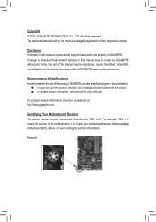
...in this manual may be made by GIGABYTE without GIGABYTE's prior written permission. For product-related information, check on our website at: http://www.gigabyte.com Identifying Your Motherboard Revision The revision number on your motherboard revision before updating motherboard BIOS, drivers, or when looking ...order to their respective owners. For example, "REV: 1.0" means the revision of GIGABYTE. The trademarks mentioned in any form or by copyright laws and is the property of the motherboard is protected by any means without prior notice. Copyright © 2011 GIGA-BYTE...
...in this manual may be made by GIGABYTE without GIGABYTE's prior written permission. For product-related information, check on our website at: http://www.gigabyte.com Identifying Your Motherboard Revision The revision number on your motherboard revision before updating motherboard BIOS, drivers, or when looking ...order to their respective owners. For example, "REV: 1.0" means the revision of GIGABYTE. The trademarks mentioned in any form or by copyright laws and is the property of the motherboard is protected by any means without prior notice. Copyright © 2011 GIGA-BYTE...
Manual
Page 4
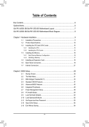
Table of Contents Box Contents...6 Optional Items...6 GA-P61-USB3-B3/GA-P61-DS3-B3 Motherboard Layout 7 GA-P61-USB3-B3/GA-P61-DS3-B3 Motherboard Block Diagram 8 Chapter 1 Hardware Installation 9 1-1 Installation Precautions 9 1-2 Product Specifications 10 1-3 Installing the CPU and CPU Cooler 13 1-3-1 Installing the CPU 13 1-3-2 Installing the CPU Cooler ...
Table of Contents Box Contents...6 Optional Items...6 GA-P61-USB3-B3/GA-P61-DS3-B3 Motherboard Layout 7 GA-P61-USB3-B3/GA-P61-DS3-B3 Motherboard Block Diagram 8 Chapter 1 Hardware Installation 9 1-1 Installation Precautions 9 1-2 Product Specifications 10 1-3 Installing the CPU and CPU Cooler 13 1-3-1 Installing the CPU 13 1-3-2 Installing the CPU Cooler ...
Manual
Page 6
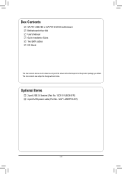
The box contents are for reference only and the actual items shall depend on the product package you obtain. Box Contents GA-P61-USB3-B3 or GA-P61-DS3-B3 motherboard Motherboard driver disk User's Manual Quick Installation Guide Two SATA cables I/O Shield The box contents above are subject to change without notice. Optional Items 2-port USB 2.0 bracket (Part No. 12CR1-1UB030-5*R) 2-port SATA power cable (Part No. 12CF1-2SERPW-0*R) - 6 -
The box contents are for reference only and the actual items shall depend on the product package you obtain. Box Contents GA-P61-USB3-B3 or GA-P61-DS3-B3 motherboard Motherboard driver disk User's Manual Quick Installation Guide Two SATA cables I/O Shield The box contents above are subject to change without notice. Optional Items 2-port USB 2.0 bracket (Part No. 12CR1-1UB030-5*R) 2-port SATA power cable (Part No. 12CF1-2SERPW-0*R) - 6 -
Manual
Page 7
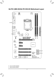
k Only for GA-P61-USB3-B3. GA-P61-USB3-B3/GA-P61-DS3-B3 Motherboard Layout KB_MS_USB ATX_12V CPU_FAN COMA LPT COAXIAL LGA1155 R_USB30j ATX R_USB20k DDR3_1 DDR3_2 USB_LAN AUDIO F_AUDIO Etron EJ168j SYS_FAN1 PWR_FAN PCIEX16 BAT GA-P61-USB3-B3/ GA-P61-DS3-B3 Realtek RTL8111E PCIEX1_1 CODEC PCIEX1_2 Intel® H61 SPDIF_O PCI1 SATA2_2 SATA2_3 SATA2_0 SATA2_1 iTE IT8728 PCI2 PCI3 SYS_FAN2 F_USB2 F_USB1 PCIe to PCI Bridge M_BIOS B_BIOS CLR_CMOS F_PANEL j Only for GA-P61-DS3-B3. - 7 -
k Only for GA-P61-USB3-B3. GA-P61-USB3-B3/GA-P61-DS3-B3 Motherboard Layout KB_MS_USB ATX_12V CPU_FAN COMA LPT COAXIAL LGA1155 R_USB30j ATX R_USB20k DDR3_1 DDR3_2 USB_LAN AUDIO F_AUDIO Etron EJ168j SYS_FAN1 PWR_FAN PCIEX16 BAT GA-P61-USB3-B3/ GA-P61-DS3-B3 Realtek RTL8111E PCIEX1_1 CODEC PCIEX1_2 Intel® H61 SPDIF_O PCI1 SATA2_2 SATA2_3 SATA2_0 SATA2_1 iTE IT8728 PCI2 PCI3 SYS_FAN2 F_USB2 F_USB1 PCIe to PCI Bridge M_BIOS B_BIOS CLR_CMOS F_PANEL j Only for GA-P61-DS3-B3. - 7 -
Manual
Page 8
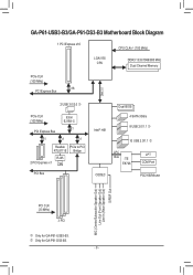
k Only for GA-P61-USB3-B3. GA-P61-USB3-B3/GA-P61-DS3-B3 Motherboard Block Diagram 1 PCI Express x16 CPU CLK+/- (100 MHz) LGA1155 CPU DDR3 1333/1066/800 MHz Dual Channel Memory PCIe CLK (100 MHz) x16 PCI .../Mouse MIC (Center/Subwoofer Speaker Out) Line Out (Front Speaker Out) Line In (Rear Speaker Out) S/PDIF Out PCI CLK (33 MHz) 3 PCI j Only for GA-P61-DS3-B3. - 8 -
k Only for GA-P61-USB3-B3. GA-P61-USB3-B3/GA-P61-DS3-B3 Motherboard Block Diagram 1 PCI Express x16 CPU CLK+/- (100 MHz) LGA1155 CPU DDR3 1333/1066/800 MHz Dual Channel Memory PCIe CLK (100 MHz) x16 PCI .../Mouse MIC (Center/Subwoofer Speaker Out) Line Out (Front Speaker Out) Line In (Rear Speaker Out) S/PDIF Out PCI CLK (33 MHz) 3 PCI j Only for GA-P61-DS3-B3. - 8 -
Manual
Page 9
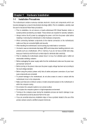
...power connectors of the product, please consult a certified computer technician. - 9 - ponents such as a motherboard, CPU or memory. Chapter 1 Hardware Installation 1-1 Installation Precautions The motherboard contains numerous delicate electronic circuits and components which can lead to damage to system components as well as physical...strap, keep your hands dry and first touch a metal object to eliminate static electricity. •• Prior to installing the motherboard, please have it on top of an antistatic pad or within the computer casing. •• Do not place the computer...
...power connectors of the product, please consult a certified computer technician. - 9 - ponents such as a motherboard, CPU or memory. Chapter 1 Hardware Installation 1-1 Installation Precautions The motherboard contains numerous delicate electronic circuits and components which can lead to damage to system components as well as physical...strap, keep your hands dry and first touch a metal object to eliminate static electricity. •• Prior to installing the motherboard, please have it on top of an antistatic pad or within the computer casing. •• Do not place the computer...
Manual
Page 12
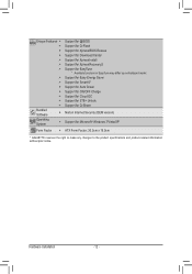
...ŠŠ Support for Xpress Install ŠŠ Support for Xpress Recovery2 ŠŠ Support for EasyTune * Available functions in EasyTune may differ by motherboard model. ŠŠ Support for Easy Energy Saver ŠŠ Support for Smart 6™ ŠŠ Support for Auto Green ŠŠ ... Operating System ŠŠ Support for Microsoft® Windows 7/Vista/XP Form Factor ŠŠ ATX Form Factor; 30.5cm x 19.0cm * GIGABYTE reserves the right to make any changes to the product specifications and product-related information without prior notice.
...ŠŠ Support for Xpress Install ŠŠ Support for Xpress Recovery2 ŠŠ Support for EasyTune * Available functions in EasyTune may differ by motherboard model. ŠŠ Support for Easy Energy Saver ŠŠ Support for Smart 6™ ŠŠ Support for Auto Green ŠŠ ... Operating System ŠŠ Support for Microsoft® Windows 7/Vista/XP Form Factor ŠŠ ATX Form Factor; 30.5cm x 19.0cm * GIGABYTE reserves the right to make any changes to the product specifications and product-related information without prior notice.
Manual
Page 13
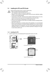
It is not recommended that the motherboard supports the CPU. (Go to GIGABYTE's website for the latest CPU support list.) •• Always turn on the surface of the CPU. •• Do not turn off the computer ... cannot be set the frequency beyond hardware specifications since it does not meet the standard requirements for the peripherals. Locate the alignment keys on the motherboard CPU socket and the notches on the CPU - 13 - age of the CPU may locate the notches on both sides of the CPU and alignment...
It is not recommended that the motherboard supports the CPU. (Go to GIGABYTE's website for the latest CPU support list.) •• Always turn on the surface of the CPU. •• Do not turn off the computer ... cannot be set the frequency beyond hardware specifications since it does not meet the standard requirements for the peripherals. Locate the alignment keys on the motherboard CPU socket and the notches on the CPU - 13 - age of the CPU may locate the notches on both sides of the CPU and alignment...
Manual
Page 14
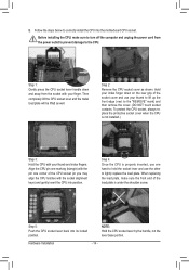
... properly inserted, use one corner of the socket cover and use the other to the CPU. Step 5: Push the CPU socket lever back into the motherboard CPU socket. Follow the steps below to the "REMOVE" mark) and then remove the cover. (DO NOT touch socket contacts. Step 1: Gently press the CPU...
... properly inserted, use one corner of the socket cover and use the other to the CPU. Step 5: Push the CPU socket lever back into the motherboard CPU socket. Follow the steps below to the "REMOVE" mark) and then remove the cover. (DO NOT touch socket contacts. Step 1: Gently press the CPU...
Manual
Page 15
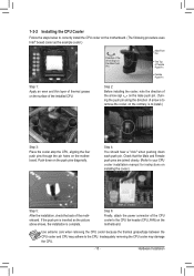
...grease on the surface of the CPU cooler to the CPU fan header (CPU_FAN) on the motherboard. 1-3-2 Installing the CPU Cooler Follow the steps below to correctly install the CPU cooler on the motherboard. (The following procedure uses Intel® boxed cooler as the picture above shows, the ...pin holes on the male push pin. (Turning the push pin along the direction of the motherboard. Step 2: Before installing the cooler, note the direction of the arrow sign on the motherboard. Use extreme care when removing the CPU cooler because the thermal grease/tape between the CPU cooler...
...grease on the surface of the CPU cooler to the CPU fan header (CPU_FAN) on the motherboard. 1-3-2 Installing the CPU Cooler Follow the steps below to correctly install the CPU cooler on the motherboard. (The following procedure uses Intel® boxed cooler as the picture above shows, the ...pin holes on the male push pin. (Turning the push pin along the direction of the motherboard. Step 2: Before installing the cooler, note the direction of the arrow sign on the motherboard. Use extreme care when removing the CPU cooler because the thermal grease/tape between the CPU cooler...
Manual
Page 16
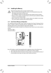
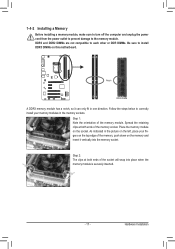
.... The two DDR3 memory sockets are unable to insert the memory, switch the direction. 1-4-1 Dual Channel Memory Configuration This motherboard provides two DDR3 memory sockets and supports Dual Channel Technology. If you begin to install the memory: •• Make sure that ...Channel memory mode will automatically detect the specifications and capacity of the same capacity, brand, speed, and chips be used. (Go to GIGABYTE's website for optimum performance. 1-4 Installing the Memory Read the following guidelines before you are divided into two channels and each channel has ...
.... The two DDR3 memory sockets are unable to insert the memory, switch the direction. 1-4-1 Dual Channel Memory Configuration This motherboard provides two DDR3 memory sockets and supports Dual Channel Technology. If you begin to install the memory: •• Make sure that ...Channel memory mode will automatically detect the specifications and capacity of the same capacity, brand, speed, and chips be used. (Go to GIGABYTE's website for optimum performance. 1-4 Installing the Memory Read the following guidelines before you are divided into two channels and each channel has ...
Manual
Page 17
..., make sure to turn off the computer and unplug the power cord from the power outlet to prevent damage to install DDR3 DIMMs on this motherboard. Follow the steps below to correctly install your memory modules in the picture on the left, place your fingers on the socket. As indicated in...
..., make sure to turn off the computer and unplug the power cord from the power outlet to prevent damage to install DDR3 DIMMs on this motherboard. Follow the steps below to correctly install your memory modules in the picture on the left, place your fingers on the socket. As indicated in...
Manual
Page 18
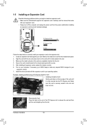
... the card and then pull the card straight up from the power outlet before you begin to install an expansion card: • Make sure the motherboard supports the expansion card. 1-5 Installing an Expansion Card Read the following guidelines before installing an expansion card to prevent hardware damage. Carefully read the manual...
... the card and then pull the card straight up from the power outlet before you begin to install an expansion card: • Make sure the motherboard supports the expansion card. 1-5 Installing an Expansion Card Read the following guidelines before installing an expansion card to prevent hardware damage. Carefully read the manual...
Manual
Page 19
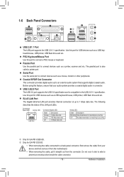
... for USB devices such as a USB keyboard/mouse, USB printer, USB flash drive and etc. PS/2 Keyboard/Mouse Port Use this port for GA-P61-DS3-B3. •• When removing the cable connected to an external audio system that your device and then remove it from the connector. Parallel Port ... Serial Port Use the serial port to prevent an electrical short inside the cable connector. - 19 - Do not rock it straight out from the motherboard. •• When removing the cable, pull it side to side to connect devices such as a printer, scanner and etc. Connection/ Speed ...
... for USB devices such as a USB keyboard/mouse, USB printer, USB flash drive and etc. PS/2 Keyboard/Mouse Port Use this port for GA-P61-DS3-B3. •• When removing the cable connected to an external audio system that your device and then remove it from the connector. Parallel Port ... Serial Port Use the serial port to prevent an electrical short inside the cable connector. - 19 - Do not rock it straight out from the motherboard. •• When removing the cable, pull it side to side to connect devices such as a printer, scanner and etc. Connection/ Speed ...
Manual
Page 21
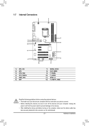
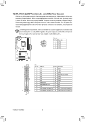
... 4 1) ATX_12V 2) ATX 3) CPU_FAN 4) SYS_FAN1/2 5) PWR_FAN 6) BAT 2 6 7 8 12 9 7) SATA2_0/1/2/3 8) CLR_CMOS 9) F_PANEL 10) F_AUDIO 11) SPDIF_O 12) F_USB1/F_USB2 Read the following guidelines before turning on the motherboard. - 21 -
... 4 1) ATX_12V 2) ATX 3) CPU_FAN 4) SYS_FAN1/2 5) PWR_FAN 6) BAT 2 6 7 8 12 9 7) SATA2_0/1/2/3 8) CLR_CMOS 9) F_PANEL 10) F_AUDIO 11) SPDIF_O 12) F_USB1/F_USB2 Read the following guidelines before turning on the motherboard. - 21 -
Manual
Page 22
... does not provide the required power, the result can lead to the CPU. If a power supply is turned off and all the components on the motherboard. Connect the power supply cable to all devices are properly installed. 1/2) ATX_12V/ATX (2x2 12V Power Connector and 2x12 Main Power Connector) With the use...
... does not provide the required power, the result can lead to the CPU. If a power supply is turned off and all the components on the motherboard. Connect the power supply cable to all devices are properly installed. 1/2) ATX_12V/ATX (2x2 12V Power Connector and 2x12 Main Power Connector) With the use...
Manual
Page 23
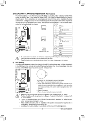
The motherboard supports CPU fan speed control, which requires the use a metal object like a screwdriver to the CPU or the system may result in damage to touch ... battery: 111 Turn off your computer and unplug the power cord. 222 Gently remove the battery from overheating. 3/4/5) CPU_FAN/SYS_FAN1/SYS_FAN2/PWR_FAN (Fan Headers) The motherboard has a 4-pin CPU fan header (CPU_FAN), a 4-pin (SYS_FAN2) and a 3-pin (SYS_FAN1) system fan headers, and a 3-pin power fan header (PWR_FAN). Most fan headers possess a foolproof...
The motherboard supports CPU fan speed control, which requires the use a metal object like a screwdriver to the CPU or the system may result in damage to touch ... battery: 111 Turn off your computer and unplug the power cord. 222 Gently remove the battery from overheating. 3/4/5) CPU_FAN/SYS_FAN1/SYS_FAN2/PWR_FAN (Fan Headers) The motherboard has a 4-pin CPU fan header (CPU_FAN), a 4-pin (SYS_FAN2) and a 3-pin (SYS_FAN1) system fan headers, and a 3-pin power fan header (PWR_FAN). Most fan headers possess a foolproof...
Manual
Page 24
... a few seconds. DEBUGDEBUG PORT PORT 7) SATA2_0/1/2/3 (SATA 3Gb/s Connectors) The SATA connectors conform to factory defaults. Failure to do so may cause damage to the motherboard. •• After system restart, go to BIOS Setup to load factory defaults (select Load Optimized Defaults) or manually configure the BIOS settings (refer to...
... a few seconds. DEBUGDEBUG PORT PORT 7) SATA2_0/1/2/3 (SATA 3Gb/s Connectors) The SATA connectors conform to factory defaults. Failure to do so may cause damage to the motherboard. •• After system restart, go to BIOS Setup to load factory defaults (select Load Optimized Defaults) or manually configure the BIOS settings (refer to...

Manual
Page 26
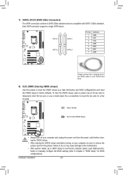
You may require you wish to connect an HDMI display to the graphics card and have digital audio output from your motherboard to certain expansion cards like graphics cards and sound cards. Definition 1 MIC2_L For AC'97 Front Panel Audio: Pin ... on both of the front and back panel audio connections simultaneously. Incorrect connection between the module connector and the motherboard header will be present on each wire instead of the motherboard header. Definition 1 1 SPDIFO 2 GND Hardware Installation - 26 - For information about connecting the S/PDIF digital...
You may require you wish to connect an HDMI display to the graphics card and have digital audio output from your motherboard to certain expansion cards like graphics cards and sound cards. Definition 1 MIC2_L For AC'97 Front Panel Audio: Pin ... on both of the front and back panel audio connections simultaneously. Incorrect connection between the module connector and the motherboard header will be present on each wire instead of the motherboard header. Definition 1 1 SPDIFO 2 GND Hardware Installation - 26 - For information about connecting the S/PDIF digital...
Manual
Page 29
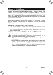
... press the key during system startup, saving system parameters and loading operating system, etc. BIOS Setup To upgrade the BIOS, use either the GIGABYTE Q-Flash or @BIOS utility. •• Q-Flash allows the user to quickly and easily upgrade or back up BIOS without entering the ...operating system. •• @BIOS is turned on the motherboard. Inadequately altering the settings may result in system malfunction. •• BIOS will emit a beep code during the POST. Its major functions...
... press the key during system startup, saving system parameters and loading operating system, etc. BIOS Setup To upgrade the BIOS, use either the GIGABYTE Q-Flash or @BIOS utility. •• Q-Flash allows the user to quickly and easily upgrade or back up BIOS without entering the ...operating system. •• @BIOS is turned on the motherboard. Inadequately altering the settings may result in system malfunction. •• BIOS will emit a beep code during the POST. Its major functions...


