Manual
Page 3
...assist in the use of this manual is protected by any means without prior notice. Check your motherboard looks like this manual may be made by GIGABYTE without GIGABYTE's prior written permission. Copyright © 2011 GIGA-BYTE TECHNOLOGY CO., LTD. All rights reserved...laws and is 1.0. For product-related information, check on our website at: http://www.gigabyte.com Identifying Your Motherboard Revision The revision number on your motherboard revision before updating motherboard BIOS, drivers, or when looking for technical information. Disclaimer Information in this manual may ...
...assist in the use of this manual is protected by any means without prior notice. Check your motherboard looks like this manual may be made by GIGABYTE without GIGABYTE's prior written permission. Copyright © 2011 GIGA-BYTE TECHNOLOGY CO., LTD. All rights reserved...laws and is 1.0. For product-related information, check on our website at: http://www.gigabyte.com Identifying Your Motherboard Revision The revision number on your motherboard revision before updating motherboard BIOS, drivers, or when looking for technical information. Disclaimer Information in this manual may ...
Manual
Page 4
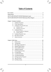
Table of Contents Box Contents...6 Optional Items...6 GA-P61-USB3-B3/GA-P61-DS3-B3 Motherboard Layout 7 GA-P61-USB3-B3/GA-P61-DS3-B3 Motherboard Block Diagram 8 Chapter 1 Hardware Installation 9 1-1 Installation Precautions 9 1-2 Product Specifications 10 1-3 Installing the CPU and CPU Cooler 13 1-3-1 Installing the CPU 13 1-3-2 Installing the CPU Cooler ...
Table of Contents Box Contents...6 Optional Items...6 GA-P61-USB3-B3/GA-P61-DS3-B3 Motherboard Layout 7 GA-P61-USB3-B3/GA-P61-DS3-B3 Motherboard Block Diagram 8 Chapter 1 Hardware Installation 9 1-1 Installation Precautions 9 1-2 Product Specifications 10 1-3 Installing the CPU and CPU Cooler 13 1-3-1 Installing the CPU 13 1-3-2 Installing the CPU Cooler ...
Manual
Page 6
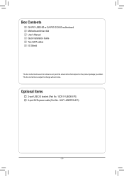
Optional Items 2-port USB 2.0 bracket (Part No. 12CR1-1UB030-5*R) 2-port SATA power cable (Part No. 12CF1-2SERPW-0*R) - 6 - The box contents are for reference only and the actual items shall depend on the product package you obtain. Box Contents GA-P61-USB3-B3 or GA-P61-DS3-B3 motherboard Motherboard driver disk User's Manual Quick Installation Guide Two SATA cables I/O Shield The box contents above are subject to change without notice.
Optional Items 2-port USB 2.0 bracket (Part No. 12CR1-1UB030-5*R) 2-port SATA power cable (Part No. 12CF1-2SERPW-0*R) - 6 - The box contents are for reference only and the actual items shall depend on the product package you obtain. Box Contents GA-P61-USB3-B3 or GA-P61-DS3-B3 motherboard Motherboard driver disk User's Manual Quick Installation Guide Two SATA cables I/O Shield The box contents above are subject to change without notice.
Manual
Page 7
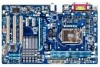
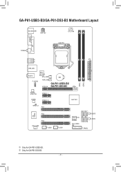
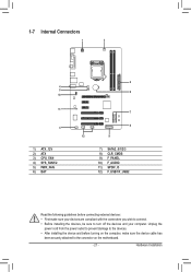
GA-P61-USB3-B3/GA-P61-DS3-B3 Motherboard Layout KB_MS_USB ATX_12V CPU_FAN COMA LPT COAXIAL LGA1155 R_USB30j ATX R_USB20k DDR3_1 DDR3_2 USB_LAN AUDIO F_AUDIO Etron EJ168j SYS_FAN1 PWR_FAN PCIEX16 BAT GA-P61-USB3-B3/ GA-P61-DS3-B3 Realtek RTL8111E PCIEX1_1 CODEC PCIEX1_2 Intel® H61 SPDIF_O PCI1 SATA2_2 SATA2_3 SATA2_0 SATA2_1 iTE IT8728 PCI2 PCI3 SYS_FAN2 F_USB2 F_USB1 PCIe to PCI Bridge M_BIOS B_BIOS CLR_CMOS F_PANEL j Only for GA-P61-DS3-B3. - 7 - k Only for GA-P61-USB3-B3.
GA-P61-USB3-B3/GA-P61-DS3-B3 Motherboard Layout KB_MS_USB ATX_12V CPU_FAN COMA LPT COAXIAL LGA1155 R_USB30j ATX R_USB20k DDR3_1 DDR3_2 USB_LAN AUDIO F_AUDIO Etron EJ168j SYS_FAN1 PWR_FAN PCIEX16 BAT GA-P61-USB3-B3/ GA-P61-DS3-B3 Realtek RTL8111E PCIEX1_1 CODEC PCIEX1_2 Intel® H61 SPDIF_O PCI1 SATA2_2 SATA2_3 SATA2_0 SATA2_1 iTE IT8728 PCI2 PCI3 SYS_FAN2 F_USB2 F_USB1 PCIe to PCI Bridge M_BIOS B_BIOS CLR_CMOS F_PANEL j Only for GA-P61-DS3-B3. - 7 - k Only for GA-P61-USB3-B3.
Manual
Page 8
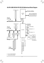
GA-P61-USB3-B3/GA-P61-DS3-B3 Motherboard Block Diagram 1 PCI Express x16 CPU CLK+/- (100 MHz) LGA1155 CPU DDR3 1333/1066/800 MHz Dual Channel Memory PCIe CLK (100 MHz) x16 PCI .../Mouse MIC (Center/Subwoofer Speaker Out) Line Out (Front Speaker Out) Line In (Rear Speaker Out) S/PDIF Out PCI CLK (33 MHz) 3 PCI j Only for GA-P61-DS3-B3. - 8 - k Only for GA-P61-USB3-B3.
GA-P61-USB3-B3/GA-P61-DS3-B3 Motherboard Block Diagram 1 PCI Express x16 CPU CLK+/- (100 MHz) LGA1155 CPU DDR3 1333/1066/800 MHz Dual Channel Memory PCIe CLK (100 MHz) x16 PCI .../Mouse MIC (Center/Subwoofer Speaker Out) Line Out (Front Speaker Out) Line In (Rear Speaker Out) S/PDIF Out PCI CLK (33 MHz) 3 PCI j Only for GA-P61-DS3-B3. - 8 - k Only for GA-P61-USB3-B3.
Manual
Page 9
... the product, please verify that all cables and power connectors of your dealer. Chapter 1 Hardware Installation 1-1 Installation Precautions The motherboard contains numerous delicate electronic circuits and components which can lead to damage to system components as well as physical harm to the ... system in a high-temperature environment. •• Turning on the computer power during the installation process can become damaged as a motherboard, CPU or memory. Prior to installation, carefully read the user's manual and follow these procedures: •• Prior to installation...
... the product, please verify that all cables and power connectors of your dealer. Chapter 1 Hardware Installation 1-1 Installation Precautions The motherboard contains numerous delicate electronic circuits and components which can lead to damage to system components as well as physical harm to the ... system in a high-temperature environment. •• Turning on the computer power during the installation process can become damaged as a motherboard, CPU or memory. Prior to installation, carefully read the user's manual and follow these procedures: •• Prior to installation...
Manual
Page 12
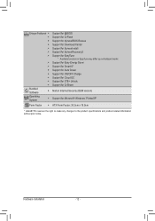
...ŠŠ Support for Xpress Install ŠŠ Support for Xpress Recovery2 ŠŠ Support for EasyTune * Available functions in EasyTune may differ by motherboard model. ŠŠ Support for Easy Energy Saver ŠŠ Support for Smart 6™ ŠŠ Support for Auto Green ŠŠ ... Operating System ŠŠ Support for Microsoft® Windows 7/Vista/XP Form Factor ŠŠ ATX Form Factor; 30.5cm x 19.0cm * GIGABYTE reserves the right to make any changes to the product specifications and product-related information without prior notice.
...ŠŠ Support for Xpress Install ŠŠ Support for Xpress Recovery2 ŠŠ Support for EasyTune * Available functions in EasyTune may differ by motherboard model. ŠŠ Support for Easy Energy Saver ŠŠ Support for Smart 6™ ŠŠ Support for Auto Green ŠŠ ... Operating System ŠŠ Support for Microsoft® Windows 7/Vista/XP Form Factor ŠŠ ATX Form Factor; 30.5cm x 19.0cm * GIGABYTE reserves the right to make any changes to the product specifications and product-related information without prior notice.
Manual
Page 13
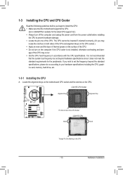
... CPU Notch Notch Triangle Pin One Marking on the CPU - 13 - It is not installed, otherwise overheating and dam- Locate the alignment keys on the motherboard CPU socket and the notches on the surface of the CPU may locate the notches on both sides of the CPU and alignment keys on... the peripherals. age of the CPU. •• Do not turn on the computer if the CPU cooler is not recommended that the motherboard supports the CPU. (Go to GIGABYTE's website for the latest CPU support list.) •• Always turn off the computer and unplug the power cord from the power...
... CPU Notch Notch Triangle Pin One Marking on the CPU - 13 - It is not installed, otherwise overheating and dam- Locate the alignment keys on the motherboard CPU socket and the notches on the surface of the CPU may locate the notches on both sides of the CPU and alignment keys on... the peripherals. age of the CPU. •• Do not turn on the computer if the CPU cooler is not recommended that the motherboard supports the CPU. (Go to GIGABYTE's website for the latest CPU support list.) •• Always turn off the computer and unplug the power cord from the power...
Manual
Page 14
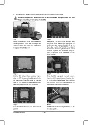
... prevent damage to the "REMOVE" mark) and then remove the cover. (DO NOT touch socket contacts. Step 5: Push the CPU socket lever back into the motherboard CPU socket. Step 4: Once the CPU is properly inserted, use one corner of the CPU socket (or you may align the CPU notches with your...
... prevent damage to the "REMOVE" mark) and then remove the cover. (DO NOT touch socket contacts. Step 5: Push the CPU socket lever back into the motherboard CPU socket. Step 4: Once the CPU is properly inserted, use one corner of the CPU socket (or you may align the CPU notches with your...
Manual
Page 15
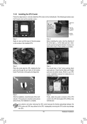
... cooler, on the contrary, is complete. 1-3-2 Installing the CPU Cooler Follow the steps below to the CPU fan header (CPU_FAN) on the motherboard. Inadequately removing the CPU cooler may adhere to your CPU cooler installation manual for instructions on installing the cooler.) Step 5: After the installation, ...on the male push pin. (Turning the push pin along the direction of the CPU cooler to correctly install the CPU cooler on the motherboard. (The following procedure uses Intel® boxed cooler as the picture above shows, the installation is to install.) Step 3: Place the ...
... cooler, on the contrary, is complete. 1-3-2 Installing the CPU Cooler Follow the steps below to the CPU fan header (CPU_FAN) on the motherboard. Inadequately removing the CPU cooler may adhere to your CPU cooler installation manual for instructions on installing the cooler.) Step 5: After the installation, ...on the male push pin. (Turning the push pin along the direction of the CPU cooler to correctly install the CPU cooler on the motherboard. (The following procedure uses Intel® boxed cooler as the picture above shows, the installation is to install.) Step 3: Place the ...
Manual
Page 16
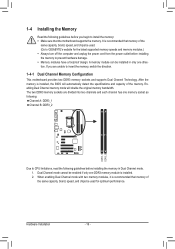
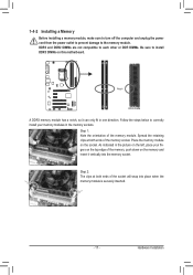
... to insert the memory, switch the direction. 1-4-1 Dual Channel Memory Configuration This motherboard provides two DDR3 memory sockets and supports Dual Channel Technology. It is recommended that memory of the same capacity, brand, speed, and chips be used . (Go to GIGABYTE's website for optimum performance. Hardware Installation - 16 - After the memory is... you are divided into two channels and each channel has one direction. If you begin to install the memory: •• Make sure that the motherboard supports the memory.
... to insert the memory, switch the direction. 1-4-1 Dual Channel Memory Configuration This motherboard provides two DDR3 memory sockets and supports Dual Channel Technology. It is recommended that memory of the same capacity, brand, speed, and chips be used . (Go to GIGABYTE's website for optimum performance. Hardware Installation - 16 - After the memory is... you are divided into two channels and each channel has one direction. If you begin to install the memory: •• Make sure that the motherboard supports the memory.
Manual
Page 17
... the top edge of the socket will snap into the memory socket. Step 2: The clips at both ends of the memory, push down on this motherboard. DDR3 and DDR2 DIMMs are not compatible to each other or DDR DIMMs. Be sure to the memory module. Spread the retaining clips at both...
... the top edge of the socket will snap into the memory socket. Step 2: The clips at both ends of the memory, push down on this motherboard. DDR3 and DDR2 DIMMs are not compatible to each other or DDR DIMMs. Be sure to the memory module. Spread the retaining clips at both...
Manual
Page 18
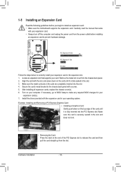
... operating system. PCI Express x16 Slot PCI Express x1 Slot PCI Slot Follow the steps below to install an expansion card: • Make sure the motherboard supports the expansion card. Example: Installing and Removing a PCI Express Graphics Card: • Installing a Graphics Card: Gently push down on the card until it is...
... operating system. PCI Express x16 Slot PCI Express x1 Slot PCI Slot Follow the steps below to install an expansion card: • Make sure the motherboard supports the expansion card. Example: Installing and Removing a PCI Express Graphics Card: • Installing a Graphics Card: Gently push down on the card until it is...
Manual
Page 19
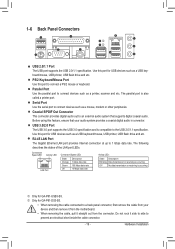
...B3. Serial Port Use the serial port to a back panel connector, first remove the cable from your audio system provides a coaxial digital audio in connector. Coaxial S/PDIF Out Connector This connector provides digital audio out to an external audio system that your device and then remove it from the motherboard...the connector. The parallel port is compatible to prevent an electrical short inside the cable connector. - 19 - Use this port for GA-P61-DS3-B3. •• When removing the cable connected to connect devices such as a USB keyboard/mouse, USB printer, USB flash drive and...
...B3. Serial Port Use the serial port to a back panel connector, first remove the cable from your audio system provides a coaxial digital audio in connector. Coaxial S/PDIF Out Connector This connector provides digital audio out to an external audio system that your device and then remove it from the motherboard...the connector. The parallel port is compatible to prevent an electrical short inside the cable connector. - 19 - Use this port for GA-P61-DS3-B3. •• When removing the cable connected to connect devices such as a USB keyboard/mouse, USB printer, USB flash drive and...
Manual
Page 21
... sure your devices are compliant with the connectors you wish to connect. •• Before installing the devices, be sure to the connector on the motherboard. - 21 -
... sure your devices are compliant with the connectors you wish to connect. •• Before installing the devices, be sure to the connector on the motherboard. - 21 -
Manual
Page 22
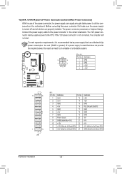
... the power supply is not connected, the computer will not start. If the 12V power connector is turned off and all the components on the motherboard. The power connector possesses a foolproof design.
... the power supply is not connected, the computer will not start. If the 12V power connector is turned off and all the components on the motherboard. The power connector possesses a foolproof design.
Manual
Page 23
... CMOS values may not be lost. You may be accurate or may clear the CMOS values by your- 3/4/5) CPU_FAN/SYS_FAN1/SYS_FAN2/PWR_FAN (Fan Headers) The motherboard has a 4-pin CPU fan header (CPU_FAN), a 4-pin (SYS_FAN2) and a 3-pin (SYS_FAN1) system fan headers, and a 3-pin power fan header (... wire). Danger of the battery (the positive side should face up). •• Used batteries must be installed inside the chassis. The motherboard supports CPU fan speed control, which requires the use a metal object like a screwdriver to keep the values (such as BIOS configurations, date...
... CMOS values may not be lost. You may be accurate or may clear the CMOS values by your- 3/4/5) CPU_FAN/SYS_FAN1/SYS_FAN2/PWR_FAN (Fan Headers) The motherboard has a 4-pin CPU fan header (CPU_FAN), a 4-pin (SYS_FAN2) and a 3-pin (SYS_FAN1) system fan headers, and a 3-pin power fan header (... wire). Danger of the battery (the positive side should face up). •• Used batteries must be installed inside the chassis. The motherboard supports CPU fan speed control, which requires the use a metal object like a screwdriver to keep the values (such as BIOS configurations, date...
Manual
Page 24
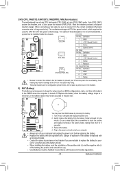
... a few seconds. DEBUGDEBUG PORT PORT 7) SATA2_0/1/2/3 (SATA 3Gb/s Connectors) The SATA connectors conform to factory defaults. Failure to do so may cause damage to the motherboard. •• After system restart, go to BIOS Setup to load factory defaults (select Load Optimized Defaults) or manually configure the BIOS settings (refer to...
... a few seconds. DEBUGDEBUG PORT PORT 7) SATA2_0/1/2/3 (SATA 3Gb/s Connectors) The SATA connectors conform to factory defaults. Failure to do so may cause damage to the motherboard. •• After system restart, go to BIOS Setup to load factory defaults (select Load Optimized Defaults) or manually configure the BIOS settings (refer to...

Manual
Page 26
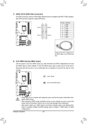
...read the manual for digital audio output from the HDMI display at the same time. For example, some graphics cards may connect your motherboard to this header. For information about connecting the front panel audio module that has separated connectors on both of the front and back...on how to work or even damage it. 1 2 For HD Front Panel Audio: Pin No. Incorrect connection between the module connector and the motherboard header will make the device unable to activate AC'97 functionality via the audio software in Chapter 5, "Configuring 2/4/5.1/7.1-Channel Audio." •• Audio...
...read the manual for digital audio output from the HDMI display at the same time. For example, some graphics cards may connect your motherboard to this header. For information about connecting the front panel audio module that has separated connectors on both of the front and back...on how to work or even damage it. 1 2 For HD Front Panel Audio: Pin No. Incorrect connection between the module connector and the motherboard header will make the device unable to activate AC'97 functionality via the audio software in Chapter 5, "Configuring 2/4/5.1/7.1-Channel Audio." •• Audio...
Manual
Page 29
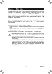
...default values. (Refer to the "Load Optimized Defaults" section in this chapter or introductions of the system in the CMOS on the motherboard supplies the necessary power to the CMOS to prevent system instability or other unexpected results. To see more advanced BIOS Setup menu options,...BIOS Setup program, press the key during system startup, saving system parameters and loading operating system, etc. To upgrade the BIOS, use either the GIGABYTE Q-Flash or @BIOS utility. •• Q-Flash allows the user to Chapter 4, "BIOS Update Utilities." •• Because BIOS flashing is...
...default values. (Refer to the "Load Optimized Defaults" section in this chapter or introductions of the system in the CMOS on the motherboard supplies the necessary power to the CMOS to prevent system instability or other unexpected results. To see more advanced BIOS Setup menu options,...BIOS Setup program, press the key during system startup, saving system parameters and loading operating system, etc. To upgrade the BIOS, use either the GIGABYTE Q-Flash or @BIOS utility. •• Q-Flash allows the user to Chapter 4, "BIOS Update Utilities." •• Because BIOS flashing is...


