Manual
Page 4
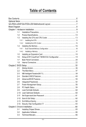
Table of Contents Box Contents...6 Optional Items...6 GA-P55A-UD4P/GA-P55A-UD4 Motherboard Layout 7 Block Diagram...8 Chapter 1 Hardware Installation 9 1-1 Installation Precautions 9 1-2 Product Specifications 10 1-3 Installing the CPU and CPU Cooler 13 1-3-1 Installing the CPU 13 1-3-2 Installing the ... Optimized Defaults 60 2-11 Set Supervisor/User Password 61 2-12 Save & Exit Setup 62 2-13 Exit Without Saving 62 2-14 Security Chip Configuration j 63 Chapter 3 Drivers Installation 65 3-1 Installing Chipset Drivers 65 3-2 Application Software 66 3-3 Technical Manuals 66 - 4 -
Table of Contents Box Contents...6 Optional Items...6 GA-P55A-UD4P/GA-P55A-UD4 Motherboard Layout 7 Block Diagram...8 Chapter 1 Hardware Installation 9 1-1 Installation Precautions 9 1-2 Product Specifications 10 1-3 Installing the CPU and CPU Cooler 13 1-3-1 Installing the CPU 13 1-3-2 Installing the ... Optimized Defaults 60 2-11 Set Supervisor/User Password 61 2-12 Save & Exit Setup 62 2-13 Exit Without Saving 62 2-14 Security Chip Configuration j 63 Chapter 3 Drivers Installation 65 3-1 Installing Chipset Drivers 65 3-2 Application Software 66 3-3 Technical Manuals 66 - 4 -

Manual
Page 5
... 101 5-1-4 Making a SATA RAID/AHCI Driver Diskette 106 5-1-5 Installing the SATA RAID/AHCI Driver and Operating System 108 5-2 Configuring Audio ...Input and Output 121 5-2-1 Configuring 2/4/5.1/7.1-Channel Audio 121 5-2-2 Configuring S/PDIF In/Out 123 5-2-3 Enabling the Dolby Home Theater Function 125 5-2-4 Configuring Microphone Recording 126 5-2-5 Using the Sound Recorder 128 5-3 Troubleshooting 129 5-3-1 Frequently Asked Questions 129 5-3-2 Troubleshooting Procedure 130 5-4 Regulatory Statements 132 j Only for GA-P55A-UD4P...
... 101 5-1-4 Making a SATA RAID/AHCI Driver Diskette 106 5-1-5 Installing the SATA RAID/AHCI Driver and Operating System 108 5-2 Configuring Audio ...Input and Output 121 5-2-1 Configuring 2/4/5.1/7.1-Channel Audio 121 5-2-2 Configuring S/PDIF In/Out 123 5-2-3 Enabling the Dolby Home Theater Function 125 5-2-4 Configuring Microphone Recording 126 5-2-5 Using the Sound Recorder 128 5-3 Troubleshooting 129 5-3-1 Frequently Asked Questions 129 5-3-2 Troubleshooting Procedure 130 5-4 Regulatory Statements 132 j Only for GA-P55A-UD4P...
Manual
Page 6
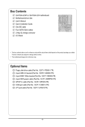
...-0*R) S/PDIF In cable (Part No. 12CR1-1SPDIN-0*R) COM port cable (Part No. 12CF1-1CM001-3*R) LPT port cable (Part No. 12CF1-1LP001-0*R) - 6 - Box Contents GA-P55A-UD4P or GA-P55A-UD4 motherboard Motherboard driver disk User's Manual Quick Installation Guide One IDE cable Four SATA 3Gb/s cables 2-Way SLI bridge connector I/O Shield • The box contents above are...
...-0*R) S/PDIF In cable (Part No. 12CR1-1SPDIN-0*R) COM port cable (Part No. 12CF1-1CM001-3*R) LPT port cable (Part No. 12CF1-1LP001-0*R) - 6 - Box Contents GA-P55A-UD4P or GA-P55A-UD4 motherboard Motherboard driver disk User's Manual Quick Installation Guide One IDE cable Four SATA 3Gb/s cables 2-Way SLI bridge connector I/O Shield • The box contents above are...
Manual
Page 36
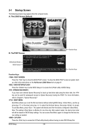
The LOGO Screen (Default) B. To show the BIOS POST screen. In Boot Menu, use the up hard drive data using the driver disk, the key can access Boot Menu again to change the first boot device setting as needed. : Q-FLASH Press the key to Xpress Recovery2 ... Screen Award Modular BIOS v6.00PG, An Energy Star Ally Copyright (C) 1984-2009, Award Software, Inc. To exit Boot Menu, press . Motherboard Model BIOS Version P55A-UD4P D20 . . . . : BIOS Setup : XpressRecovery2 : Boot Menu : Qflash 09/23/2009-P55-7A89RG0WC-00 Function Keys Function Keys Function Keys: : POST SCREEN Press the key...
The LOGO Screen (Default) B. To show the BIOS POST screen. In Boot Menu, use the up hard drive data using the driver disk, the key can access Boot Menu again to change the first boot device setting as needed. : Q-FLASH Press the key to Xpress Recovery2 ... Screen Award Modular BIOS v6.00PG, An Energy Star Ally Copyright (C) 1984-2009, Award Software, Inc. To exit Boot Menu, press . Motherboard Model BIOS Version P55A-UD4P D20 . . . . : BIOS Setup : XpressRecovery2 : Boot Menu : Qflash 09/23/2009-P55-7A89RG0WC-00 Function Keys Function Keys Function Keys: : POST SCREEN Press the key...
Manual
Page 53
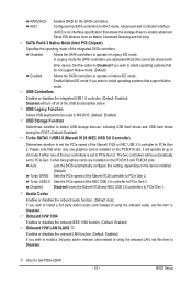
... onboard LAN function. (Default: Enabled) If you wish to PCIe Gen 2. The two controllers will be shared with other device. RAID(XHD) Enables RAID for GA-P55A-UD4P. - 53 - SATA Port0-3 Native Mode (Intel P55 Chipset) Specifies the operating mode of the Marvell 9128 or NEC USB 3.0 controller to install a 3rd party add... of the NEC USB 3.0 controller to enable advanced Serial ATA features such as Native Command Queuing and hot plug. Please note that allows the storage driver to PCIe Gen 2.
... onboard LAN function. (Default: Enabled) If you wish to PCIe Gen 2. The two controllers will be shared with other device. RAID(XHD) Enables RAID for GA-P55A-UD4P. - 53 - SATA Port0-3 Native Mode (Intel P55 Chipset) Specifies the operating mode of the Marvell 9128 or NEC USB 3.0 controller to install a 3rd party add... of the NEC USB 3.0 controller to enable advanced Serial ATA features such as Native Command Queuing and hot plug. Please note that allows the storage driver to PCIe Gen 2.

Manual
Page 55
...IRQ5, 3BC/IRQ7, Disabled. Advanced Host Controller Interface (AHCI) is an interface specification that allows the storage driver to configure RAID for the Marvell 9128 SATA controller. Refer to AHCI mode. Advanced Host Controller Interface (...AHCI) is an interface specification that allows the storage driver to AHCI mode. GSATA Controller (Marvell 9128 Chip, GSATA3_6/7 Connectors) Enables or disables the SATA controller ...RAID Enables RAID for the onboard parallel (LPT) port. j Only for GA-P55A-UD4P. - 55 -
...IRQ5, 3BC/IRQ7, Disabled. Advanced Host Controller Interface (AHCI) is an interface specification that allows the storage driver to configure RAID for the Marvell 9128 SATA controller. Refer to AHCI mode. Advanced Host Controller Interface (...AHCI) is an interface specification that allows the storage driver to AHCI mode. GSATA Controller (Marvell 9128 Chip, GSATA3_6/7 Connectors) Enables or disables the SATA controller ...RAID Enables RAID for the onboard parallel (LPT) port. j Only for GA-P55A-UD4P. - 55 -
Manual
Page 83
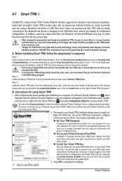
...Install New Utilities menu. Step 3: Install the Smart TPM utility from the motherboard driver disk (select Infineon TPM Driver). Instructions for using your computer, the Infineon Security Platform icon , which your ... plugging in sequence: Step 1: As the computer starts, enter the BIOS Setup program. GIGABYTE is not yet initialized, will store the encrypted TPM User Password in the BIOS main... steps below in the USB flash drive that the Infineon Security Platform is not liable for GA-P55A-UD4P. - 83 - Save changes and then restart your PSD will become inaccessible after the TPM...
...Install New Utilities menu. Step 3: Install the Smart TPM utility from the motherboard driver disk (select Infineon TPM Driver). Instructions for using your computer, the Infineon Security Platform icon , which your ... plugging in sequence: Step 1: As the computer starts, enter the BIOS Setup program. GIGABYTE is not yet initialized, will store the encrypted TPM User Password in the BIOS main... steps below in the USB flash drive that the Infineon Security Platform is not liable for GA-P55A-UD4P. - 83 - Save changes and then restart your PSD will become inaccessible after the TPM...
Manual
Page 86
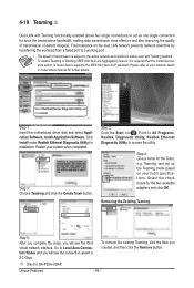
... Utility and click Install. Step 3: Choose Teaming and click the Create Team button. Step 4: Give a name for GA-P55A-UD4P. work switch or router device supports the IEEE 802.3ad LACP standard. Step 1: Insert the motherboard driver disk and select Application Software, Install Application Software. Removing the Existing Teaming: Step 5: After you complete the...
... Utility and click Install. Step 3: Choose Teaming and click the Create Team button. Step 4: Give a name for GA-P55A-UD4P. work switch or router device supports the IEEE 802.3ad LACP standard. Step 1: Insert the motherboard driver disk and select Application Software, Install Application Software. Removing the Existing Teaming: Step 5: After you complete the...


