Manual
Page 4
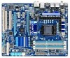
Table of Contents Box Contents...6 Optional Items...6 GA-P55A-UD4P/GA-P55A-UD4 Motherboard Layout 7 Block Diagram...8 Chapter 1 Hardware Installation 9 1-1 Installation Precautions 9 1-2 Product Specifications 10 1-3 Installing the CPU and CPU Cooler 13 1-3-1 Installing the CPU 13 1-3-2 Installing the CPU Cooler 15 1-4 Installing the Memory 16 1-4-1 Dual Channel Memory Configuration 16 1-4-2 Installing a Memory 17 1-5 Installing an Expansion Card 18 1-6 Setup...
Table of Contents Box Contents...6 Optional Items...6 GA-P55A-UD4P/GA-P55A-UD4 Motherboard Layout 7 Block Diagram...8 Chapter 1 Hardware Installation 9 1-1 Installation Precautions 9 1-2 Product Specifications 10 1-3 Installing the CPU and CPU Cooler 13 1-3-1 Installing the CPU 13 1-3-2 Installing the CPU Cooler 15 1-4 Installing the Memory 16 1-4-1 Dual Channel Memory Configuration 16 1-4-2 Installing a Memory 17 1-5 Installing an Expansion Card 18 1-6 Setup...
Manual
Page 8
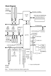
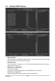
... x1 2 SATA 6Gb/s PCI Bus Marvell 9128 TSB43AB23 IT8213 3 IEEE 1394a LGA1156 CPU CPU CLK+/- (133 MHz) DDR3 2200/1333/1066/800 MHz Dual Channel Memory DMI Interface PCI Express Bus x1 2 SATA 3Gb/s JMB362 Intel® P55 Dual BIOS 6 SATA 3Gb/s 12 USB 2.0/1.1 LPC Bus IT8720 Floppy COM Port CODEC... Speaker Out Center/Subwoofer Speaker Out Side Speaker Out MIC Line Out Line In S/PDIF In S/PDIF Out 2 PCI PCI CLK (33 MHz) j Only for GA-P55A-UD4P. (Note) This feature is optional due to different regional policy. - 8 -
... x1 2 SATA 6Gb/s PCI Bus Marvell 9128 TSB43AB23 IT8213 3 IEEE 1394a LGA1156 CPU CPU CLK+/- (133 MHz) DDR3 2200/1333/1066/800 MHz Dual Channel Memory DMI Interface PCI Express Bus x1 2 SATA 3Gb/s JMB362 Intel® P55 Dual BIOS 6 SATA 3Gb/s 12 USB 2.0/1.1 LPC Bus IT8720 Floppy COM Port CODEC... Speaker Out Center/Subwoofer Speaker Out Side Speaker Out MIC Line Out Line In S/PDIF In S/PDIF Out 2 PCI PCI CLK (33 MHz) j Only for GA-P55A-UD4P. (Note) This feature is optional due to different regional policy. - 8 -
Manual
Page 9
...-temperature environment. • Turning on the computer power during the installation process can lead to damage to system components as well as a motherboard, CPU or memory.
...-temperature environment. • Turning on the computer power during the installation process can lead to damage to system components as well as a motherboard, CPU or memory.
Manual
Page 10
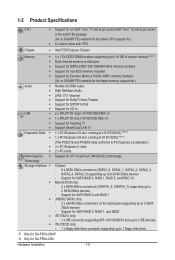
...GB of system memory (Note 1) Dual channel memory architecture Support for DDR3 2200/1333/1066/800 MHz memory modules Support for non-ECC memory modules Support for Extreme Memory Profile (XMP) memory modules (Go to GIGABYTE's website for the latest memory support list.)...up to 2 IDE devices iTE IT8720 chip: - 1 x floppy disk drive connector supporting up to 1 floppy disk drive j Only for GA-P55A-UD4. Support for SATA RAID 0, RAID 1, RAID 5, and RAID 10 Marvell 9128 chip: - 2 x SATA 6Gb/s connectors (GSATA3_6, GSATA3_7)...
...GB of system memory (Note 1) Dual channel memory architecture Support for DDR3 2200/1333/1066/800 MHz memory modules Support for non-ECC memory modules Support for Extreme Memory Profile (XMP) memory modules (Go to GIGABYTE's website for the latest memory support list.)...up to 2 IDE devices iTE IT8720 chip: - 1 x floppy disk drive connector supporting up to 1 floppy disk drive j Only for GA-P55A-UD4. Support for SATA RAID 0, RAID 1, RAID 5, and RAID 10 Marvell 9128 chip: - 2 x SATA 6Gb/s connectors (GSATA3_6, GSATA3_7)...
Manual
Page 12
...® 7/Vista/XP Form Factor w ATX Form Factor; 30.5cm x 24.4cm j Only for GA-P55A-UD4P. (Note 1) Due to Windows Vista/XP 32-bit operating system limitation, when more than 4 GB of physical memory is installed, the actual memory size displayed will be less than 4 GB. (Note 2) For optimum performance, if only one...
...® 7/Vista/XP Form Factor w ATX Form Factor; 30.5cm x 24.4cm j Only for GA-P55A-UD4P. (Note 1) Due to Windows Vista/XP 32-bit operating system limitation, when more than 4 GB of physical memory is installed, the actual memory size displayed will be less than 4 GB. (Note 2) For optimum performance, if only one...
Manual
Page 13
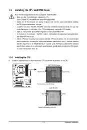
...the CPU. If you wish to set beyond the standard specifications, please do so according to your hardware specifications including the CPU, graphics card, memory, hard drive, etc. 1-3-1 Installing the CPU A. 1-3 Installing the CPU and CPU Cooler Read the following guidelines before installing the CPU to ... the power outlet before you begin to install the CPU: • Make sure that the motherboard supports the CPU. (Go to GIGABYTE's website for the peripherals. The CPU cannot be set the frequency beyond hardware specifications since it does not meet the standard requirements for...
...the CPU. If you wish to set beyond the standard specifications, please do so according to your hardware specifications including the CPU, graphics card, memory, hard drive, etc. 1-3-1 Installing the CPU A. 1-3 Installing the CPU and CPU Cooler Read the following guidelines before installing the CPU to ... the power outlet before you begin to install the CPU: • Make sure that the motherboard supports the CPU. (Go to GIGABYTE's website for the peripherals. The CPU cannot be set the frequency beyond hardware specifications since it does not meet the standard requirements for...
Manual
Page 16
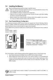
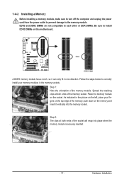
... and DDR3_3 sockets. Dual Channel mode cannot be enabled if only one DDR3 memory module is installed, it is recommended that memory of the memory. A memory module can be sure to GIGABYTE's website for optimum performance. Hardware Installation - 16 - 1-4 Installing the Memory Read the following guidelines before you are divided into two channels and each channel...
... and DDR3_3 sockets. Dual Channel mode cannot be enabled if only one DDR3 memory module is installed, it is recommended that memory of the memory. A memory module can be sure to GIGABYTE's website for optimum performance. Hardware Installation - 16 - 1-4 Installing the Memory Read the following guidelines before you are divided into two channels and each channel...
Manual
Page 17
.... As indicated in the picture on the left, place your memory modules in one direction. Step 2: The clips at both ends of the memory, push down on the memory and insert it can only fit in the memory sockets. 1-4-2 Installing a Memory Before installing a memory module, make sure to turn off the computer and unplug the power... DIMMs on this motherboard. Follow the steps below to correctly install your fingers on the socket. Spread the retaining clips at both ends of the memory module. DDR3 and DDR2 DIMMs are not compatible to each other or DDR DIMMs. Be sure to the...
.... As indicated in the picture on the left, place your memory modules in one direction. Step 2: The clips at both ends of the memory, push down on the memory and insert it can only fit in the memory sockets. 1-4-2 Installing a Memory Before installing a memory module, make sure to turn off the computer and unplug the power... DIMMs on this motherboard. Follow the steps below to correctly install your fingers on the socket. Spread the retaining clips at both ends of the memory module. DDR3 and DDR2 DIMMs are not compatible to each other or DDR DIMMs. Be sure to the...

Manual
Page 38
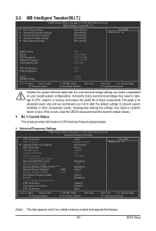
... load, then press to complete. MB Intelligent Tweaker(M.I.T.) Use this menu to configure the clock, frequency and voltages of your CPU, memory, etc. Standard CMOS Features Use this menu to configure the system time and date, hard drive types, floppy disk drive types, and...-Safe defaults are factory settings for the most stable, minimal-performance system operations. Load Optimized Defaults Optimized defaults are factory settings for GA-P55A-UD4P. The Functions of the and keys (For the Main Menu Only) F11: Save CMOS to BIOS This function ...
... load, then press to complete. MB Intelligent Tweaker(M.I.T.) Use this menu to configure the clock, frequency and voltages of your CPU, memory, etc. Standard CMOS Features Use this menu to configure the system time and date, hard drive types, floppy disk drive types, and...-Safe defaults are factory settings for the most stable, minimal-performance system operations. Load Optimized Defaults Optimized defaults are factory settings for GA-P55A-UD4P. The Functions of the and keys (For the Main Menu Only) F11: Save CMOS to BIOS This function ...
Manual
Page 39
...Tweaker(M.I.T.) CMOS Setup Utility-Copyright (C) 1984-2009 Award Software MB Intelligent Tweaker(M.I.T.) } M.I.T Current Status } Advanced Frequency Settings } Advanced Memory Settings } Advanced Voltage Settings } Miscellaneous Settings [Press Enter] [Press Enter] [Press Enter] [Press Enter] [Press Enter] Item ...Help Menu Level BIOS Version BCLK CPU Frequency Memory Frequency Total Memory Size D20 136.73 MHz 2871.41 MHz 1367.27 MHz 2048 MB CPU Temperature PCH Temperature 45oC 40oC Vcore...
...Tweaker(M.I.T.) CMOS Setup Utility-Copyright (C) 1984-2009 Award Software MB Intelligent Tweaker(M.I.T.) } M.I.T Current Status } Advanced Frequency Settings } Advanced Memory Settings } Advanced Voltage Settings } Miscellaneous Settings [Press Enter] [Press Enter] [Press Enter] [Press Enter] [Press Enter] Item ...Help Menu Level BIOS Version BCLK CPU Frequency Memory Frequency Total Memory Size D20 136.73 MHz 2871.41 MHz 1367.27 MHz 2048 MB CPU Temperature PCH Temperature 45oC 40oC Vcore...

Manual
Page 42
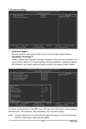
...Mhz) Allows you to manually set the PCIe clock frequency. The adjustable range is designed to automatically adjust CPU computing power to enhance memory performance when enabled. Warning: Before using C.I .A.2) is from 100 MHz to adjust the amplitude of your CPU. PCI Express Clock ... are : 700mV, 800mV, 900mV (default), 1000mV. (Note) This item appears only if you to the BCLK Frequency(Mhz) and System Memory Multiplier settings. Full Thrust Increases CPU frequency by 15% or 17% depending on CPU loading through the use of 5 preset states. Sports Increases...
...Mhz) Allows you to manually set the PCIe clock frequency. The adjustable range is designed to automatically adjust CPU computing power to enhance memory performance when enabled. Warning: Before using C.I .A.2) is from 100 MHz to adjust the amplitude of your CPU. PCI Express Clock ... are : 700mV, 800mV, 900mV (default), 1000mV. (Note) This item appears only if you to the BCLK Frequency(Mhz) and System Memory Multiplier settings. Full Thrust Increases CPU frequency by 15% or 17% depending on CPU loading through the use of 5 preset states. Sports Increases...
Manual
Page 43
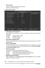
.... Performance Enhance Allows the system to be configurable. Options are : 0ps~750ps. (Default: 0ps) Advanced Memory Settings CMOS Setup Utility-Copyright (C) 1984-2009 Award Software Advanced Memory Settings Extreme Memory Profile (X.M.P.) (Note) System Memory Multiplier (SPD) Memory Frequency (Mhz) 1333 Performance Enhance DRAM Timing Selectable (SPD) Profile DDR Voltage Profile QPI Voltage x Channel Interleaving...
.... Performance Enhance Allows the system to be configurable. Options are : 0ps~750ps. (Default: 0ps) Advanced Memory Settings CMOS Setup Utility-Copyright (C) 1984-2009 Award Software Advanced Memory Settings Extreme Memory Profile (X.M.P.) (Note) System Memory Multiplier (SPD) Memory Frequency (Mhz) 1333 Performance Enhance DRAM Timing Selectable (SPD) Profile DDR Voltage Profile QPI Voltage x Channel Interleaving...

Manual
Page 44
... - tRAS Options are: Auto (default), 1~31. >>>>> Channel A/B Advanced Timing Control tRC Options are: Auto (default), 1~63. Profile DDR Voltage When using a non-XMP memory module or Extreme Memory Profile (X.M.P.) is set to Disabled, this item will display as 1.5V. Profile QPI Voltage The value displayed here is set to Profile1 or Profile2...
... - tRAS Options are: Auto (default), 1~31. >>>>> Channel A/B Advanced Timing Control tRC Options are: Auto (default), 1~63. Profile DDR Voltage When using a non-XMP memory module or Extreme Memory Profile (X.M.P.) is set to Disabled, this item will display as 1.5V. Profile QPI Voltage The value displayed here is set to Profile1 or Profile2...
Manual
Page 47
... Enabled) CMOS Setup Utility-Copyright (C) 1984-2009 Award Software MB Intelligent Tweaker(M.I.T.) } M.I.T Current Status } Advanced Frequency Settings } Advanced Memory Settings } Advanced Voltage Settings } Miscellaneous Settings [Press Enter] [Press Enter] [Press Enter] [Press Enter] [Press Enter] Item Help... Menu Level BIOS Version BCLK CPU Frequency Memory Frequency Total Memory Size D20 136.73 MHz 2871.41 MHz 1367.27 MHz 2048 MB CPU Temperature PCH Temperature 45oC 40oC Vcore...
... Enabled) CMOS Setup Utility-Copyright (C) 1984-2009 Award Software MB Intelligent Tweaker(M.I.T.) } M.I.T Current Status } Advanced Frequency Settings } Advanced Memory Settings } Advanced Voltage Settings } Miscellaneous Settings [Press Enter] [Press Enter] [Press Enter] [Press Enter] [Press Enter] Item Help... Menu Level BIOS Version BCLK CPU Frequency Memory Frequency Total Memory Size D20 136.73 MHz 2871.41 MHz 1367.27 MHz 2048 MB CPU Temperature PCH Temperature 45oC 40oC Vcore...
Manual
Page 48
...-Safe Defaults ESC: Exit F1: General Help F7: Optimized Defaults CMOS Setup Utility-Copyright (C) 1984-2009 Award Software Standard CMOS Features Halt On Base Memory Extended Memory Total Memory [All, But Keyboard] 640K 1022M 1024M Item Help Menu Level Move Enter: Select F5: Previous Values +/-/PU/PD: Value F10: Save F6: Fail...
...-Safe Defaults ESC: Exit F1: General Help F7: Optimized Defaults CMOS Setup Utility-Copyright (C) 1984-2009 Award Software Standard CMOS Features Halt On Base Memory Extended Memory Total Memory [All, But Keyboard] 640K 1022M 1024M Item Help Menu Level Move Enter: Select F5: Previous Values +/-/PU/PD: Value F10: Save F6: Fail...
Manual
Page 49
...when the hard drive access mode is set to CHS. Capacity Approximate capacity of cylinders. Drive A Allows you to select the type of extended memory. Extended Memory The amount of floppy disk drive installed in your system. IDE Channel 2, 3 Master, 4, 6 Master/Slave, 7 Master, 9 Master/...detects a non-fatal error the system boot will stop for an error during the POST. Total Memory The total amount of memory installed on the hard drive. Base Memory Also called conventional memory. Memory These fields are read-only and are : Auto (default), CHS, LBA, Large. All, ...
...when the hard drive access mode is set to CHS. Capacity Approximate capacity of cylinders. Drive A Allows you to select the type of extended memory. Extended Memory The amount of floppy disk drive installed in your system. IDE Channel 2, 3 Master, 4, 6 Master/Slave, 7 Master, 9 Master/...detects a non-fatal error the system boot will stop for an error during the POST. Total Memory The total amount of memory installed on the hard drive. Base Memory Also called conventional memory. Memory These fields are read-only and are : Auto (default), CHS, LBA, Large. All, ...
Manual
Page 50
... Disk Boot Priority Quick Boot First Boot Device Second Boot Device Third Boot Device Password Check HDD S.M.A.R.T. Capability Limit CPUID Max. to 3 (Note) No-Execute Memory Protect (Note) Delay For HDD (Secs) Full Screen LOGO Show Backup BIOS Image to deliver greater efficiency for entering the BIOS Setup program. Use the...
... Disk Boot Priority Quick Boot First Boot Device Second Boot Device Third Boot Device Password Check HDD S.M.A.R.T. Capability Limit CPUID Max. to 3 (Note) No-Execute Memory Protect (Note) Delay For HDD (Secs) Full Screen LOGO Show Backup BIOS Image to deliver greater efficiency for entering the BIOS Setup program. Use the...
Manual
Page 51
...the system BIOS is corrupted, it will be recovered from 0 to 15 seconds. (Default: 0) Full Screen LOGO Show Allows you to display the GIGABYTE Logo at system startup. For more information about Intel CPUs' unique features, please visit Intel's website. - 51 - set a delay time for...the first display. (Default) PEG Sets the PCI Express graphics card on the PCIEX8 slot as Windows NT4.0. (Default: Disabled) No-Execute Memory Protect (Note) Enables or disables Intel Execute Disable Bit function. Disabled displays normal POST message. (Default: Enabled) Backup BIOS Image to ...
...the system BIOS is corrupted, it will be recovered from 0 to 15 seconds. (Default: 0) Full Screen LOGO Show Allows you to display the GIGABYTE Logo at system startup. For more information about Intel CPUs' unique features, please visit Intel's website. - 51 - set a delay time for...the first display. (Default) PEG Sets the PCI Express graphics card on the PCIEX8 slot as Windows NT4.0. (Default: Disabled) No-Execute Memory Protect (Note) Enables or disables Intel Execute Disable Bit function. Disabled displays normal POST message. (Default: Enabled) Backup BIOS Image to ...
Manual
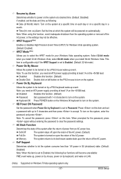
Page 57
... automatically. AC Back Function Determines the state of the system after the return of power from the operating system or removal of the AC power. Memory The system returns to its last known awake state upon the return of the AC power, or the settings may not be powered on this...
... automatically. AC Back Function Determines the state of the system after the return of power from the operating system or removal of the AC power. Memory The system returns to its last known awake state upon the return of the AC power, or the settings may not be powered on this...

Manual
Page 69
... Xpress Recovery2 are attached to the first IDE and the first SATA connectors, the hard drive on your system data and perform restoration of system memory • VESA compatible graphics card • Windows XP with Xpress Recovery cannot be restored using Xpress Recovery2. • USB hard drives are not supported. •...
... Xpress Recovery2 are attached to the first IDE and the first SATA connectors, the hard drive on your system data and perform restoration of system memory • VESA compatible graphics card • Windows XP with Xpress Recovery cannot be restored using Xpress Recovery2. • USB hard drives are not supported. •...


