Manual
Page 4
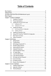
Table of Contents Box Contents...6 Optional Items...6 GA-P55A-UD4P/GA-P55A-UD4 Motherboard Layout 7 Block Diagram...8 Chapter 1 Hardware Installation 9 1-1 Installation Precautions 9 1-2 Product Specifications 10 1-3 Installing the CPU and CPU Cooler 13 1-3-1 Installing the CPU 13 1-3-2 Installing the CPU Cooler 15 1-4 Installing the Memory 16 1-4-1 Dual Channel Memory Configuration 16 1-4-2 Installing a Memory 17 1-5 Installing an Expansion Card 18 1-6 Setup of...
Table of Contents Box Contents...6 Optional Items...6 GA-P55A-UD4P/GA-P55A-UD4 Motherboard Layout 7 Block Diagram...8 Chapter 1 Hardware Installation 9 1-1 Installation Precautions 9 1-2 Product Specifications 10 1-3 Installing the CPU and CPU Cooler 13 1-3-1 Installing the CPU 13 1-3-2 Installing the CPU Cooler 15 1-4 Installing the Memory 16 1-4-1 Dual Channel Memory Configuration 16 1-4-2 Installing a Memory 17 1-5 Installing an Expansion Card 18 1-6 Setup of...
Manual
Page 8
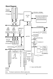
... x1 2 SATA 6Gb/s PCI Bus Marvell 9128 TSB43AB23 IT8213 3 IEEE 1394a LGA1156 CPU CPU CLK+/- (133 MHz) DDR3 2200/1333/1066/800 MHz Dual Channel Memory DMI Interface PCI Express Bus x1 2 SATA 3Gb/s JMB362 Intel® P55 Dual BIOS 6 SATA 3Gb/s 12 USB 2.0/1.1 LPC Bus IT8720 Floppy COM Port CODEC... Speaker Out Center/Subwoofer Speaker Out Side Speaker Out MIC Line Out Line In S/PDIF In S/PDIF Out 2 PCI PCI CLK (33 MHz) j Only for GA-P55A-UD4P. (Note) This feature is optional due to different regional policy. - 8 -
... x1 2 SATA 6Gb/s PCI Bus Marvell 9128 TSB43AB23 IT8213 3 IEEE 1394a LGA1156 CPU CPU CLK+/- (133 MHz) DDR3 2200/1333/1066/800 MHz Dual Channel Memory DMI Interface PCI Express Bus x1 2 SATA 3Gb/s JMB362 Intel® P55 Dual BIOS 6 SATA 3Gb/s 12 USB 2.0/1.1 LPC Bus IT8720 Floppy COM Port CODEC... Speaker Out Center/Subwoofer Speaker Out Side Speaker Out MIC Line Out Line In S/PDIF In S/PDIF Out 2 PCI PCI CLK (33 MHz) j Only for GA-P55A-UD4P. (Note) This feature is optional due to different regional policy. - 8 -
Manual
Page 10
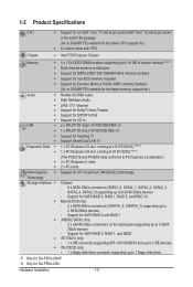
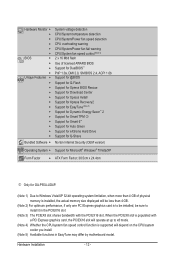
...memory (Note 1) Dual channel memory architecture Support for DDR3 2200/1333/1066/800 MHz memory modules Support for non-ECC memory modules Support for Extreme Memory Profile (XMP) memory modules (Go to GIGABYTE's website for the latest memory...SATA 3Gb/s connectors (SATA2_0, SATA2_1, SATA2_2, SATA2_3, SATA2_4, SATA2_5) supporting up to 1 floppy disk drive j Only for GA-P55A-UD4P. Support for SATA RAID 0, RAID 1, RAID 5, and RAID 10 Marvell 9128 chip: - 2 x SATA ...to 2 SATA 3Gb/s devices - Support for GA-P55A-UD4.
...memory (Note 1) Dual channel memory architecture Support for DDR3 2200/1333/1066/800 MHz memory modules Support for non-ECC memory modules Support for Extreme Memory Profile (XMP) memory modules (Go to GIGABYTE's website for the latest memory...SATA 3Gb/s connectors (SATA2_0, SATA2_1, SATA2_2, SATA2_3, SATA2_4, SATA2_5) supporting up to 1 floppy disk drive j Only for GA-P55A-UD4P. Support for SATA RAID 0, RAID 1, RAID 5, and RAID 10 Marvell 9128 chip: - 2 x SATA ...to 2 SATA 3Gb/s devices - Support for GA-P55A-UD4.
Manual
Page 12
...® 7/Vista/XP Form Factor w ATX Form Factor; 30.5cm x 24.4cm j Only for GA-P55A-UD4P. (Note 1) Due to Windows Vista/XP 32-bit operating system limitation, when more than 4 GB of physical memory is installed, the actual memory size displayed will be less than 4 GB. (Note 2) For optimum performance, if only one PCI...
...® 7/Vista/XP Form Factor w ATX Form Factor; 30.5cm x 24.4cm j Only for GA-P55A-UD4P. (Note 1) Due to Windows Vista/XP 32-bit operating system limitation, when more than 4 GB of physical memory is installed, the actual memory size displayed will be less than 4 GB. (Note 2) For optimum performance, if only one PCI...

Manual
Page 38
...(to erase the default profile name, use the SPACE key) and then press to complete. F12: Load CMOS from BIOS If your CPU, memory, etc. Standard CMOS Features Use this menu to configure the system time and date, hard drive types, floppy disk drive types, and the ...Fail-Safe defaults are factory settings for the most stable, minimal-performance system operations. Load Optimized Defaults Optimized defaults are factory settings for GA-P55A-UD4P. A user password only allows you to make changes. Save & Exit Setup Save all the changes made in effect.
...(to erase the default profile name, use the SPACE key) and then press to complete. F12: Load CMOS from BIOS If your CPU, memory, etc. Standard CMOS Features Use this menu to configure the system time and date, hard drive types, floppy disk drive types, and the ...Fail-Safe defaults are factory settings for the most stable, minimal-performance system operations. Load Optimized Defaults Optimized defaults are factory settings for GA-P55A-UD4P. A user password only allows you to make changes. Save & Exit Setup Save all the changes made in effect.


