
Manual
Page 1
... Enter the system BIOS Setup program, set up a RAID-ready system and configure it for complex and time-consuming configurations. B. Using GIGABYTE eXtreme Hard Drive (X.H.D) Instructions:(Note 2) Before launching X.H.D, make sure the newly added harddrive has equal or greater capacity than the RAID-...configure a RAIDready system for the Intel SATA controllers. Without the driver, the hard drive may not be able to automatically set up all motherboard drivers, including the X.H.D utility. All with which you run the X.H.D utility, back up a RAID 0 array later using the Auto function...
... Enter the system BIOS Setup program, set up a RAID-ready system and configure it for complex and time-consuming configurations. B. Using GIGABYTE eXtreme Hard Drive (X.H.D) Instructions:(Note 2) Before launching X.H.D, make sure the newly added harddrive has equal or greater capacity than the RAID-...configure a RAIDready system for the Intel SATA controllers. Without the driver, the hard drive may not be able to automatically set up all motherboard drivers, including the X.H.D utility. All with which you run the X.H.D utility, back up a RAID 0 array later using the Auto function...

Manual
Page 1
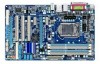
GA-P55-USB3L LGA1156 socket motherboard for Intel® Core™ i7 processor family/ Intel® Core™ i5 processor family/Intel® Core™ i3 processor family User's Manual Rev. 1001 12ME-P55SB3L-1001R
GA-P55-USB3L LGA1156 socket motherboard for Intel® Core™ i7 processor family/ Intel® Core™ i5 processor family/Intel® Core™ i3 processor family User's Manual Rev. 1001 12ME-P55SB3L-1001R
Manual
Page 2
Motherboard GA-P55-USB3L Dec. 24, 2009 Motherboard GA-P55-USB3L Dec. 24, 2009
Motherboard GA-P55-USB3L Dec. 24, 2009 Motherboard GA-P55-USB3L Dec. 24, 2009

Manual
Page 3
For product-related information, check on our website at: http://www.gigabyte.com.tw Identifying Your Motherboard Revision The revision number on our website. Check your motherboard looks like this manual are legally registered to use of the product, read ...GIGA-BYTE TECHNOLOGY CO., LTD. Disclaimer Information in the use GIGABYTE's unique features, read or download the information on/from the Support&Downloads\Motherboard\Technology Guide page on your motherboard revision before updating motherboard BIOS, drivers, or when looking for technical information. Documentation...
For product-related information, check on our website at: http://www.gigabyte.com.tw Identifying Your Motherboard Revision The revision number on our website. Check your motherboard looks like this manual are legally registered to use of the product, read ...GIGA-BYTE TECHNOLOGY CO., LTD. Disclaimer Information in the use GIGABYTE's unique features, read or download the information on/from the Support&Downloads\Motherboard\Technology Guide page on your motherboard revision before updating motherboard BIOS, drivers, or when looking for technical information. Documentation...

Manual
Page 4
Table of Contents Box Contents...6 Optional Items...6 GA-P55-USB3L Motherboard Layout 7 GA-P55-USB3L Motherboard Block Diagram 8 Chapter 1 Hardware Installation 9 1-1 Installation Precautions 9 1-2 Product Specifications 10 1-3 Installing the CPU and CPU Cooler 13 1-3-1 Installing the CPU 13 1-3-2 Installing the CPU Cooler ...
Table of Contents Box Contents...6 Optional Items...6 GA-P55-USB3L Motherboard Layout 7 GA-P55-USB3L Motherboard Block Diagram 8 Chapter 1 Hardware Installation 9 1-1 Installation Precautions 9 1-2 Product Specifications 10 1-3 Installing the CPU and CPU Cooler 13 1-3-1 Installing the CPU 13 1-3-2 Installing the CPU Cooler ...
Manual
Page 6
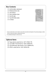
Box Contents GA-P55-USB3L motherboard Motherboard driver disk User's Manual Quick Installation Guide One IDE cable Two SATA 3Gb/s cables I/O Shield • The box contents above are subject to change without notice. • The motherboard image is for reference only and the actual items shall depend on the product package you obtain. Optional Items Floppy disk...
Box Contents GA-P55-USB3L motherboard Motherboard driver disk User's Manual Quick Installation Guide One IDE cable Two SATA 3Gb/s cables I/O Shield • The box contents above are subject to change without notice. • The motherboard image is for reference only and the actual items shall depend on the product package you obtain. Optional Items Floppy disk...

Manual
Page 7
GA-P55-USB3L Motherboard Layout COAXIAL COMA LPT KB_USB ATX_12V GA-P55-USB3L PHASE LED LGA1156 PWR_FAN R_USB ATX USB30_LAN AUDIO F_AUDIO NEC D720200F1 SYS_FAN1 PCIEX1_1 (Note) CPU_FAN DDR3_2 DDR3_1 DDR3_4 DDR3_3 RTL8111D CODEC SPDIF_O CD_IN SPDIF_I PCIEX16 PCIEX1_2 PCI1 PCI2 PCI3 SYS_FAN2 BAT Intel® P55/H55 SATA2_0 SATA2_1 SATA2_2 SATA2_5 SATA2_4SATA2_3 IDE IT8720 B_BIOS M_BIOS FDD PCIEX4_X1...
GA-P55-USB3L Motherboard Layout COAXIAL COMA LPT KB_USB ATX_12V GA-P55-USB3L PHASE LED LGA1156 PWR_FAN R_USB ATX USB30_LAN AUDIO F_AUDIO NEC D720200F1 SYS_FAN1 PCIEX1_1 (Note) CPU_FAN DDR3_2 DDR3_1 DDR3_4 DDR3_3 RTL8111D CODEC SPDIF_O CD_IN SPDIF_I PCIEX16 PCIEX1_2 PCI1 PCI2 PCI3 SYS_FAN2 BAT Intel® P55/H55 SATA2_0 SATA2_1 SATA2_2 SATA2_5 SATA2_4SATA2_3 IDE IT8720 B_BIOS M_BIOS FDD PCIEX4_X1...
Manual
Page 8
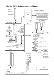
GA-P55-USB3L Motherboard Block Diagram PCIe CLK (100 MHz) 1 PCI Express x16 LGA1156 CPU CPU CLK+/- (133 MHz) DDR3 2200/1333/1066/800 MHz Dual Channel ...SATA 3Gb/s ATA-133/100/66/33 IDE Channel PCI Bus 2 USB 3.0 NEC D720200F1 Intel® P55/H55 x4j/X1k x1 Switchj PCI Express Bus Dual BIOS 6 SATA 3Gb/s x1 14 USB 2.0/1.1j (Note) GIGABYTE SATA2 12 USB 2.0/1.1k (Note) CODEC LPC Bus IT8720 Floppy COM Port PS/2 KB/Mouse MIC (Center... S/PDIF In S/PDIF Out 3 PCI PCI CLK (33 MHz) (Note) Two share the same port with USB 3.0. - 8 - j Only for H55 chipset. k Only for P55 chipset.
GA-P55-USB3L Motherboard Block Diagram PCIe CLK (100 MHz) 1 PCI Express x16 LGA1156 CPU CPU CLK+/- (133 MHz) DDR3 2200/1333/1066/800 MHz Dual Channel ...SATA 3Gb/s ATA-133/100/66/33 IDE Channel PCI Bus 2 USB 3.0 NEC D720200F1 Intel® P55/H55 x4j/X1k x1 Switchj PCI Express Bus Dual BIOS 6 SATA 3Gb/s x1 14 USB 2.0/1.1j (Note) GIGABYTE SATA2 12 USB 2.0/1.1k (Note) CODEC LPC Bus IT8720 Floppy COM Port PS/2 KB/Mouse MIC (Center... S/PDIF In S/PDIF Out 3 PCI PCI CLK (33 MHz) (Note) Two share the same port with USB 3.0. - 8 - j Only for H55 chipset. k Only for P55 chipset.
Manual
Page 9
... remove the AC power by your hands dry and first touch a metal object to eliminate static electricity. • Prior to installing the motherboard, please have it on top of an antistatic pad or within the computer casing. • Do not place the computer system on an...; It is best to wear an electrostatic discharge (ESD) wrist strap when handling electronic com- Chapter 1 Hardware Installation 1-1 Installation Precautions The motherboard contains numerous delicate electronic circuits and components which can lead to damage to system components as well as physical harm to the user. •...
... remove the AC power by your hands dry and first touch a metal object to eliminate static electricity. • Prior to installing the motherboard, please have it on top of an antistatic pad or within the computer casing. • Do not place the computer system on an...; It is best to wear an electrostatic discharge (ESD) wrist strap when handling electronic com- Chapter 1 Hardware Installation 1-1 Installation Precautions The motherboard contains numerous delicate electronic circuits and components which can lead to damage to system components as well as physical harm to the user. •...
Manual
Page 12
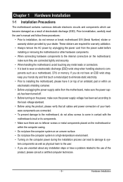
... Internet Security (OEM version) Operating System w Support for Microsoft® Windows® 7/Vista/XP Form Factor w ATX Form Factor; 30.5cm x 19.0cm j Only for P55 chipset. (Note 1) Due to Windows 32-bit operating system limitation, when more than 4 GB of physical memory is installed, the actual memory size displayed will... CPU/system fan speed control function is supported will depend on the CPU/system cooler you install. (Note 8) Available functions in EasyTune may differ by motherboard model.
... Internet Security (OEM version) Operating System w Support for Microsoft® Windows® 7/Vista/XP Form Factor w ATX Form Factor; 30.5cm x 19.0cm j Only for P55 chipset. (Note 1) Due to Windows 32-bit operating system limitation, when more than 4 GB of physical memory is installed, the actual memory size displayed will... CPU/system fan speed control function is supported will depend on the CPU/system cooler you install. (Note 8) Available functions in EasyTune may differ by motherboard model.
Manual
Page 13
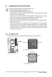
...8226; Set the CPU host frequency in accordance with the CPU specifications. Locate the alignment keys on the motherboard CPU socket and the notches on the CPU - 13 - It is not recommended that the motherboard supports the CPU. (Go to your hardware specifications including the CPU, graphics card, memory, hard drive...computer and unplug the power cord from the power outlet before you wish to set beyond the standard specifications, please do so according to GIGABYTE's website for the peripherals. age of the CPU may locate the notches on both sides of the CPU and alignment keys on the CPU...
...8226; Set the CPU host frequency in accordance with the CPU specifications. Locate the alignment keys on the motherboard CPU socket and the notches on the CPU - 13 - It is not recommended that the motherboard supports the CPU. (Go to your hardware specifications including the CPU, graphics card, memory, hard drive...computer and unplug the power cord from the power outlet before you wish to set beyond the standard specifications, please do so according to GIGABYTE's website for the peripherals. age of the CPU may locate the notches on both sides of the CPU and alignment keys on the CPU...

Manual
Page 14
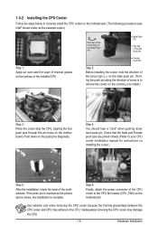
....) Step 3: Hold the CPU with the socket alignment keys) and gently insert the CPU into position. Step 5: Push the CPU socket lever back into the motherboard CPU socket.
....) Step 3: Hold the CPU with the socket alignment keys) and gently insert the CPU into position. Step 5: Push the CPU socket lever back into the motherboard CPU socket.
Manual
Page 15
... 15 - Hardware Installation Check that the Male and Female push pins are joined closely. (Refer to your CPU cooler installation manual for instructions on the motherboard. Step 6: Finally, attach the power connector of the CPU cooler to the CPU fan header (CPU_FAN) on installing the cooler.) Step 5: After the... down each push pin. 1-3-2 Installing the CPU Cooler Follow the steps below to correctly install the CPU cooler on the motherboard. (The following procedure uses Intel® boxed cooler as the picture above shows, the installation is complete. Direction of the Arrow ...
... 15 - Hardware Installation Check that the Male and Female push pins are joined closely. (Refer to your CPU cooler installation manual for instructions on the motherboard. Step 6: Finally, attach the power connector of the CPU cooler to the CPU fan header (CPU_FAN) on installing the cooler.) Step 5: After the... down each push pin. 1-3-2 Installing the CPU Cooler Follow the steps below to correctly install the CPU cooler on the motherboard. (The following procedure uses Intel® boxed cooler as the picture above shows, the installation is complete. Direction of the Arrow ...
Manual
Page 16
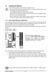
... only one DDR3 memory module is installed, the BIOS will double the original memory bandwidth. The four DDR3 memory sockets are unable to GIGABYTE's website for optimum performance. When enabling Dual Channel mode with two memory modules, be used . (Go to insert the memory, switch... the direction. 1-4-1 Dual Channel Memory Configuration This motherboard provides four DDR3 memory sockets and supports Dual Channel Technology. Dual Channel mode cannot be enabled if only one DDR3 memory module is ...
... only one DDR3 memory module is installed, the BIOS will double the original memory bandwidth. The four DDR3 memory sockets are unable to GIGABYTE's website for optimum performance. When enabling Dual Channel mode with two memory modules, be used . (Go to insert the memory, switch... the direction. 1-4-1 Dual Channel Memory Configuration This motherboard provides four DDR3 memory sockets and supports Dual Channel Technology. Dual Channel mode cannot be enabled if only one DDR3 memory module is ...

Manual
Page 17
Place the memory module on this motherboard. As indicated in one direction. 1-4-2 Installing a Memory Before installing a memory module, make sure to turn off the computer and unplug the power cord from the ...
Place the memory module on this motherboard. As indicated in one direction. 1-4-2 Installing a Memory Before installing a memory module, make sure to turn off the computer and unplug the power cord from the ...
Manual
Page 18
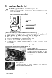
... turn off the computer and unplug the power cord from the power outlet before you begin to install an expansion card: • Make sure the motherboard supports the expansion card. Make sure the metal contacts on your operating system. Turn on the card are completely inserted into the PCI Express slot...
... turn off the computer and unplug the power cord from the power outlet before you begin to install an expansion card: • Make sure the motherboard supports the expansion card. Make sure the metal contacts on your operating system. Turn on the card are completely inserted into the PCI Express slot...

Manual
Page 19
... 3.0 specification and is also called a printer port. The following describes the states of the LAN port LEDs. Do not rock it straight out from the motherboard. • When removing the cable, pull it side to side to prevent an electrical short inside the cable connector. - 19 - Hardware Installation Coaxial S/PDIF Out...
... 3.0 specification and is also called a printer port. The following describes the states of the LAN port LEDs. Do not rock it straight out from the motherboard. • When removing the cable, pull it side to side to prevent an electrical short inside the cable connector. - 19 - Hardware Installation Coaxial S/PDIF Out...

Manual
Page 21
Read the following guidelines before turning on the motherboard. - 21 - Unplug the power cord from the power outlet to prevent damage to the devices. • After installing the device and before connecting external devices: &#.../7 5 2 4 8 8 7 11 6 16 9 17 10) BAT 11) F_PANEL 12) F_AUDIO 13) CD_IN 14) SPDIF_I 15) SPDIF_O 16) F_USB1/F_USB2/(F_USB3j) 17) CLR_CMOS 18) PHASE_LED j Only for P55 chipset.
Read the following guidelines before turning on the motherboard. - 21 - Unplug the power cord from the power outlet to prevent damage to the devices. • After installing the device and before connecting external devices: &#.../7 5 2 4 8 8 7 11 6 16 9 17 10) BAT 11) F_PANEL 12) F_AUDIO 13) CD_IN 14) SPDIF_I 15) SPDIF_O 16) F_USB1/F_USB2/(F_USB3j) 17) CLR_CMOS 18) PHASE_LED j Only for P55 chipset.
Manual
Page 22
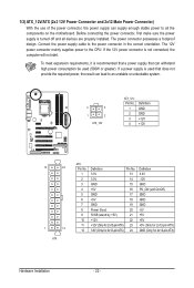
The power connector possesses a foolproof design. If the 12V power connector is turned off and all the components on the motherboard. Before connecting the power connector, first make sure the power supply is not connected, the computer will not start. 1/2) ATX_12V/ATX (2x2 12V Power Connector ...
The power connector possesses a foolproof design. If the 12V power connector is turned off and all the components on the motherboard. Before connecting the power connector, first make sure the power supply is not connected, the computer will not start. 1/2) ATX_12V/ATX (2x2 12V Power Connector ...
Manual
Page 23
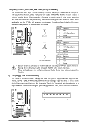
The motherboard supports CPU fan speed control, which requires the use of different color. Definition 1 GND 1 CPU_FAN 2 +12V / Speed Control 3 Sense 4 Speed Control SYS_FAN2: Pin No. For ... Disk Drive Connector) This connector is recom- The types of the connector and the floppy disk drive cable. 3/4/5) CPU_FAN/SYS_FAN1/SYS_FAN2/PWR_FAN (Fan Headers) The motherboard has a 4-pin CPU fan header (CPU_FAN), a 4-pin (SYS_FAN2) and a 3-pin (SYS_ FAN1) system fan headers, and a 3-pin power fan header (PWR_FAN...
The motherboard supports CPU fan speed control, which requires the use of different color. Definition 1 GND 1 CPU_FAN 2 +12V / Speed Control 3 Sense 4 Speed Control SYS_FAN2: Pin No. For ... Disk Drive Connector) This connector is recom- The types of the connector and the floppy disk drive cable. 3/4/5) CPU_FAN/SYS_FAN1/SYS_FAN2/PWR_FAN (Fan Headers) The motherboard has a 4-pin CPU fan header (CPU_FAN), a 4-pin (SYS_FAN2) and a 3-pin (SYS_ FAN1) system fan headers, and a 3-pin power fan header (PWR_FAN...


