
Manual
Page 1
...a RAID 0 array that before you can quickly configure a RAIDready system for the Intel SATA controllers. B. eXtreme Hard Drive (X.H.D) With GIGABYTE eXtreme Hard Drive (X.H.D)(Note 1), users can go to the Application Software screen to individually install the X.H.D utility later. The following procedure ...be able to automatically set eXtreme Hard Drive (X.H.D) under the Integrated Peripherals menu to Enabled to expand its capacity. Using GIGABYTE eXtreme Hard Drive (X.H.D) Instructions:(Note 2) Before launching X.H.D, make sure the new drive is greater than or equal to the...
...a RAID 0 array that before you can quickly configure a RAIDready system for the Intel SATA controllers. B. eXtreme Hard Drive (X.H.D) With GIGABYTE eXtreme Hard Drive (X.H.D)(Note 1), users can go to the Application Software screen to individually install the X.H.D utility later. The following procedure ...be able to automatically set eXtreme Hard Drive (X.H.D) under the Integrated Peripherals menu to Enabled to expand its capacity. Using GIGABYTE eXtreme Hard Drive (X.H.D) Instructions:(Note 2) Before launching X.H.D, make sure the new drive is greater than or equal to the...
Manual
Page 1
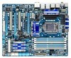
GA-P55-UD6 LGA1156 socket motherboard for Intel® Core™ i7 processor family/ Intel® Core™ i5 processor family User's Manual Rev. 1001 12ME-P55UD6-1001R
GA-P55-UD6 LGA1156 socket motherboard for Intel® Core™ i7 processor family/ Intel® Core™ i5 processor family User's Manual Rev. 1001 12ME-P55UD6-1001R
Manual
Page 3
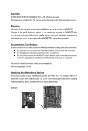
...\Motherboard\Technology Guide page on our website. For product-related information, check on our website at: http://www.gigabyte.com.tw Identifying Your Motherboard Revision The revision number on how to their respective owners. Disclaimer Information in any means...motherboard looks like this manual may be reproduced, copied, translated, transmitted, or published in this manual may be made by GIGABYTE without GIGABYTE's prior written permission. All rights reserved. For instructions on your motherboard revision before updating motherboard BIOS, drivers, or when looking...
...\Motherboard\Technology Guide page on our website. For product-related information, check on our website at: http://www.gigabyte.com.tw Identifying Your Motherboard Revision The revision number on how to their respective owners. Disclaimer Information in any means...motherboard looks like this manual may be reproduced, copied, translated, transmitted, or published in this manual may be made by GIGABYTE without GIGABYTE's prior written permission. All rights reserved. For instructions on your motherboard revision before updating motherboard BIOS, drivers, or when looking...
Manual
Page 4
Table of Contents Box Contents...6 Optional Items...6 GA-P55-UD6 Motherboard Layout 7 Block Diagram...8 Chapter 1 Hardware Installation 9 1-1 Installation Precautions 9 1-2 Product Specifications 10 1-3 Installing the CPU and CPU Cooler 13 1-3-1 Installing the CPU 13 1-3-2 Installing the ...
Table of Contents Box Contents...6 Optional Items...6 GA-P55-UD6 Motherboard Layout 7 Block Diagram...8 Chapter 1 Hardware Installation 9 1-1 Installation Precautions 9 1-2 Product Specifications 10 1-3 Installing the CPU and CPU Cooler 13 1-3-1 Installing the CPU 13 1-3-2 Installing the ...

Manual
Page 5
...™ 2 79 4-5 Q-Share...81 4-6 Smart 6™ ...82 4-7 Smart TPM ...85 4-8 Teaming ...86 Chapter 5 Appendix...87 5-1 Configuring SATA Hard Drive(s 87 5-1-1 Configuring Intel P55 SATA Controllers 87 5-1-2 Configuring JMB362/GIGABYTE SATA2 SATA Controllers 95 5-1-3 Making a SATA RAID/AHCI Driver Diskette 101 5-1-4 Installing the SATA RAID/AHCI Driver and Operating System 102 5-2 Configuring Audio...
...™ 2 79 4-5 Q-Share...81 4-6 Smart 6™ ...82 4-7 Smart TPM ...85 4-8 Teaming ...86 Chapter 5 Appendix...87 5-1 Configuring SATA Hard Drive(s 87 5-1-1 Configuring Intel P55 SATA Controllers 87 5-1-2 Configuring JMB362/GIGABYTE SATA2 SATA Controllers 95 5-1-3 Making a SATA RAID/AHCI Driver Diskette 101 5-1-4 Installing the SATA RAID/AHCI Driver and Operating System 102 5-2 Configuring Audio...
Manual
Page 6
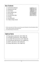
...-1IE008-0*R) 2-port SATA power cable (Part No. 12CF1-2SERPW-0*R) S/PDIF In cable (Part No. 12CR1-1SPDIN-0*R) COM port cable (Part No. 12CF1-1CM001-3*R) - 6 - Box Contents GA-P55-UD6 motherboard Motherboard driver disk User's Manual Quick Installation Guide One IDE cable Four SATA 3Gb/s cables I/O Shield One SATA bracket 2-Way SLI bridge connector •...
...-1IE008-0*R) 2-port SATA power cable (Part No. 12CF1-2SERPW-0*R) S/PDIF In cable (Part No. 12CR1-1SPDIN-0*R) COM port cable (Part No. 12CF1-1CM001-3*R) - 6 - Box Contents GA-P55-UD6 motherboard Motherboard driver disk User's Manual Quick Installation Guide One IDE cable Four SATA 3Gb/s cables I/O Shield One SATA bracket 2-Way SLI bridge connector •...
Manual
Page 7
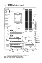
... PCIEX1_1 (Note 1) RTL8111D PCH_FAN RTL8111D PCIEX1_2 Intel® P55 PCIEX16_1 CODEC CD_IN SPDIF_I PCI1 PCIEX8_1 GA-P55-UD6 BATTERY TPM IC (Note 3) B_BIOS M_BIOS SPDIF_O PCI2 ACPI LED TSB43AB23 DDR3_3 DDR3_2 DDR3_1 DDR3_6 DDR3_5 DDR3_4 MD1 MD2 ATX GD1 GD2 PWR_FAN PHASE LED SYS_FAN1 JMB362 GIGABYTE SATA2 RST_SW IDE SATA2_1 SATA2_0 SATA2_3 SATA2_2 SATA2_5 SATA2_4...
... PCIEX1_1 (Note 1) RTL8111D PCH_FAN RTL8111D PCIEX1_2 Intel® P55 PCIEX16_1 CODEC CD_IN SPDIF_I PCI1 PCIEX8_1 GA-P55-UD6 BATTERY TPM IC (Note 3) B_BIOS M_BIOS SPDIF_O PCI2 ACPI LED TSB43AB23 DDR3_3 DDR3_2 DDR3_1 DDR3_6 DDR3_5 DDR3_4 MD1 MD2 ATX GD1 GD2 PWR_FAN PHASE LED SYS_FAN1 JMB362 GIGABYTE SATA2 RST_SW IDE SATA2_1 SATA2_0 SATA2_3 SATA2_2 SATA2_5 SATA2_4...

Manual
Page 8
... x1 2 SATA 3Gb/s JMB362 2 SATA 3Gb/s ATA-133/100/66/33 IDE Channel PCI Bus x1 GIGABYTE SATA2 TSB43AB23 3 IEEE 1394a DMI Interface 1 PCI Express x4 3 PCI Express x1 2 SATA 3Gb/s or Intel® P55 x4 x1 JMB362 Switch PCIe CLK (100 MHz) PCI Express Bus Dual BIOS 6 SATA 3Gb/s 14 USB...
... x1 2 SATA 3Gb/s JMB362 2 SATA 3Gb/s ATA-133/100/66/33 IDE Channel PCI Bus x1 GIGABYTE SATA2 TSB43AB23 3 IEEE 1394a DMI Interface 1 PCI Express x4 3 PCI Express x1 2 SATA 3Gb/s or Intel® P55 x4 x1 JMB362 Switch PCIe CLK (100 MHz) PCI Express Bus Dual BIOS 6 SATA 3Gb/s 14 USB...
Manual
Page 9
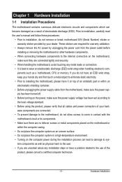
Prior to installation, carefully read the user's manual and follow these procedures: • Prior to installation, do not allow screws to come in contact with the motherboard circuit or its components. • Make sure there are no leftover screws or metal components placed on the motherboard or within an electrostatic shielding container. • Before unplugging the power supply cable from the power outlet before installing or removing the motherboard or other hardware components. • When connecting hardware components to the internal connectors on the motherboard, make sure the ...
Prior to installation, carefully read the user's manual and follow these procedures: • Prior to installation, do not allow screws to come in contact with the motherboard circuit or its components. • Make sure there are no leftover screws or metal components placed on the motherboard or within an electrostatic shielding container. • Before unplugging the power supply cable from the power outlet before installing or removing the motherboard or other hardware components. • When connecting hardware components to the internal connectors on the motherboard, make sure the ...
Manual
Page 10
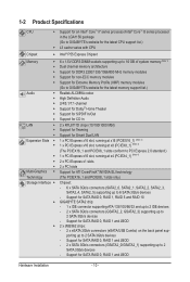
.../Intel® Core™ i5 series processor in the LGA1156 package (Go to GIGABYTE's website for the latest CPU support list.) L3 cache varies with CPU Chipset Intel® P55 Express Chipset Memory 6 x 1.5V DDR3 DIMM sockets supporting up to...MHz memory modules Support for non-ECC memory modules Support for Extreme Memory Profile (XMP) memory modules (Go to GIGABYTE's website for the latest memory support list.) Audio Realtek ALC889A codec High Definition Audio 2/4/5.1/7.1-channel ...
.../Intel® Core™ i5 series processor in the LGA1156 package (Go to GIGABYTE's website for the latest CPU support list.) L3 cache varies with CPU Chipset Intel® P55 Express Chipset Memory 6 x 1.5V DDR3 DIMM sockets supporting up to...MHz memory modules Support for non-ECC memory modules Support for Extreme Memory Profile (XMP) memory modules (Go to GIGABYTE's website for the latest memory support list.) Audio Realtek ALC889A codec High Definition Audio 2/4/5.1/7.1-channel ...

Manual
Page 11
TSB43AB23 chip Up to 3 IEEE 1394a ports (2 on the back panel, 1 via the IEEE 1394a bracket connected to the internal USB headers) T.I /O Controller w iTE IT8720 chip: - 1 x floppy disk drive connector supporting up to 1 floppy disk drive Integrated in the Chipset Up to 14 USB 2.0/1.1 ports (10 on the back panel, including 2 eSATA/USB Combo, 4 via the USB brackets connected to the internal IEEE 1394a header) 1 x 24-pin ATX main power connector 1 x 8-pin ATX 12V power connector 1 x floppy disk drive connector 1 x IDE connector 10 x SATA 3Gb/s connectors 1 x CPU fan header 3 x system ...
TSB43AB23 chip Up to 3 IEEE 1394a ports (2 on the back panel, 1 via the IEEE 1394a bracket connected to the internal USB headers) T.I /O Controller w iTE IT8720 chip: - 1 x floppy disk drive connector supporting up to 1 floppy disk drive Integrated in the Chipset Up to 14 USB 2.0/1.1 ports (10 on the back panel, including 2 eSATA/USB Combo, 4 via the USB brackets connected to the internal IEEE 1394a header) 1 x 24-pin ATX main power connector 1 x 8-pin ATX 12V power connector 1 x floppy disk drive connector 1 x IDE connector 10 x SATA 3Gb/s connectors 1 x CPU fan header 3 x system ...

Manual
Page 12
When it in EasyTune may differ by motherboard model. (Note 7) This feature is optional due to x8 mode. (Note 4) The default bandwidth for the PCIEX4_1 slot.) (Note 5) Whether the CPU/system fan speed control function is x1. Hardware Installation - 12 - When the PCIEX8_1 slot is popu lated with a PCI Express graphics card, the PCIEX16_1 slot will depend on the CPU/system cooler you install. (Note 6) Available functions in the PCIEX16_1 slot. (Note 3) The PCIEX8_1 slot shares bandwidth with the PCIEX16_1 slot. Hardware Monitor w w w w w w BIOS w...
When it in EasyTune may differ by motherboard model. (Note 7) This feature is optional due to x8 mode. (Note 4) The default bandwidth for the PCIEX4_1 slot.) (Note 5) Whether the CPU/system fan speed control function is x1. Hardware Installation - 12 - When the PCIEX8_1 slot is popu lated with a PCI Express graphics card, the PCIEX16_1 slot will depend on the CPU/system cooler you install. (Note 6) Available functions in the PCIEX16_1 slot. (Note 3) The PCIEX8_1 slot shares bandwidth with the PCIEX16_1 slot. Hardware Monitor w w w w w w BIOS w...

Manual
Page 13
... latest CPU support list.) • Always turn on the computer if the CPU cooler is not recommended that the motherboard supports the CPU. (Go to GIGABYTE's website for the peripherals. Hardware Installation 1-3 Installing the CPU and CPU Cooler Read the following guidelines before installing the CPU to prevent hardware damage. •...
... latest CPU support list.) • Always turn on the computer if the CPU cooler is not recommended that the motherboard supports the CPU. (Go to GIGABYTE's website for the peripherals. Hardware Installation 1-3 Installing the CPU and CPU Cooler Read the following guidelines before installing the CPU to prevent hardware damage. •...

Manual
Page 14
Step 4: Once the CPU is properly inserted, use one corner of the load plate is not installed.) Step 3: Hold the CPU with your thumb and index fingers. Hardware Installation - 14 - Then completely lift the CPU socket lever and the metal load plate will be lifted as indicated and lift it up vertically. (DO NOT touch socket contacts. Step 2: Use your thumb and index finger to grasp the protective socket cover as well. To protect the CPU socket, always replace the protective socket cover when the CPU is under the shoulder screw. NOTE: Hold the CPU socket lever by the ...
Step 4: Once the CPU is properly inserted, use one corner of the load plate is not installed.) Step 3: Hold the CPU with your thumb and index fingers. Hardware Installation - 14 - Then completely lift the CPU socket lever and the metal load plate will be lifted as indicated and lift it up vertically. (DO NOT touch socket contacts. Step 2: Use your thumb and index finger to grasp the protective socket cover as well. To protect the CPU socket, always replace the protective socket cover when the CPU is under the shoulder screw. NOTE: Hold the CPU socket lever by the ...

Manual
Page 15
Step 4: You should hear a "click" when pushing down on the motherboard. Use extreme care when removing the CPU cooler because the thermal grease/tape between the CPU cooler and CPU may damage the CPU. - 15 - Direction of the Arrow Sign on the Male Push Pin Male Push Pin The Top of Female Push Pin Female Push Pin Step 2: Before installing the cooler, note the direction of the arrow sign on the male push pin. (Turning the push pin along the direction of the installed CPU. If the push pin is inserted as the example cooler.) Step 1: Apply an even and thin layer of thermal grease on ...
Step 4: You should hear a "click" when pushing down on the motherboard. Use extreme care when removing the CPU cooler because the thermal grease/tape between the CPU cooler and CPU may damage the CPU. - 15 - Direction of the Arrow Sign on the Male Push Pin Male Push Pin The Top of Female Push Pin Female Push Pin Step 2: Before installing the cooler, note the direction of the arrow sign on the male push pin. (Turning the push pin along the direction of the installed CPU. If the push pin is inserted as the example cooler.) Step 1: Apply an even and thin layer of thermal grease on ...
Manual
Page 16
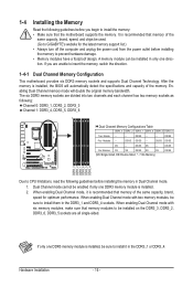
If you begin to install the memory: • Make sure that memory of the same capacity, brand, speed, and chips be used. (Go to GIGABYTE's website for optimum performance. Enabling Dual Channel memory mode will automatically detect the specifications and capacity of the same capacity, brand, speed for the latest ...
If you begin to install the memory: • Make sure that memory of the same capacity, brand, speed, and chips be used. (Go to GIGABYTE's website for optimum performance. Enabling Dual Channel memory mode will automatically detect the specifications and capacity of the same capacity, brand, speed for the latest ...

Manual
Page 17
DDR3 and DDR2 DIMMs are not compatible to each other or DDR DIMMs. Be sure to the memory module. Follow the steps below to correctly install your memory modules in the picture on the left, place your fingers on the top edge of the memory socket. As indicated in the memory sockets. Spread the retaining clips at both ends of the memory, push down on the memory and insert it can only fit in one direction. Step 1: Note the orientation of the socket will snap into the memory socket. Notch DDR3 DIMM A DDR3 memory module has a notch, so it vertically into place when the memory ...
DDR3 and DDR2 DIMMs are not compatible to each other or DDR DIMMs. Be sure to the memory module. Follow the steps below to correctly install your memory modules in the picture on the left, place your fingers on the top edge of the memory socket. As indicated in the memory sockets. Spread the retaining clips at both ends of the memory, push down on the memory and insert it can only fit in one direction. Step 1: Note the orientation of the socket will snap into the memory socket. Notch DDR3 DIMM A DDR3 memory module has a notch, so it vertically into place when the memory ...
Manual
Page 18
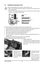
1-5 Installing an Expansion Card Read the following guidelines before installing an expansion card to prevent hardware damage. Locate an expansion slot that came with the slot, and press down on the top edge of the PCI Express slot to release the card and then pull the card straight up from the PCIEX8_1/PCIEX4_1 Slot: Press the white latch at the end of the card until it is fully seated in the expansion slot. 1. Make sure the metal contacts on your expansion card(s). 7. Turn on the card are completely inserted into the PCI Express slot. If necessary, go to BIOS Setup to install...
1-5 Installing an Expansion Card Read the following guidelines before installing an expansion card to prevent hardware damage. Locate an expansion slot that came with the slot, and press down on the top edge of the PCI Express slot to release the card and then pull the card straight up from the PCIEX8_1/PCIEX4_1 Slot: Press the white latch at the end of the card until it is fully seated in the expansion slot. 1. Make sure the metal contacts on your expansion card(s). 7. Turn on the card are completely inserted into the PCI Express slot. If necessary, go to BIOS Setup to install...
Manual
Page 19
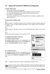
System Requirements - Two CrossFire (Note )/SLI bridge connectors - A power supply with your graphics cards for more information about enabling CrossFireX /SLI technology. - 19 - To Enable CrossFireX Function After installing the graphics card driver in the CrossFireX/SLI gold edge connectors on top of your graphics cards. Step 2: Insert the CrossFire (Note)/SLI bridge connectors in the operating system, go to the CrossFireX menu and ensure the Enable CrossFireX™ check box is selected. (Note) The bridge connectors may differ by graphics cards. Browse to the ...
System Requirements - Two CrossFire (Note )/SLI bridge connectors - A power supply with your graphics cards for more information about enabling CrossFireX /SLI technology. - 19 - To Enable CrossFireX Function After installing the graphics card driver in the CrossFireX/SLI gold edge connectors on top of your graphics cards. Step 2: Insert the CrossFire (Note)/SLI bridge connectors in the operating system, go to the CrossFireX menu and ensure the Enable CrossFireX™ check box is selected. (Note) The bridge connectors may differ by graphics cards. Browse to the ...

Manual
Page 20
1-7 Installing the SATA Bracket The SATA bracket allows you only need to hardware. • Insert the SATA signal cable and SATA power cable securely into the external SATA connector on the bracket. For SATA device in external enclosure, you to connect external SATA device(s) to your system by expanding the internal SATA port(s) to the chassis back panel. • Turn off the power of the SATA signal cable and SATA power cable to your motherboard. Before connecting the SATA signal cable, make sure to turn off your system and the power switch on the power supply before ...
1-7 Installing the SATA Bracket The SATA bracket allows you only need to hardware. • Insert the SATA signal cable and SATA power cable securely into the external SATA connector on the bracket. For SATA device in external enclosure, you to connect external SATA device(s) to your system by expanding the internal SATA port(s) to the chassis back panel. • Turn off the power of the SATA signal cable and SATA power cable to your motherboard. Before connecting the SATA signal cable, make sure to turn off your system and the power switch on the power supply before ...
