Manual
Page 5
...Appendix...85 5-1 Configuring SATA Hard Drive(s 85 5-1-1 Configuring Intel P55 SATA Controllers 85 5-1-2 Configuring JMB362/GIGABYTE SATA2 SATA Controller 93 5-1-3 Making a SATA RAID/AHCI Driver ...Audio Input and Output 111 5-2-1 Configuring 2/4/5.1/7.1-Channel Audio 111 5-2-2 Configuring S/PDIF In/Out 113 5-2-3 Enabling the Dolby Home Theater Functionj 115 5-2-4 Configuring Microphone Recording 116 5-2-5 Using the Sound Recorder 118 5-3 Troubleshooting 119 5-3-1 Frequently Asked Questions 119 5-3-2 Troubleshooting Procedure 120 5-4 Regulatory Statements 122 j Only for GA-P55-UD4P...
...Appendix...85 5-1 Configuring SATA Hard Drive(s 85 5-1-1 Configuring Intel P55 SATA Controllers 85 5-1-2 Configuring JMB362/GIGABYTE SATA2 SATA Controller 93 5-1-3 Making a SATA RAID/AHCI Driver ...Audio Input and Output 111 5-2-1 Configuring 2/4/5.1/7.1-Channel Audio 111 5-2-2 Configuring S/PDIF In/Out 113 5-2-3 Enabling the Dolby Home Theater Functionj 115 5-2-4 Configuring Microphone Recording 116 5-2-5 Using the Sound Recorder 118 5-3 Troubleshooting 119 5-3-1 Frequently Asked Questions 119 5-3-2 Troubleshooting Procedure 120 5-4 Regulatory Statements 122 j Only for GA-P55-UD4P...

Manual
Page 7
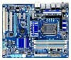
GA-P55-UD4P/GA-P55-UD4 Motherboard Layout KB_USB R_SPDIF CPU_FAN ATX_12V_2X4 USB_1394_ESATA_2 USB_1394_ESATA_1 LGA1156 USB_LAN2 j USB_LAN1 JMB362 RTL8111D AUDIO F_AUDIO SYS_FAN1 PCIEX1_1(Note) PCIEX16 RTL8111D j PCIEX1_2 CD_IN SPDIF_I SPDIF_O CODEC PCIEX1_3 PCIEX8 PCI1 BATTERY TPM IC j TSB43AB23 GA-P55-UD4P / GA-P55-UD4 DDR3_2 DDR3_1 PHASE LED ATX PWR_FAN IDE DDR3_4 DDR3_3 GIGABYTE SATA2 B_BIOS Intel® P55 M_BIOS SYS_FAN2 PCH_FAN CLR_CMOS GSATA2_1...
GA-P55-UD4P/GA-P55-UD4 Motherboard Layout KB_USB R_SPDIF CPU_FAN ATX_12V_2X4 USB_1394_ESATA_2 USB_1394_ESATA_1 LGA1156 USB_LAN2 j USB_LAN1 JMB362 RTL8111D AUDIO F_AUDIO SYS_FAN1 PCIEX1_1(Note) PCIEX16 RTL8111D j PCIEX1_2 CD_IN SPDIF_I SPDIF_O CODEC PCIEX1_3 PCIEX8 PCI1 BATTERY TPM IC j TSB43AB23 GA-P55-UD4P / GA-P55-UD4 DDR3_2 DDR3_1 PHASE LED ATX PWR_FAN IDE DDR3_4 DDR3_3 GIGABYTE SATA2 B_BIOS Intel® P55 M_BIOS SYS_FAN2 PCH_FAN CLR_CMOS GSATA2_1...

Manual
Page 10
... RAID 5, and RAID 10 GIGABYTE SATA2 chip: - 1 x IDE connector supporting ATA-133/100/66/33 and up to 2 IDE devices - 2 x SATA 3Gb/s connectors (GSATA2_0, GSATA2_1) supporting up to 1 floppy disk drive j Only for GA-P55-UD4P. Support for SATA RAID 0, RAID 1, ... Support for Extreme Memory Profile (XMP) memory modules (Go to GIGABYTE's website for the latest memory support list.) Audio Realtek ALC889A j/ALC888 k codec High Definition Audio 2/4/5.1/7.1-channel Support for Dolby® Home Theater j ...
... RAID 5, and RAID 10 GIGABYTE SATA2 chip: - 1 x IDE connector supporting ATA-133/100/66/33 and up to 2 IDE devices - 2 x SATA 3Gb/s connectors (GSATA2_0, GSATA2_1) supporting up to 1 floppy disk drive j Only for GA-P55-UD4P. Support for SATA RAID 0, RAID 1, ... Support for Extreme Memory Profile (XMP) memory modules (Go to GIGABYTE's website for the latest memory support list.) Audio Realtek ALC889A j/ALC888 k codec High Definition Audio 2/4/5.1/7.1-channel Support for Dolby® Home Theater j ...

Manual
Page 11
k Only for GA-P55-UD4P. Hardware Installation TSB43AB23 chip Up to 3 IEEE 1394a ports (2 on the back panel, 4 via the IEEE 1394a bracket connected to the internal USB headers) T.I. USB ... drive connector 1 x IDE connector 8 x SATA 3Gb/s connectors 1 x CPU fan header 2 x system fan headers 1 x power fan header 1 x PCH chip fan header 1 x front panel header 1 x front panel audio header 1 x CD In connector 1 x S/PDIF In header 1 x S/PDIF Out header 2 x USB 2.0/1.1 headers 1 x IEEE 1394a header 1 x serial port header 1 x parallel port header 1 x clearing CMOS jumper 1 x PS...
k Only for GA-P55-UD4P. Hardware Installation TSB43AB23 chip Up to 3 IEEE 1394a ports (2 on the back panel, 4 via the IEEE 1394a bracket connected to the internal USB headers) T.I. USB ... drive connector 1 x IDE connector 8 x SATA 3Gb/s connectors 1 x CPU fan header 2 x system fan headers 1 x power fan header 1 x PCH chip fan header 1 x front panel header 1 x front panel audio header 1 x CD In connector 1 x S/PDIF In header 1 x S/PDIF Out header 2 x USB 2.0/1.1 headers 1 x IEEE 1394a header 1 x serial port header 1 x parallel port header 1 x clearing CMOS jumper 1 x PS...

Manual
Page 20
... transmission or receiving is compatible with SATA 1.5Gb/s standard. Do not rock it straight out from the connector. Use this port for GA-P55-UD4P. • When removing the cable connected to a back panel connector, first remove the cable from your device and then remove it ...1394a device. 1-7 Back Panel Connectors j USB Port The USB port supports the USB 2.0/1.1 specification. Coaxial S/PDIF Out Connector This connector provides digital audio out to 1 Gbps data rate. eSATA 3Gb/s Port The eSATA 3Gb/s port conforms to Chapter 5, "Configuring SATA Hard Drive(s)," for USB devices...
... transmission or receiving is compatible with SATA 1.5Gb/s standard. Do not rock it straight out from the connector. Use this port for GA-P55-UD4P. • When removing the cable connected to a back panel connector, first remove the cable from your device and then remove it ...1394a device. 1-7 Back Panel Connectors j USB Port The USB port supports the USB 2.0/1.1 specification. Coaxial S/PDIF Out Connector This connector provides digital audio out to 1 Gbps data rate. eSATA 3Gb/s Port The eSATA 3Gb/s port conforms to Chapter 5, "Configuring SATA Hard Drive(s)," for USB devices...

Manual
Page 21
... rear speakers in jack. Use this audio jack for GA-P55-UD4P. Microphones must be connected to the default Mic in devices such as an optical drive, walkman, etc. Line Out Jack (Green) The default line out jack. figuration in a 5.1/7.1-channel audio configuration. Hardware Installation Use this audio jack for GA-P55-UD4. - 21 - k Only for a headphone or...
... rear speakers in jack. Use this audio jack for GA-P55-UD4P. Microphones must be connected to the default Mic in devices such as an optical drive, walkman, etc. Line Out Jack (Green) The default line out jack. figuration in a 5.1/7.1-channel audio configuration. Hardware Installation Use this audio jack for GA-P55-UD4. - 21 - k Only for a headphone or...

Manual
Page 28
... GND 6 NC 7 FAUDIO_JD 7 NC 8 No Pin 8 No Pin 9 LINE2_L 9 Line Out (L) 10 GND 10 NC • The front panel audio header supports HD audio by default. Pin No. Make sure the wire assignments of the module connector match the pin assignments of a single plug. If your optical drive...be present on each wire instead of the motherboard header. Definition Pin No. 12) F_AUDIO (Front Panel Audio Header) The front panel audio header supports Intel High Definition audio (HD) and AC'97 audio. Definition 1 CD-L 2 GND 3 GND 1 4 CD-R Hardware Installation - 28 - If you want...
... GND 6 NC 7 FAUDIO_JD 7 NC 8 No Pin 8 No Pin 9 LINE2_L 9 Line Out (L) 10 GND 10 NC • The front panel audio header supports HD audio by default. Pin No. Make sure the wire assignments of the module connector match the pin assignments of a single plug. If your optical drive...be present on each wire instead of the motherboard header. Definition Pin No. 12) F_AUDIO (Front Panel Audio Header) The front panel audio header supports Intel High Definition audio (HD) and AC'97 audio. Definition 1 CD-L 2 GND 3 GND 1 4 CD-R Hardware Installation - 28 - If you want...

Manual
Page 29
... you to use a S/PDIF digital audio cable for your motherboard to an audio device that supports digital audio out via an optional S/PDIF In cable. For information about connecting the S/PDIF digital audio cable, carefully read the manual for digital audio output from your motherboard to your graphics... card if you wish to connect an HDMI display to the graphics card and have digital audio output from your expansion card. Hardware Installation For purchasing the optional S/PDIF In cable, please contact the local dealer. Definition 1 SPDIFO 2 GND 1...
... you to use a S/PDIF digital audio cable for your motherboard to an audio device that supports digital audio out via an optional S/PDIF In cable. For information about connecting the S/PDIF digital audio cable, carefully read the manual for digital audio output from your motherboard to your graphics... card if you wish to connect an HDMI display to the graphics card and have digital audio output from your expansion card. Hardware Installation For purchasing the optional S/PDIF In cable, please contact the local dealer. Definition 1 SPDIFO 2 GND 1...

Manual
Page 38
... defaults are factory settings for the most stable, minimal-performance system operations. Load Optimized Defaults Optimized defaults are factory settings for GA-P55-UD4P. First select the profile you to restrict access to a profile. It allows you can also carry out this task.) Exit... the primary display adapter. Integrated Peripherals Use this menu to configure all peripheral devices, such as IDE, SATA, USB, integrated audio, and integrated LAN, etc. Power Management Setup Use this menu to configure the system time and date, hard drive types, floppy...
... defaults are factory settings for the most stable, minimal-performance system operations. Load Optimized Defaults Optimized defaults are factory settings for GA-P55-UD4P. First select the profile you to restrict access to a profile. It allows you can also carry out this task.) Exit... the primary display adapter. Integrated Peripherals Use this menu to configure all peripheral devices, such as IDE, SATA, USB, integrated audio, and integrated LAN, etc. Power Management Setup Use this menu to configure the system time and date, hard drive types, floppy...

Manual
Page 54
...USB Legacy Function Allows USB keyboard to Disabled. BIOS Setup - 54 - Set this item to be disabled automatically. (Default: Disabled) j Only for GA-P55-UD4P. Onboard H/W 1394 Enables or disables the onboard IEEE 1394 function. (Default: Enabled) Onboard H/W LAN1/LAN2 j Enables or disables the onboard LAN function....a LAN cable is connected or not. Enable Native IDE mode if you wish to install a 3rd party add-in audio card instead of using the onboard audio, set this item to operate in Legacy IDE mode. Green LAN When the onboard LAN function and Green LAN are ...
...USB Legacy Function Allows USB keyboard to Disabled. BIOS Setup - 54 - Set this item to be disabled automatically. (Default: Disabled) j Only for GA-P55-UD4P. Onboard H/W 1394 Enables or disables the onboard IEEE 1394 function. (Default: Enabled) Onboard H/W LAN1/LAN2 j Enables or disables the onboard LAN function....a LAN cable is connected or not. Enable Native IDE mode if you wish to install a 3rd party add-in audio card instead of using the onboard audio, set this item to operate in Legacy IDE mode. Green LAN When the onboard LAN function and Green LAN are ...

Manual
Page 111
..., you want to mute the back panel audio (only supported when using an HD front panel audio module), refer to instructions on the back panel which support 2/4/5.1/7.1-channel (Note) audio. Configuring Speakers (The following for GA-P55-UD4P. all at the same time. The integrated... HD (High Definition) audio provides jack retasking capability that allows the user to MP3 music, have an Internet chat...
..., you want to mute the back panel audio (only supported when using an HD front panel audio module), refer to instructions on the back panel which support 2/4/5.1/7.1-channel (Note) audio. Configuring Speakers (The following for GA-P55-UD4P. all at the same time. The integrated... HD (High Definition) audio provides jack retasking capability that allows the user to MP3 music, have an Internet chat...

Manual
Page 112
... the type of speaker configuration you connect. B. The The current connected device is completed. Configuring Sound Effect You may configure an audio environment on the Speaker Configuration tab to complete. On the Connector Settings dialog box, select the Disable front panel jack detection check ...the Speakers screen, click the Speaker Configuration tab. Click OK to open the Device advanced settings dialog box. Muting the Back Panel Audio (For HD Audio Only) Click Device advanced settings on the top right corner on the Sound Effects tab. Select the Mute the rear output device...
... the type of speaker configuration you connect. B. The The current connected device is completed. Configuring Sound Effect You may configure an audio environment on the Speaker Configuration tab to complete. On the Connector Settings dialog box, select the Disable front panel jack detection check ...the Speakers screen, click the Speaker Configuration tab. Click OK to open the Device advanced settings dialog box. Muting the Back Panel Audio (For HD Audio Only) Click Device advanced settings on the top right corner on the Sound Effects tab. Select the Mute the rear output device...

Manual
Page 113
... 2: Secure the metal bracket to select the default format. Click OK to complete. (Note) The actual locations of the cable to the computer for audio processing. Configuring S/PDIF In: On the Digital Input screen, click the Default Format tab to the chassis back panel with a screw. 2. S/PDIF In... The S/PDIF In cable (optional) allows you to input digital audio signals to the SPDIF_I header on your motherboard. Installing the S/PDIF In Cable: Step 1: First, attach the connector at the end of the S/PDIF...
... 2: Secure the metal bracket to select the default format. Click OK to complete. (Note) The actual locations of the cable to the computer for audio processing. Configuring S/PDIF In: On the Digital Input screen, click the Default Format tab to the chassis back panel with a screw. 2. S/PDIF In... The S/PDIF In cable (optional) allows you to input digital audio signals to the SPDIF_I header on your motherboard. Installing the S/PDIF In Cable: Step 1: First, attach the connector at the end of the S/PDIF...

Manual
Page 114
Appendix - 114 - Click OK to an external decoder for decoding to get the best audio quality. 1. Configuring S/PDIF Out: On the Digital Output screen, click the Default Format tab and then select the sample rate and bit depth. Connecting a S/PDIF Out Cable: S/PDIF Coaxial Cable S/PDIF Optical Cable Connect a S/PDIF coaxial cable or a S/PDIF optical cable (either one) to complete. B. S/PDIF Out The S/PDIF Out jacks can transmit audio signals to an external decoder for transmitting the S/PDIF digital audio signals. 2.
Appendix - 114 - Click OK to an external decoder for decoding to get the best audio quality. 1. Configuring S/PDIF Out: On the Digital Output screen, click the Default Format tab and then select the sample rate and bit depth. Connecting a S/PDIF Out Cable: S/PDIF Coaxial Cable S/PDIF Optical Cable Connect a S/PDIF coaxial cable or a S/PDIF optical cable (either one) to complete. B. S/PDIF Out The S/PDIF Out jacks can transmit audio signals to an external decoder for transmitting the S/PDIF digital audio signals. 2.

Manual
Page 115
... to All 1. : Click Dolby Pro Logic IIx. With Dolby Home Theater enabled, 2-channel stereo content will expand 2-channel audio for GA-P55-UD4P. Appendix 5-2-3 Enabling the Dolby Home Theater Functionj Before Dolby Home Theater is working, and you get 4-, 5.1-, or 7.1- channel... audio effects. channel content to access the utility. (The following illustration demonstrates a 7.1-speaker configuration as an example.) . Point...
... to All 1. : Click Dolby Pro Logic IIx. With Dolby Home Theater enabled, 2-channel stereo content will expand 2-channel audio for GA-P55-UD4P. Appendix 5-2-3 Enabling the Dolby Home Theater Functionj Before Dolby Home Theater is working, and you get 4-, 5.1-, or 7.1- channel... audio effects. channel content to access the utility. (The following illustration demonstrates a 7.1-speaker configuration as an example.) . Point...

Manual
Page 116
5-2-4 Configuring Microphone Recording Step 1: After installing the audio driver, the HD Audio Manager icon will appear in jack (pink) on the front panel. Step 3: Go to the Mic in jack (pink) on the back panel or the ... change the current sound input default device to microphone, right-click on the front panel and back panel cannot be able to access the HD Audio Manager. To hear the sound being recorded during the recording process, do not mute the playback volume. If you set the volumes at the same...
5-2-4 Configuring Microphone Recording Step 1: After installing the audio driver, the HD Audio Manager icon will appear in jack (pink) on the front panel. Step 3: Go to the Mic in jack (pink) on the back panel or the ... change the current sound input default device to microphone, right-click on the front panel and back panel cannot be able to access the HD Audio Manager. To hear the sound being recorded during the recording process, do not mute the playback volume. If you set the volumes at the same...

Manual
Page 117
..., click Start, point to All Programs, point to Accessories, and then click Sound Recorder to begin the sound recording. * Enabling Stereo Mix If the HD Audio Manager does not display the recording device you want to the steps below. Step 2: On the Recording tab, right-click on this icon. The following...
..., click Start, point to All Programs, point to Accessories, and then click Sound Recorder to begin the sound recording. * Enabling Stereo Mix If the HD Audio Manager does not display the recording device you want to the steps below. Step 2: On the Recording tab, right-click on this icon. The following...

Manual
Page 118
... item and select Enable. To record the audio, click the Start Recording button . 3. Make sure you can play your recording in a digital media player program that supports your audio file format. microphone) to save the recorded audio file upon completion. B. Recording Sound 1. ...Appendix - 118 - To stop recording audio, click the Stop Recording button . Playing the Recorded Sound You can...
... item and select Enable. To record the audio, click the Start Recording button . 3. Make sure you can play your recording in a digital media player program that supports your audio file format. microphone) to save the recorded audio file upon completion. B. Recording Sound 1. ...Appendix - 118 - To stop recording audio, click the Stop Recording button . Playing the Recorded Sound You can...
Manual
Page 119
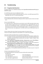
... clear the CMOS values? Appendix 5-3 Troubleshooting 5-3-1 Frequently Asked Questions To read more details, go to the Support&Downloads\Motherboard\FAQ page on GIGABYTE's website. Q: Why is equipped with power/amplifier. For more FAQs for your motherboard, please go to the Support&Downloads\Motherboards\FAQ page... on the computer name and select Scan for "onboard HD audio driver." Then install the onboard HD audio driver from the motherboard driver disk or download the audio driver from GIGABYTE's website to clear the CMOS values (before doing this, please turn ...
... clear the CMOS values? Appendix 5-3 Troubleshooting 5-3-1 Frequently Asked Questions To read more details, go to the Support&Downloads\Motherboard\FAQ page on GIGABYTE's website. Q: Why is equipped with power/amplifier. For more FAQs for your motherboard, please go to the Support&Downloads\Motherboards\FAQ page... on the computer name and select Scan for "onboard HD audio driver." Then install the onboard HD audio driver from the motherboard driver disk or download the audio driver from GIGABYTE's website to clear the CMOS values (before doing this, please turn ...


