
Manual
Page 1
...: Click Cancel to exit the X.H.D utility. (Note 1) The X.H.D utility only supports the SATA controllers integrated in the array. ) 1. A. Using GIGABYTE eXtreme Hard Drive (X.H.D) Instructions:(Note 2) Before launching X.H.D, make sure the new drive is greater than or equal to the biggest drive in the Intel ... utility, back up a RAID 0 array later using the Auto function. Setting Up a RAID-Ready System Step 1: Configure the system BIOS Enter the system BIOS Setup program, set up a RAID-ready system and configure it for RAID 0 when a new SATA drive is recommended that already exists...
...: Click Cancel to exit the X.H.D utility. (Note 1) The X.H.D utility only supports the SATA controllers integrated in the array. ) 1. A. Using GIGABYTE eXtreme Hard Drive (X.H.D) Instructions:(Note 2) Before launching X.H.D, make sure the new drive is greater than or equal to the biggest drive in the Intel ... utility, back up a RAID 0 array later using the Auto function. Setting Up a RAID-Ready System Step 1: Configure the system BIOS Enter the system BIOS Setup program, set up a RAID-ready system and configure it for RAID 0 when a new SATA drive is recommended that already exists...
Manual
Page 3
... and is 1.0. No part of this manual may be reproduced, copied, translated, transmitted, or published in the use GIGABYTE's unique features, read or download the information on/from the Support&Downloads\Motherboard\Technology Guide page on your motherboard revision before updating... motherboard BIOS, drivers, or when looking for technical information. For detailed product information, carefully read the Quick Installation Guide included with ...
... and is 1.0. No part of this manual may be reproduced, copied, translated, transmitted, or published in the use GIGABYTE's unique features, read or download the information on/from the Support&Downloads\Motherboard\Technology Guide page on your motherboard revision before updating... motherboard BIOS, drivers, or when looking for technical information. For detailed product information, carefully read the Quick Installation Guide included with ...
Manual
Page 4
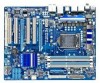
Table of Contents Box Contents...6 Optional Items...6 GA-P55-UD3P/GA-P55-UD3R Motherboard Layout 7 Block Diagram...8 Chapter 1 Hardware Installation 9 1-1 Installation Precautions 9 1-2 Product Specifications 10 1-3 Installing the CPU and CPU Cooler... Installing an Expansion Card 18 1-6 Back Panel Connectors 19 1-7 Internal Connectors 21 Chapter 2 BIOS Setup 33 2-1 Startup Screen 34 2-2 The Main Menu 35 2-3 MB Intelligent Tweaker(M.I.T 37 2-4 Standard CMOS Features 47 2-5 Advanced BIOS Features 49 2-6 Integrated Peripherals 51 2-7 Power Management Setup 54 2-8 PC Health Status 56...
Table of Contents Box Contents...6 Optional Items...6 GA-P55-UD3P/GA-P55-UD3R Motherboard Layout 7 Block Diagram...8 Chapter 1 Hardware Installation 9 1-1 Installation Precautions 9 1-2 Product Specifications 10 1-3 Installing the CPU and CPU Cooler... Installing an Expansion Card 18 1-6 Back Panel Connectors 19 1-7 Internal Connectors 21 Chapter 2 BIOS Setup 33 2-1 Startup Screen 34 2-2 The Main Menu 35 2-3 MB Intelligent Tweaker(M.I.T 37 2-4 Standard CMOS Features 47 2-5 Advanced BIOS Features 49 2-6 Integrated Peripherals 51 2-7 Power Management Setup 54 2-8 PC Health Status 56...
Manual
Page 5
...4-2-1 Updating the BIOS with the Q-Flash Utility 70 4-2-2 Updating the BIOS with the @BIOS Utility 73 4-3 EasyTune 6...74 4-4 Dynamic Energy Saver™ 2 75 4-5 Q-Share...77 4-6 Smart 6™ ...78 4-7 Smart TPM j 81 Chapter 5 Appendix...83 5-1 Configuring SATA Hard Drive(s 83 5-1-1 Configuring Intel P55 SATA Controllers 83 5-1-2 Configuring JMB362/GIGABYTE SATA2 SATA Controller... 113 5-2-4 Using the Sound Recorder 115 5-3 Troubleshooting 116 5-3-1 Frequently Asked Questions 116 5-3-2 Troubleshooting Procedure 117 5-4 Regulatory Statements 119 j Only for GA-P55-UD3P. - 5 -
...4-2-1 Updating the BIOS with the Q-Flash Utility 70 4-2-2 Updating the BIOS with the @BIOS Utility 73 4-3 EasyTune 6...74 4-4 Dynamic Energy Saver™ 2 75 4-5 Q-Share...77 4-6 Smart 6™ ...78 4-7 Smart TPM j 81 Chapter 5 Appendix...83 5-1 Configuring SATA Hard Drive(s 83 5-1-1 Configuring Intel P55 SATA Controllers 83 5-1-2 Configuring JMB362/GIGABYTE SATA2 SATA Controller... 113 5-2-4 Using the Sound Recorder 115 5-3 Troubleshooting 116 5-3-1 Frequently Asked Questions 116 5-3-2 Troubleshooting Procedure 117 5-4 Regulatory Statements 119 j Only for GA-P55-UD3P. - 5 -
Manual
Page 8
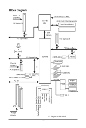
... (100 MHz) x1 1 PCI Express x1 2 SATA 3Gb/s ATA-133/100/66/33 IDE Channel PCI Bus GIGABYTE SATA2 DMI Interface 1 PCI Express x4 Intel® P55 x4 PCI Express Bus x1 2 SATA 3Gb/s Dual BIOS JMB362 6 SATA 3Gb/s 14 USB Ports CODEC LPC Bus IT8720 Floppy COM Port PS/2 KB/Mouse TPM... j Surround Speaker Out Center/Subwoofer Speaker Out Side Speaker Out MIC Line Out Line In S/PDIF In S/PDIF Out 4 PCI PCI CLK (33 MHz) j Only for GA-P55-UD3P. - 8 -
... (100 MHz) x1 1 PCI Express x1 2 SATA 3Gb/s ATA-133/100/66/33 IDE Channel PCI Bus GIGABYTE SATA2 DMI Interface 1 PCI Express x4 Intel® P55 x4 PCI Express Bus x1 2 SATA 3Gb/s Dual BIOS JMB362 6 SATA 3Gb/s 14 USB Ports CODEC LPC Bus IT8720 Floppy COM Port PS/2 KB/Mouse TPM... j Surround Speaker Out Center/Subwoofer Speaker Out Side Speaker Out MIC Line Out Line In S/PDIF In S/PDIF Out 4 PCI PCI CLK (33 MHz) j Only for GA-P55-UD3P. - 8 -
Manual
Page 11
...-45 port 6 x audio jacks (Center/Subwoofer Speaker Out/Rear Speaker Out/ Side Speaker Out/Line In/Line Out/Microphone) I/O Controller w iTE IT8720 chip Hardware Monitor w w w w w w BIOS w w w w System voltage detection CPU/System temperature detection CPU/System/Power fan speed detection CPU overheating warning CPU/System/Power fan fail warning CPU/System fan...
...-45 port 6 x audio jacks (Center/Subwoofer Speaker Out/Rear Speaker Out/ Side Speaker Out/Line In/Line Out/Microphone) I/O Controller w iTE IT8720 chip Hardware Monitor w w w w w w BIOS w w w w System voltage detection CPU/System temperature detection CPU/System/Power fan speed detection CPU overheating warning CPU/System/Power fan fail warning CPU/System fan...
Manual
Page 12
... - 12 - Unique Features w w w w w w w w w w w Bundled Software w Support for @BIOS Support for Q-Flash Support for Xpress BIOS Rescue Support for Download Center Support for Xpress Install Support for Xpress Recovery2 Support for EasyTune (Note 5) Support for Dynamic ... System w Support for Microsoft® Windows® 7/Vista/XP Form Factor w ATX Form Factor; 30.5cm x 24.4cm j Only for GA-P55-UD3P. (Note 1) Due to Windows Vista/XP 32-bit operating system limitation, when more than 4 GB of physical memory is installed, the ...
... - 12 - Unique Features w w w w w w w w w w w Bundled Software w Support for @BIOS Support for Q-Flash Support for Xpress BIOS Rescue Support for Download Center Support for Xpress Install Support for Xpress Recovery2 Support for EasyTune (Note 5) Support for Dynamic ... System w Support for Microsoft® Windows® 7/Vista/XP Form Factor w ATX Form Factor; 30.5cm x 24.4cm j Only for GA-P55-UD3P. (Note 1) Due to Windows Vista/XP 32-bit operating system limitation, when more than 4 GB of physical memory is installed, the ...
Manual
Page 16
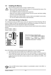
... Channel mode with two memory modules, be enabled if only one DDR3 memory module is installed, it is recommended to install it is installed, the BIOS will double the original memory bandwidth. If only one DDR3 memory module is recommended that memory of the same capacity, brand, speed, and chips be... following: Channel 0: DDR3_1, DDR3_2 Channel 1: DDR3_3, DDR3_4 Dual Channel Memory Configurations Table DDR3_2 DDR3_1 DDR3_4 DDR3_3 Two Modules - - A memory module can be used . (Go to GIGABYTE's website for optimum performance.
... Channel mode with two memory modules, be enabled if only one DDR3 memory module is installed, it is recommended to install it is installed, the BIOS will double the original memory bandwidth. If only one DDR3 memory module is recommended that memory of the same capacity, brand, speed, and chips be... following: Channel 0: DDR3_1, DDR3_2 Channel 1: DDR3_3, DDR3_4 Dual Channel Memory Configurations Table DDR3_2 DDR3_1 DDR3_4 DDR3_3 Two Modules - - A memory module can be used . (Go to GIGABYTE's website for optimum performance.
Manual
Page 18
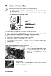
... to correctly install your expansion card(s). 7. Turn on the card until it is fully inserted into the slot. 4. If necessary, go to BIOS Setup to release the card and then pull the card straight up from the chassis back panel. 2. Make sure the metal contacts on the ...top edge of the PCI Express slot to make any required BIOS changes for your expansion card in the expansion slot. 1. After installing all expansion cards, replace the chassis cover(s). 6. Example: Installing and Removing a...
... to correctly install your expansion card(s). 7. Turn on the card until it is fully inserted into the slot. 4. If necessary, go to BIOS Setup to release the card and then pull the card straight up from the chassis back panel. 2. Make sure the metal contacts on the ...top edge of the PCI Express slot to make any required BIOS changes for your expansion card in the expansion slot. 1. After installing all expansion cards, replace the chassis cover(s). 6. Example: Installing and Removing a...
Manual
Page 25
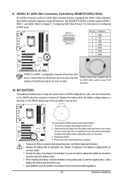
... If more than two hard drives are to be used, the total number of the battery holder, making them short for 5 seconds.) 3. The GIGABYTE SATA2 controller supports RAID 0, RAID 1, and JBOD. Refer to Chapter 5, "Configuring SATA Hard Drive(s)," for one . Replace the battery when the battery...wait for instructions on configuring a RAID array. Please connect the L-shaped end of the SATA 3Gb/s cable to keep the values (such as BIOS configurations, date, and time information) in the CMOS when the computer is replaced with SATA 1.5Gb/s standard. Turn off . Danger of ...
... If more than two hard drives are to be used, the total number of the battery holder, making them short for 5 seconds.) 3. The GIGABYTE SATA2 controller supports RAID 0, RAID 1, and JBOD. Refer to Chapter 5, "Configuring SATA Hard Drive(s)," for one . Replace the battery when the battery...wait for instructions on configuring a RAID array. Please connect the L-shaped end of the SATA 3Gb/s cable to keep the values (such as BIOS configurations, date, and time information) in the CMOS when the computer is replaced with SATA 1.5Gb/s standard. Turn off . Danger of ...
Manual
Page 26
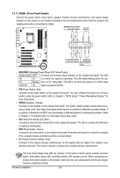
... on the chassis front panel. The system reports system startup status by chassis. When connecting your system using the power switch (refer to Chapter 2, "BIOS Setup," "Power Management Setup," for information about beep codes. • HD (Hard Drive Activity LED, Blue) Connects to the power switch on the...on the chassis to this header, make sure the wire assignments and the pin assignments are matched correctly. The LED S0 On is detected, the BIOS may issue beeps in S1 sleep state. You may differ by issuing a beep code. If a problem is on the chassis front panel. ...
... on the chassis front panel. The system reports system startup status by chassis. When connecting your system using the power switch (refer to Chapter 2, "BIOS Setup," "Power Management Setup," for information about beep codes. • HD (Hard Drive Activity LED, Blue) Connects to the power switch on the...on the chassis to this header, make sure the wire assignments and the pin assignments are matched correctly. The LED S0 On is detected, the BIOS may issue beeps in S1 sleep state. You may differ by issuing a beep code. If a problem is on the chassis front panel. ...
Manual
Page 30
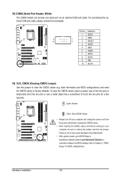
... the CMOS values and before turning on the two pins to temporarily short the two pins or use a metal object like a screwdriver to Chapter 2, "BIOS Setup," for a few seconds. Failure to do so may cause damage to the motherboard. • After system restart, go to... BIOS Setup to load factory defaults (select Load Optimized Defaults) or manually configure the BIOS settings (refer to touch the two pins for BIOS configurations). For purchasing the optional COM port cable, please contact the local dealer. Pin ...
... the CMOS values and before turning on the two pins to temporarily short the two pins or use a metal object like a screwdriver to Chapter 2, "BIOS Setup," for a few seconds. Failure to do so may cause damage to the motherboard. • After system restart, go to... BIOS Setup to load factory defaults (select Load Optimized Defaults) or manually configure the BIOS settings (refer to touch the two pins for BIOS configurations). For purchasing the optional COM port cable, please contact the local dealer. Pin ...
Manual
Page 33
...startup, saving system parameters and loading operating system, etc. Chapter 2 BIOS Setup BIOS (Basic Input and Output System) records hardware parameters of BIOS, it with caution. To upgrade the BIOS, use either the GIGABYTE Q-Flash or @BIOS utility. • Q-Flash allows the user to quickly and easily ...upgrade or back up BIOS without entering the operating system. • @BIOS is turned on the motherboard...
...startup, saving system parameters and loading operating system, etc. Chapter 2 BIOS Setup BIOS (Basic Input and Output System) records hardware parameters of BIOS, it with caution. To upgrade the BIOS, use either the GIGABYTE Q-Flash or @BIOS utility. • Q-Flash allows the user to quickly and easily ...upgrade or back up BIOS without entering the operating system. • @BIOS is turned on the motherboard...

Manual
Page 34
... the instructions on the Full Screen LOGO Show item on BIOS Setup settings. To show the BIOS POST screen. The system will still be used for one time only. Motherboard Model BIOS Version P55-UD3P D6 . . . . : BIOS Setup : XpressRecovery2 : Boot Menu : Qflash 07/08/2009-P55-7A89RG0JC-00 Function Keys Function Keys Function Keys: : POST SCREEN...
... the instructions on the Full Screen LOGO Show item on BIOS Setup settings. To show the BIOS POST screen. The system will still be used for one time only. Motherboard Model BIOS Version P55-UD3P D6 . . . . : BIOS Setup : XpressRecovery2 : Boot Menu : Qflash 07/08/2009-P55-7A89RG0JC-00 Function Keys Function Keys Function Keys: : POST SCREEN...
Manual
Page 35
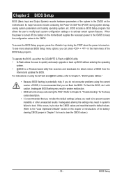
...among the items and press to accept or enter a sub-menu. (Sample BIOS Version: GA-P55-UD3P D6) CMOS Setup Utility-Copyright (C) 1984-2009 Award Software MB Intelligent Tweaker(M.I.T.) Standard CMOS Features Advanced BIOS Features Integrated Peripherals Power Management Setup PC ... of the submenu. • If you do not find the settings you enter the BIOS Setup program, the Main Menu (as shown below) appears on the bottom line of function keys available for GA-P55-UD3P. - 35 - Submenu Help While in a submenu, press to display a help...
...among the items and press to accept or enter a sub-menu. (Sample BIOS Version: GA-P55-UD3P D6) CMOS Setup Utility-Copyright (C) 1984-2009 Award Software MB Intelligent Tweaker(M.I.T.) Standard CMOS Features Advanced BIOS Features Integrated Peripherals Power Management Setup PC ... of the submenu. • If you do not find the settings you enter the BIOS Setup program, the Main Menu (as shown below) appears on the bottom line of function keys available for GA-P55-UD3P. - 35 - Submenu Help While in a submenu, press to display a help...
Manual
Page 36
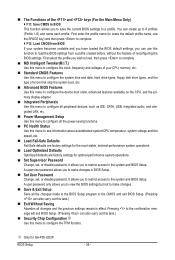
...Use this menu to configure the clock, frequency and voltages of your system becomes unstable and you have loaded the BIOS default settings, you can also carry out this menu to configure the system time and date, hard drive types,... enter the profile name (to erase the default profile name, use this function to complete. F12: Load CMOS from BIOS If your CPU, memory, etc. Standard CMOS Features Use this task.) Exit Without Saving Abandon all the ... system operations. Load Optimized Defaults Optimized defaults are factory settings for GA-P55-UD3P.
...Use this menu to configure the clock, frequency and voltages of your system becomes unstable and you have loaded the BIOS default settings, you can also carry out this menu to configure the system time and date, hard drive types,... enter the profile name (to erase the default profile name, use this function to complete. F12: Load CMOS from BIOS If your CPU, memory, etc. Standard CMOS Features Use this task.) Exit Without Saving Abandon all the ... system operations. Load Optimized Defaults Optimized defaults are factory settings for GA-P55-UD3P.

Manual
Page 37
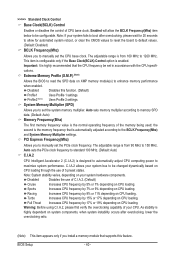
BIOS Setup For more information about Intel CPUs' unique features, please visit Intel's website. (Note 2) This item appears only if you not to alter the default ... Frequency Settings } Advanced Memory Settings } Advanced Voltage Settings } Miscellaneous Settings [Press Enter] [Press Enter] [Press Enter] [Press Enter] [Press Enter] Item Help Menu Level BIOS Version BCLK CPU Frequency Memory Frequency Total Memory Size D6 133.27 MHz 3198.42 MHz 1332.80 MHz 1024 MB CPU Temperature PCH Temperature...
BIOS Setup For more information about Intel CPUs' unique features, please visit Intel's website. (Note 2) This item appears only if you not to alter the default ... Frequency Settings } Advanced Memory Settings } Advanced Voltage Settings } Miscellaneous Settings [Press Enter] [Press Enter] [Press Enter] [Press Enter] [Press Enter] Item Help Menu Level BIOS Version BCLK CPU Frequency Memory Frequency Total Memory Size D6 133.27 MHz 3198.42 MHz 1332.80 MHz 1024 MB CPU Temperature PCH Temperature...
Manual
Page 38
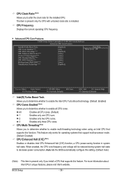
...whether to enable all CPU cores. (Default) 1 Enables only one CPU core. 2 Enables only two CPU cores. 3 Enables only three CPU cores. BIOS Setup - 38 - CPU Cores Enabled (Note) CPU Multi-Threading (Note) CPU Enhanced Halt (C1E) (Note) C3/C6/C7 State Support (Note)...; Advanced CPU Core Features CMOS Setup Utility-Copyright (C) 1984-2009 Award Software Advanced CPU Core Features Intel(R) Turbo Boost Tech. Auto lets the BIOS automatically configure this function. CPU Multi-Threading (Note) Allows you install a CPU that supports this setting. (Default: Auto) (Note) This ...
...whether to enable all CPU cores. (Default) 1 Enables only one CPU core. 2 Enables only two CPU cores. 3 Enables only three CPU cores. BIOS Setup - 38 - CPU Cores Enabled (Note) CPU Multi-Threading (Note) CPU Enhanced Halt (C1E) (Note) C3/C6/C7 State Support (Note)...; Advanced CPU Core Features CMOS Setup Utility-Copyright (C) 1984-2009 Award Software Advanced CPU Core Features Intel(R) Turbo Boost Tech. Auto lets the BIOS automatically configure this function. CPU Multi-Threading (Note) Allows you install a CPU that supports this setting. (Default: Auto) (Note) This ...

Manual
Page 39
... allows the CPU to detect whether an overheating is present only if you install a CPU that an overheating is overheated. BIOS Setup Depending on CPU loading, Intel EIST technology can function as multiple virtual systems. (Default: Enabled) QPI Clock Ratio Allows...CPU EIST Function (Note) Enables or disables Enhanced Intel SpeedStep Technology (EIST). Auto lets the BIOS automatically configure this setting. (Default: Auto) Bi-Directional PROCHOT (Note) Auto Lets BIOS automatically configure this setting. (Default) Enabled When the CPU or chipset detects that supports this ...
... allows the CPU to detect whether an overheating is present only if you install a CPU that an overheating is overheated. BIOS Setup Depending on CPU loading, Intel EIST technology can function as multiple virtual systems. (Default: Enabled) QPI Clock Ratio Allows...CPU EIST Function (Note) Enables or disables Enhanced Intel SpeedStep Technology (EIST). Auto lets the BIOS automatically configure this setting. (Default: Auto) Bi-Directional PROCHOT (Note) Auto Lets BIOS automatically configure this setting. (Default) Enabled When the CPU or chipset detects that supports this ...
Manual
Page 40
..., please wait for 20 seconds to allow the BCLK Frequency(Mhz) item below to be configurable. Extreme Memory Profile (X.M.P.) (Note) Allows the BIOS to read the SPD data on XMP memory module(s) to memory SPD data. (Default: Auto) Memory Frequency(Mhz) The first memory frequency value... on CPU loading. The adjustable range is from 100 MHz to 150 MHz. Sports Increases CPU frequency by 9% or 11% depending on CPU loading. BIOS Setup - 40 - Profile2 (Note) Uses Profile 2 settings. Disabled Disables the use of CPU base clock. This item is configurable only if the...
..., please wait for 20 seconds to allow the BCLK Frequency(Mhz) item below to be configurable. Extreme Memory Profile (X.M.P.) (Note) Allows the BIOS to read the SPD data on XMP memory module(s) to memory SPD data. (Default: Auto) Memory Frequency(Mhz) The first memory frequency value... on CPU loading. The adjustable range is from 100 MHz to 150 MHz. Sports Increases CPU frequency by 9% or 11% depending on CPU loading. BIOS Setup - 40 - Profile2 (Note) Uses Profile 2 settings. Disabled Disables the use of CPU base clock. This item is configurable only if the...


