Manual
Page 5
Table of Contents Box Contents...7 Optional Items...7 GA-P55-UD3L-TPM/GA-P55-UD3L/GA-P55-US3L Motherboard Layout 8 Block Diagram...9 Chapter 1 Hardware Installation 11 1-1 Installation Precautions 11 1-2 Product Specifications 12 1-3 Installing the CPU and CPU Cooler 15 1-3-1 Installing the CPU 15 1-3-2 Installing the CPU Cooler 17 1-4 Installing the Memory 18 1-4-1 Dual Channel Memory Configuration 18 1-4-2 Installing a Memory 19 1-5 Installing an Expansion Card...
Table of Contents Box Contents...7 Optional Items...7 GA-P55-UD3L-TPM/GA-P55-UD3L/GA-P55-US3L Motherboard Layout 8 Block Diagram...9 Chapter 1 Hardware Installation 11 1-1 Installation Precautions 11 1-2 Product Specifications 12 1-3 Installing the CPU and CPU Cooler 15 1-3-1 Installing the CPU 15 1-3-2 Installing the CPU Cooler 17 1-4 Installing the Memory 18 1-4-1 Dual Channel Memory Configuration 18 1-4-2 Installing a Memory 19 1-5 Installing an Expansion Card...
Manual
Page 9
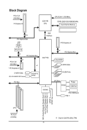
...) 1 PCI Express x16 LGA1156 CPU CPU CLK+/- (133 MHz) DDR3 2200/1333/1066/800 MHz Dual Channel Memory x16 PCI Express Bus LAN RJ45 RTL8111D x1 PCI Express Bus x1 PCIe CLK (100 MHz) x1 1 PCI Express x1 2 SATA 3Gb/s ATA-133/100/66/33 IDE Channel GIGABYTE SATA2 PCI Bus DMI Interface...® P55 x4 PCI Express Bus Dual BIOS 6 SATA 3Gb/s 14 USB Ports CODEC LPC Bus IT8720 Floppy COM Port PS/2 KB/Mouse TPM j MIC (Center/Subwoofer Speaker Out) Line-Out (Front Speaker Out) Line-In (Rear Speaker Out) S/PDIF In S/PDIF Out 4 PCI PCI CLK (33 MHz) j Only for GA-P55-UD3L-TPM...
...) 1 PCI Express x16 LGA1156 CPU CPU CLK+/- (133 MHz) DDR3 2200/1333/1066/800 MHz Dual Channel Memory x16 PCI Express Bus LAN RJ45 RTL8111D x1 PCI Express Bus x1 PCIe CLK (100 MHz) x1 1 PCI Express x1 2 SATA 3Gb/s ATA-133/100/66/33 IDE Channel GIGABYTE SATA2 PCI Bus DMI Interface...® P55 x4 PCI Express Bus Dual BIOS 6 SATA 3Gb/s 14 USB Ports CODEC LPC Bus IT8720 Floppy COM Port PS/2 KB/Mouse TPM j MIC (Center/Subwoofer Speaker Out) Line-Out (Front Speaker Out) Line-In (Rear Speaker Out) S/PDIF In S/PDIF Out 4 PCI PCI CLK (33 MHz) j Only for GA-P55-UD3L-TPM...
Manual
Page 11
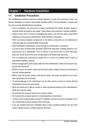
... 1 Hardware Installation 1-1 Installation Precautions The motherboard contains numerous delicate electronic circuits and components which can lead to damage to system components as well as a motherboard, CPU or memory. ponents such as physical harm to the user. • If you are uncertain about any metal leads or connectors. • It is best...
... 1 Hardware Installation 1-1 Installation Precautions The motherboard contains numerous delicate electronic circuits and components which can lead to damage to system components as well as a motherboard, CPU or memory. ponents such as physical harm to the user. • If you are uncertain about any metal leads or connectors. • It is best...
Manual
Page 12
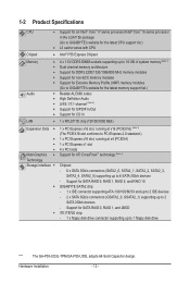
...to 1 floppy disk drive "*" The GA-P55-UD3L-TPM/GA-P55-UD3L adopts All-Solid Capacitor design. Support for SATA RAID 0, RAID 1, RAID 5, and RAID 10 GIGABYTE SATA2 chip: - 1 x IDE ...connector supporting ATA-133/100/66/33 and up to 2 IDE devices - 2 x SATA 3Gb/s connectors (GSATA2_0, GSATA2_1) supporting up to 6 SATA 3Gb/s devices - Hardware Installation - 12 - 1-2 Product Specifications CPU...
...to 1 floppy disk drive "*" The GA-P55-UD3L-TPM/GA-P55-UD3L adopts All-Solid Capacitor design. Support for SATA RAID 0, RAID 1, RAID 5, and RAID 10 GIGABYTE SATA2 chip: - 1 x IDE ...connector supporting ATA-133/100/66/33 and up to 2 IDE devices - 2 x SATA 3Gb/s connectors (GSATA2_0, GSATA2_1) supporting up to 6 SATA 3Gb/s devices - Hardware Installation - 12 - 1-2 Product Specifications CPU...

Manual
Page 13
... internal USB headers) Internal w 1 x 24-pin ATX main power connector Connectors w 1 x 4-pin ATX 12V power connector w 1 x floppy disk drive connector w 1 x IDE connector w 8 x SATA 3Gb/s connectors w 1 x CPU fan header w 2 x system fan headers w 1 x power fan header w 1 x front panel header w 1 x front panel audio header w 1 x CD In connector w 1 x S/PDIF In header w 1 x S/PDIF Out header w 3 x USB...
... internal USB headers) Internal w 1 x 24-pin ATX main power connector Connectors w 1 x 4-pin ATX 12V power connector w 1 x floppy disk drive connector w 1 x IDE connector w 8 x SATA 3Gb/s connectors w 1 x CPU fan header w 2 x system fan headers w 1 x power fan header w 1 x front panel header w 1 x front panel audio header w 1 x CD In connector w 1 x S/PDIF In header w 1 x S/PDIF Out header w 3 x USB...
Manual
Page 14
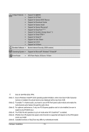
... Operating System w Support for Microsoft® Windows® 7/Vista/XP Form Factor w ATX Form Factor; 30.5cm x 19.0cm j Only for GA-P55-UD3L-TPM. (Note 1) Due to Windows Vista/XP 32-bit operating system limitation, when more than 4 GB of physical memory is installed, the actual ... The PCIEX16 slot operates at up to x4 mode when ATI CrossFireX™ is enabled. (Note 5) Whether the CPU/system fan speed control function is supported will depend on the CPU/system cooler you install. (Note 6) Available functions in EasyTune may differ by motherboard model. Hardware Installation - 14...
... Operating System w Support for Microsoft® Windows® 7/Vista/XP Form Factor w ATX Form Factor; 30.5cm x 19.0cm j Only for GA-P55-UD3L-TPM. (Note 1) Due to Windows Vista/XP 32-bit operating system limitation, when more than 4 GB of physical memory is installed, the actual ... The PCIEX16 slot operates at up to x4 mode when ATI CrossFireX™ is enabled. (Note 5) Whether the CPU/system fan speed control function is supported will depend on the CPU/system cooler you install. (Note 6) Available functions in EasyTune may differ by motherboard model. Hardware Installation - 14...
Manual
Page 15
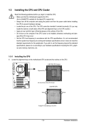
... outlet before you begin to install the CPU: • Make sure that the motherboard supports the CPU. (Go to GIGABYTE's website for the peripherals. Hardware Installation LGA1156 CPU Socket Alignment Key Alignment Key Pin One Corner of the CPU. It is not installed, otherwise overheating and dam- The CPU cannot be set the frequency beyond hardware...
... outlet before you begin to install the CPU: • Make sure that the motherboard supports the CPU. (Go to GIGABYTE's website for the peripherals. Hardware Installation LGA1156 CPU Socket Alignment Key Alignment Key Pin One Corner of the CPU. It is not installed, otherwise overheating and dam- The CPU cannot be set the frequency beyond hardware...
Manual
Page 16
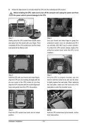
...handle down and away from the power outlet to prevent damage to correctly install the CPU into the motherboard CPU socket. To protect the CPU socket, always replace the protective socket cover when the CPU is properly inserted, use one hand to hold the socket lever and use the ...vertically. (DO NOT touch socket contacts. Hardware Installation - 16 - NOTE: Hold the CPU socket lever by the handle, not the lever base portion. Step 4: Once the CPU is not installed.) Step 3: Hold the CPU with the pin one marking (triangle) with your finger. When replacing the load plate,...
...handle down and away from the power outlet to prevent damage to correctly install the CPU into the motherboard CPU socket. To protect the CPU socket, always replace the protective socket cover when the CPU is properly inserted, use one hand to hold the socket lever and use the ...vertically. (DO NOT touch socket contacts. Hardware Installation - 16 - NOTE: Hold the CPU socket lever by the handle, not the lever base portion. Step 4: Once the CPU is not installed.) Step 3: Hold the CPU with the pin one marking (triangle) with your finger. When replacing the load plate,...
Manual
Page 17
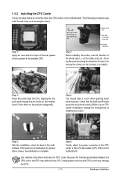
...(The following procedure uses Intel® boxed cooler as the picture above shows, the installation is to install.) Step 3: Place the cooler atop the CPU, aligning the four push pins through the pin holes on the motherboard. If the push pin is inserted as the example cooler.) Step 1: Apply... an even and thin layer of the installed CPU. Inadequately removing the CPU cooler may adhere to the CPU. Push down each push pin. Step 4: You should hear a "click" when pushing down on the surface of thermal ...
...(The following procedure uses Intel® boxed cooler as the picture above shows, the installation is to install.) Step 3: Place the cooler atop the CPU, aligning the four push pins through the pin holes on the motherboard. If the push pin is inserted as the example cooler.) Step 1: Apply... an even and thin layer of the installed CPU. Inadequately removing the CPU cooler may adhere to the CPU. Push down each push pin. Step 4: You should hear a "click" when pushing down on the surface of thermal ...
Manual
Page 18
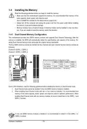
...only one DDR3 memory module is recommended that memory of the same capacity, brand, speed, and chips be used. (Go to GIGABYTE's website for optimum performance. When enabling Dual Channel mode with two or four memory modules, it in the DDR3_1 and DDR3_3 sockets.... This motherboard provides four DDR3 memory sockets and supports Dual Channel Technology. If only one DDR3 memory module is installed, it is recommended to CPU limitations, read the following : Channel 0: DDR3_1, DDR3_2 Channel 1: DDR3_3, DDR3_4 Dual Channel Memory Configurations Table DDR3_2 DDR3_1 DDR3_4 DDR3_3 Two Modules...
...only one DDR3 memory module is recommended that memory of the same capacity, brand, speed, and chips be used. (Go to GIGABYTE's website for optimum performance. When enabling Dual Channel mode with two or four memory modules, it in the DDR3_1 and DDR3_3 sockets.... This motherboard provides four DDR3 memory sockets and supports Dual Channel Technology. If only one DDR3 memory module is installed, it is recommended to CPU limitations, read the following : Channel 0: DDR3_1, DDR3_2 Channel 1: DDR3_3, DDR3_4 Dual Channel Memory Configurations Table DDR3_2 DDR3_1 DDR3_4 DDR3_3 Two Modules...
Manual
Page 24
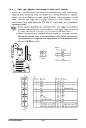
The power connector possesses a foolproof design. Connect the power supply cable to the CPU. When using a 2x10 power supply. 3 4 1 2 ATX_12V ATX_12V: Pin No. 1 2 3 4 Definition GND GND +12V +12V 12 24 1 13 ATX ATX: Pin No. 1 2 3 4 5 6 7 8 9 10 11 12 Definition ...
The power connector possesses a foolproof design. Connect the power supply cable to the CPU. When using a 2x10 power supply. 3 4 1 2 ATX_12V ATX_12V: Pin No. 1 2 3 4 Definition GND GND +12V +12V 12 24 1 13 ATX ATX: Pin No. 1 2 3 4 5 6 7 8 9 10 11 12 Definition ...
Manual
Page 25
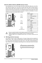
... optional floppy disk drive cable, please contact the local dealer. 33 1 34 2 - 25 - 3/4/5) CPU_FAN/SYS_FAN1/SYS_FAN2/PWR_FAN (Fan Headers) The motherboard has a 4-pin CPU fan header (CPU_FAN), a 4-pin (SYS_FAN2) and a 3-pin (SYS_ FAN1) system fan headers, and a 3-pin power fan header (PWR_FAN). Definition 1 GND 2 +... fan speed control design. The pin 1 of the cable is the ground wire). For optimum heat dissipation, it in damage to prevent your CPU and system from overheating. The types of the connector and the floppy disk drive cable. Definition 1 SYS_FAN2 1 GND 2 +12V / Speed ...
... optional floppy disk drive cable, please contact the local dealer. 33 1 34 2 - 25 - 3/4/5) CPU_FAN/SYS_FAN1/SYS_FAN2/PWR_FAN (Fan Headers) The motherboard has a 4-pin CPU fan header (CPU_FAN), a 4-pin (SYS_FAN2) and a 3-pin (SYS_ FAN1) system fan headers, and a 3-pin power fan header (PWR_FAN). Definition 1 GND 2 +... fan speed control design. The pin 1 of the cable is the ground wire). For optimum heat dissipation, it in damage to prevent your CPU and system from overheating. The types of the connector and the floppy disk drive cable. Definition 1 SYS_FAN2 1 GND 2 +12V / Speed ...
Manual
Page 32
Hardware Installation - 32 - Refer to Chapter 4, "Dynamic Energy Saver™ 2," for more the number of lighted LEDs indicates the CPU loading. The higher the CPU loading, the more details. 18) PHASE LED The number of lighted LEDs. To enable the Phase LED display function, please first enable Dynamic Energy Saver™ 2.
Hardware Installation - 32 - Refer to Chapter 4, "Dynamic Energy Saver™ 2," for more the number of lighted LEDs indicates the CPU loading. The higher the CPU loading, the more details. 18) PHASE LED The number of lighted LEDs. To enable the Phase LED display function, please first enable Dynamic Energy Saver™ 2.
Manual
Page 35
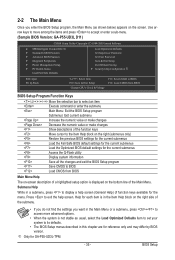
...for the menu. BIOS Setup Use arrow keys to move among the items and press to accept or enter a sub-menu. (Sample BIOS Version: GA-P55-UD3L D11) CMOS Setup Utility-Copyright (C) 1984-2009 Award Software MB Intelligent Tweaker(M.I.T.) Standard CMOS Features Advanced BIOS Features ... & Exit Setup Exit Without Saving Security Chip Configuration j ESC: Quit F8: Q-Flash Select Item F10: Save & Exit Setup Change CPU's Clock & Voltage F11: Save CMOS to BIOS F12: Load CMOS from BIOS Main Menu Help The on-screen description of a highlighted setup option...
...for the menu. BIOS Setup Use arrow keys to move among the items and press to accept or enter a sub-menu. (Sample BIOS Version: GA-P55-UD3L D11) CMOS Setup Utility-Copyright (C) 1984-2009 Award Software MB Intelligent Tweaker(M.I.T.) Standard CMOS Features Advanced BIOS Features ... & Exit Setup Exit Without Saving Security Chip Configuration j ESC: Quit F8: Q-Flash Select Item F10: Save & Exit Setup Change CPU's Clock & Voltage F11: Save CMOS to BIOS F12: Load CMOS from BIOS Main Menu Help The on-screen description of a highlighted setup option...
Manual
Page 36
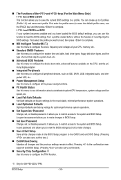
...the system boot, etc. Advanced BIOS Features Use this menu to configure the device boot order, advanced features available on the CPU, and the primary display adapter. Integrated Peripherals Use this menu to configure all peripheral devices, such as IDE, SATA, ... about autodetected system/CPU temperature, system voltage and fan speed, etc. Load Fail-Safe Defaults Fail-Safe defaults are factory settings for the most stable, minimal-performance system operations. Load Optimized Defaults Optimized defaults are factory settings for GA-P55-UD3L-TPM. A user...
...the system boot, etc. Advanced BIOS Features Use this menu to configure the device boot order, advanced features available on the CPU, and the primary display adapter. Integrated Peripherals Use this menu to configure all peripheral devices, such as IDE, SATA, ... about autodetected system/CPU temperature, system voltage and fan speed, etc. Load Fail-Safe Defaults Fail-Safe defaults are factory settings for the most stable, minimal-performance system operations. Load Optimized Defaults Optimized defaults are factory settings for GA-P55-UD3L-TPM. A user...
Manual
Page 37
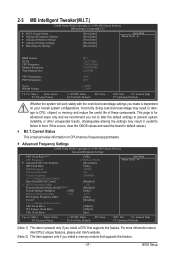
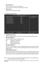
...the default settings to prevent system instability or other unexpected results. (Inadequately altering the settings may result in system's failure to CPU, chipset, or memory and reduce the useful life of these components. If this feature. - 37 - 2-3 MB Intelligent ... Advanced Frequency Settings CMOS Setup Utility-Copyright (C) 1984-2009 Award Software Advanced Frequency Settings CPU Clock Ratio (Note 1) CPU Frequency } Advanced CPU Core Features QPI Clock Ratio QPI Link Speed Uncore Clock Ratio Uncore Frequency >>>>> Standard Clock Control Base...
...the default settings to prevent system instability or other unexpected results. (Inadequately altering the settings may result in system's failure to CPU, chipset, or memory and reduce the useful life of these components. If this feature. - 37 - 2-3 MB Intelligent ... Advanced Frequency Settings CMOS Setup Utility-Copyright (C) 1984-2009 Award Software Advanced Frequency Settings CPU Clock Ratio (Note 1) CPU Frequency } Advanced CPU Core Features QPI Clock Ratio QPI Link Speed Uncore Clock Ratio Uncore Frequency >>>>> Standard Clock Control Base...
Manual
Page 38
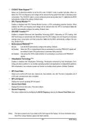
... to enable multi-threading technology when using an Intel CPU that support multi-processor mode. (Default: Enabled) CPU Enhanced Halt (C1E) (Note) Enables or disables Intel CPU Enhanced Halt (C1E) function, a CPU power-saving function in system halt state. CPU Cores Enabled (Note) CPU Multi-Threading (Note) CPU Enhanced Halt (C1E) (Note) C3/C6/C7 State Support...
... to enable multi-threading technology when using an Intel CPU that support multi-processor mode. (Default: Enabled) CPU Enhanced Halt (C1E) (Note) Enables or disables Intel CPU Enhanced Halt (C1E) function, a CPU power-saving function in system halt state. CPU Cores Enabled (Note) CPU Multi-Threading (Note) CPU Enhanced Halt (C1E) (Note) C3/C6/C7 State Support...
Manual
Page 39
.... (Default: Auto) Bi-Directional PROCHOT (Note) Auto Lets the BIOS automatically configure this setting. (Default) Enabled When the CPU or chipset detects that supports this feature. The C3/C6/C7 state is installed. Auto lets the BIOS automatically configure this setting. (...Default: Auto) CPU Thermal Monitor (Note) Enables or disables Intel CPU Thermal Monitor function, a CPU overheating protection function. Virtualization enhanced by the Uncore Clock Ratio value. (Note) This item is present...
.... (Default: Auto) Bi-Directional PROCHOT (Note) Auto Lets the BIOS automatically configure this setting. (Default) Enabled When the CPU or chipset detects that supports this feature. The C3/C6/C7 state is installed. Auto lets the BIOS automatically configure this setting. (...Default: Auto) CPU Thermal Monitor (Note) Enables or disables Intel CPU Thermal Monitor function, a CPU overheating protection function. Virtualization enhanced by the Uncore Clock Ratio value. (Note) This item is present...
Manual
Page 40
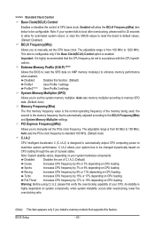
... option is automatically adjusted according to the BCLK Frequency(Mhz) and System Memory Multiplier settings. Important: It is designed to automatically adjust CPU computing power to manually set the PCIe clock frequency. BIOS Setup - 40 - System Memory Multiplier (SPD) Allows you to maximize ... memory multiplier according to memory SPD data. (Default: Auto) Memory Frequency(Mhz) The first memory frequency value is highly dependent on CPU loading. Note: If your system fails to boot after overclocking, lower the overclocking ratio. (Note) This item appears only if you...
... option is automatically adjusted according to the BCLK Frequency(Mhz) and System Memory Multiplier settings. Important: It is designed to automatically adjust CPU computing power to manually set the PCIe clock frequency. BIOS Setup - 40 - System Memory Multiplier (SPD) Allows you to maximize ... memory multiplier according to memory SPD data. (Default: Auto) Memory Frequency(Mhz) The first memory frequency value is highly dependent on CPU loading. Note: If your system fails to boot after overclocking, lower the overclocking ratio. (Note) This item appears only if you...
Manual
Page 41
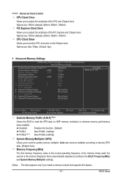
...first memory frequency value is the normal operating frequency of the memory being used; Auto sets memory multiplier according to set the CPU clock prior to adjust the amplitude of the PCI Express and Chipset clock. BIOS Setup PCI Express Clock Drive Allows you to ...Memory Multiplier settings. (Note) This item appears only if you install a memory module that is automatically adjusted according to adjust the amplitude of the CPU and Chipset clock. Disabled Disables this feature. - 41 - the second is the memory frequency that supports this function. (Default) Profile1 Uses Profile...
...first memory frequency value is the normal operating frequency of the memory being used; Auto sets memory multiplier according to set the CPU clock prior to adjust the amplitude of the PCI Express and Chipset clock. BIOS Setup PCI Express Clock Drive Allows you to ...Memory Multiplier settings. (Note) This item appears only if you install a memory module that is automatically adjusted according to adjust the amplitude of the CPU and Chipset clock. Disabled Disables this feature. - 41 - the second is the memory frequency that supports this function. (Default) Profile1 Uses Profile...


