Manual
Page 3
... Support&Downloads\Motherboard\Technology Guide page on your motherboard revision before updating motherboard BIOS, drivers, or when looking for technical information. Check your motherboard looks like this manual may be reproduced, copied, translated, transmitted, or published in this product, GIGABYTE provides the following types of documentations: For quick set-up of the...
... Support&Downloads\Motherboard\Technology Guide page on your motherboard revision before updating motherboard BIOS, drivers, or when looking for technical information. Check your motherboard looks like this manual may be reproduced, copied, translated, transmitted, or published in this product, GIGABYTE provides the following types of documentations: For quick set-up of the...
Manual
Page 4
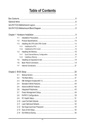
Table of Contents Box Contents...6 Optional Items...6 GA-P41T-D3 Motherboard Layout 7 GA-P41T-D3 Motherboard Block Diagram 8 Chapter 1 Hardware Installation 9 1-1 Installation Precautions 9 1-2 Product Specifications 10 1-3 Installing the CPU and CPU ... an Expansion Card 18 1-6 Back Panel Connectors 19 1-7 Internal Connectors 21 Chapter 2 BIOS Setup 29 2-1 Startup Screen 30 2-2 The Main Menu 31 2-3 MB Intelligent Tweaker(M.I.T 33 2-4 Standard CMOS Features 40 2-5 Advanced BIOS Features 42 2-6 Integrated Peripherals 45 2-7 Power Management Setup 48 2-8 PnP/PCI Configurations ...
Table of Contents Box Contents...6 Optional Items...6 GA-P41T-D3 Motherboard Layout 7 GA-P41T-D3 Motherboard Block Diagram 8 Chapter 1 Hardware Installation 9 1-1 Installation Precautions 9 1-2 Product Specifications 10 1-3 Installing the CPU and CPU ... an Expansion Card 18 1-6 Back Panel Connectors 19 1-7 Internal Connectors 21 Chapter 2 BIOS Setup 29 2-1 Startup Screen 30 2-2 The Main Menu 31 2-3 MB Intelligent Tweaker(M.I.T 33 2-4 Standard CMOS Features 40 2-5 Advanced BIOS Features 42 2-6 Integrated Peripherals 45 2-7 Power Management Setup 48 2-8 PnP/PCI Configurations ...
Manual
Page 5
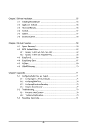
... 56 3-3 Technical Manuals 56 3-4 Contact...57 3-5 System...57 3-6 Download Center 58 Chapter 4 Unique Features 59 4-1 Xpress Recovery2 59 4-2 BIOS Update Utilities 62 4-2-1 Updating the BIOS with the Q-Flash Utility 62 4-2-2 Updating the BIOS with the @BIOS Utility 65 4-3 EasyTune 6...66 4-4 Easy Energy Saver 67 4-5 Q-Share...69 4-6 SMART Recovery 70 Chapter 5 Appendix...71 5-1 Configuring Audio...
... 56 3-3 Technical Manuals 56 3-4 Contact...57 3-5 System...57 3-6 Download Center 58 Chapter 4 Unique Features 59 4-1 Xpress Recovery2 59 4-2 BIOS Update Utilities 62 4-2-1 Updating the BIOS with the Q-Flash Utility 62 4-2-2 Updating the BIOS with the @BIOS Utility 65 4-3 EasyTune 6...66 4-4 Easy Energy Saver 67 4-5 Q-Share...69 4-6 SMART Recovery 70 Chapter 5 Appendix...71 5-1 Configuring Audio...
Manual
Page 8
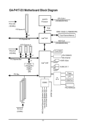
GA-P41T-D3 Motherboard Block Diagram PCIe CLK (100 MHz) 1 PCI Express x16 x16 PCI Express x16 3 PCI Express x1 PCIe CLK (100 MHz) x1 x1 x1 PCI ... MHz) Host Interface Intel® G41 DDR3 1333(O.C.)/1066/800 MHz Dual Channel Memory MCH CLK (333/266/200 MHz) Intel® ICH7 CODEC Dual BIOS ATA-100/66/33 IDE Channel 4 SATA 3Gb/s 8 USB 2.0/1.1 iTE IT8718 Floppy LPT COM Port PS/2 KB/Mouse MIC (Center/Subwoofer Speaker Out) Line-Out...
GA-P41T-D3 Motherboard Block Diagram PCIe CLK (100 MHz) 1 PCI Express x16 x16 PCI Express x16 3 PCI Express x1 PCIe CLK (100 MHz) x1 x1 x1 PCI ... MHz) Host Interface Intel® G41 DDR3 1333(O.C.)/1066/800 MHz Dual Channel Memory MCH CLK (333/266/200 MHz) Intel® ICH7 CODEC Dual BIOS ATA-100/66/33 IDE Channel 4 SATA 3Gb/s 8 USB 2.0/1.1 iTE IT8718 Floppy LPT COM Port PS/2 KB/Mouse MIC (Center/Subwoofer Speaker Out) Line-Out...
Manual
Page 11
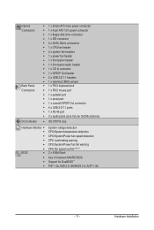
... port w 1 x serial port w 1 x coaxial S/PDIF Out connector w 4 x USB 2.0/1.1 ports w 1 x RJ-45 port w 3 x audio jacks (Line In/Line Out/Microphone) I/O Controller w iTE IT8718 chip Hardware Monitor w w w w w w BIOS w w w w System voltage detection CPU/System temperature detection CPU/System/Power fan speed detection CPU overheating warning CPU/System/Power fan fail warning CPU fan speed...
... port w 1 x serial port w 1 x coaxial S/PDIF Out connector w 4 x USB 2.0/1.1 ports w 1 x RJ-45 port w 3 x audio jacks (Line In/Line Out/Microphone) I/O Controller w iTE IT8718 chip Hardware Monitor w w w w w w BIOS w w w w System voltage detection CPU/System temperature detection CPU/System/Power fan speed detection CPU overheating warning CPU/System/Power fan fail warning CPU fan speed...
Manual
Page 12
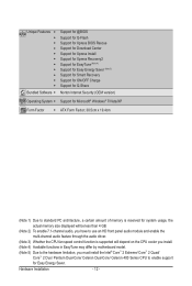
Unique Features w w w w w w w w w w w Bundled Software w Support for @BIOS Support for Q-Flash Support for Xpress BIOS Rescue Support for Download Center Support for Xpress Install Support for Xpress Recovery2 Support for EasyTune (Note 4) Support for Easy Energy Saver (Note 5) Support for ...
Unique Features w w w w w w w w w w w Bundled Software w Support for @BIOS Support for Q-Flash Support for Xpress BIOS Rescue Support for Download Center Support for Xpress Install Support for Xpress Recovery2 Support for EasyTune (Note 4) Support for Easy Energy Saver (Note 5) Support for ...
Manual
Page 16
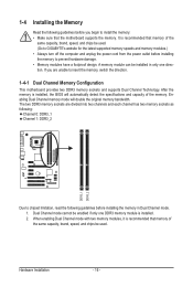
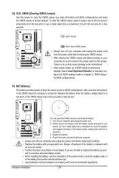
...and supports Dual Channel Technology. It is installed. 2. When enabling Dual Channel mode with two memory modules, it is installed, the BIOS will double the original memory bandwidth. A memory module can be used . Enabling Dual Channel memory mode will automatically detect the specifications and... capacity of the same capacity, brand, speed, and chips be used . (Go to GIGABYTE's website for the latest supported memory speeds and memory modules.) • Always turn off the computer and unplug the power cord from ...
...and supports Dual Channel Technology. It is installed. 2. When enabling Dual Channel mode with two memory modules, it is installed, the BIOS will double the original memory bandwidth. A memory module can be used . Enabling Dual Channel memory mode will automatically detect the specifications and... capacity of the same capacity, brand, speed, and chips be used . (Go to GIGABYTE's website for the latest supported memory speeds and memory modules.) • Always turn off the computer and unplug the power cord from ...
Manual
Page 18
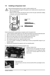
...slot. 1. 1-5 Installing an Expansion Card Read the following guidelines before installing an expansion card to prevent hardware damage. If necessary, go to BIOS Setup to correctly install your expansion card in your expansion card(s). 7. Locate an expansion slot that came with the slot, and press down...slot. 3. Hardware Installation - 18 - PCI Express x1 Slot PCI Express x16 Slot PCI Slot Follow the steps below to make any required BIOS changes for your operating system. Install the driver provided with a screw. 5. Make sure the metal contacts on the top edge of the ...
...slot. 1. 1-5 Installing an Expansion Card Read the following guidelines before installing an expansion card to prevent hardware damage. If necessary, go to BIOS Setup to correctly install your expansion card in your expansion card(s). 7. Locate an expansion slot that came with the slot, and press down...slot. 3. Hardware Installation - 18 - PCI Express x1 Slot PCI Express x16 Slot PCI Slot Follow the steps below to make any required BIOS changes for your operating system. Install the driver provided with a screw. 5. Make sure the metal contacts on the top edge of the ...

Manual
Page 25
PWR- When connecting your system using the power switch (refer to Chapter 2, "BIOS Setup," "Power Management Setup," for information about beep codes. • HD (Hard Drive Activity LED) Connects to the hard drive activity LED on the chassis ... power switch, reset switch, power LED, hard drive activity LED, speaker and etc. The LED S0 On is on when the system is detected, the BIOS may differ by issuing a beep code. If a problem is operating. Refer to Chapter 5, "Troubleshooting," for more information). • SPEAK (Speaker): Connects to the speaker on...
PWR- When connecting your system using the power switch (refer to Chapter 2, "BIOS Setup," "Power Management Setup," for information about beep codes. • HD (Hard Drive Activity LED) Connects to the hard drive activity LED on the chassis ... power switch, reset switch, power LED, hard drive activity LED, speaker and etc. The LED S0 On is on when the system is detected, the BIOS may differ by issuing a beep code. If a problem is operating. Refer to Chapter 5, "Troubleshooting," for more information). • SPEAK (Speaker): Connects to the speaker on...
Manual
Page 28
... (Or use a metal object like a screwdriver to touch the two pins for one . Danger of the battery holder, making them short for BIOS configurations). 15) BAT (Battery) The battery provides power to factory defaults. Failure to do so may cause damage to the motherboard. • ...battery when the battery voltage drops to clear the CMOS values (e.g. Replace the battery. 4. date information and BIOS configurations) and reset the CMOS values to keep the values (such as BIOS configurations, date, and time information) in accordance with an incorrect model. • Contact the place of...
... (Or use a metal object like a screwdriver to touch the two pins for one . Danger of the battery holder, making them short for BIOS configurations). 15) BAT (Battery) The battery provides power to factory defaults. Failure to do so may cause damage to the motherboard. • ...battery when the battery voltage drops to clear the CMOS values (e.g. Replace the battery. 4. date information and BIOS configurations) and reset the CMOS values to keep the values (such as BIOS configurations, date, and time information) in accordance with an incorrect model. • Contact the place of...
Manual
Page 29
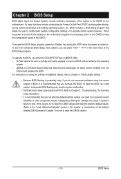
... turned off, the battery on using the current version of BIOS, it with caution. To upgrade the BIOS, use either the GIGABYTE Q-Flash or @BIOS utility. • Q-Flash allows the user to quickly and easily upgrade or back up BIOS without entering the operating system. • @BIOS is a Windows-based utility that searches and downloads the...
... turned off, the battery on using the current version of BIOS, it with caution. To upgrade the BIOS, use either the GIGABYTE Q-Flash or @BIOS utility. • Q-Flash allows the user to quickly and easily upgrade or back up BIOS without entering the operating system. • @BIOS is a Windows-based utility that searches and downloads the...
Manual
Page 30
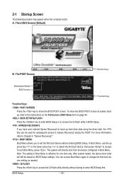
..., Award Software, Inc. Note: The setting in Boot Menu. The system will still be used for one time only. BIOS Setup - 30 - Motherboard Model BIOS Version P41T-D3 E1 . . . . : BIOS Setup : XpressRecovery2 : Boot Menu : Qflash 05/06/2010-G41-ICH7-6A79PG09C-00 Function Keys Function Keys Function Keys: :...the device configured in Boot Menu is effective for subsequent access to show the BIOS POST screen at system startup, refer to the instructions on the Full Screen LOGO Show item on BIOS Setup settings. 2-1 Startup Screen The following screens may appear when the computer...
..., Award Software, Inc. Note: The setting in Boot Menu. The system will still be used for one time only. BIOS Setup - 30 - Motherboard Model BIOS Version P41T-D3 E1 . . . . : BIOS Setup : XpressRecovery2 : Boot Menu : Qflash 05/06/2010-G41-ICH7-6A79PG09C-00 Function Keys Function Keys Function Keys: :...the device configured in Boot Menu is effective for subsequent access to show the BIOS POST screen at system startup, refer to the instructions on the Full Screen LOGO Show item on BIOS Setup settings. 2-1 Startup Screen The following screens may appear when the computer...

Manual
Page 31
...Without Saving ESC: Quit F8: Q-Flash Select Item F10: Save & Exit Setup Change CPU's Clock & Voltage F11: Save CMOS to BIOS F12: Load CMOS from BIOS BIOS Setup Program Function Keys Move the selection bar to select an item Execute command or enter the submenu Main Menu: Exit the... settings for the current submenus Access the Q-Flash utility Display system information Save all the changes and exit the BIOS Setup program Save CMOS to its defaults. • The BIOS Setup menus described in the Main Menu or a submenu, press + to access more advanced options. • ...
...Without Saving ESC: Quit F8: Q-Flash Select Item F10: Save & Exit Setup Change CPU's Clock & Voltage F11: Save CMOS to BIOS F12: Load CMOS from BIOS BIOS Setup Program Function Keys Move the selection bar to select an item Execute command or enter the submenu Main Menu: Exit the... settings for the current submenus Access the Q-Flash utility Display system information Save all the changes and exit the BIOS Setup program Save CMOS to its defaults. • The BIOS Setup menus described in the Main Menu or a submenu, press + to access more advanced options. • ...

Manual
Page 32
...time and date, hard drive types, floppy disk drive types, and the type of errors that stop the system boot, etc. Advanced BIOS Features Use this menu to configure the device boot order, advanced features available on the CPU, and the primary display adapter. Integrated ... 1-8) and name each profile. First select the profile you wish to load, then press to complete. MB Intelligent Tweaker(M.I.T.) Use this task.) BIOS Setup - 32 - It allows you can also carry out this menu to configure the clock, frequency and voltages of your system becomes unstable and you...
...time and date, hard drive types, floppy disk drive types, and the type of errors that stop the system boot, etc. Advanced BIOS Features Use this menu to configure the device boot order, advanced features available on the CPU, and the primary display adapter. Integrated ... 1-8) and name each profile. First select the profile you wish to load, then press to complete. MB Intelligent Tweaker(M.I.T.) Use this task.) BIOS Setup - 32 - It allows you can also carry out this menu to configure the clock, frequency and voltages of your system becomes unstable and you...

Manual
Page 33
... configurations. If this occurs, clear the CMOS values and reset the board to CPU, chipset, or memory and reduce the useful life of these components. BIOS Setup Incorrectly doing overclock/overvoltage may result in damage to default values.) (Note) This item appears only if you install a CPU that supports this feature...
... configurations. If this occurs, clear the CMOS values and reset the board to CPU, chipset, or memory and reduce the useful life of these components. BIOS Setup Incorrectly doing overclock/overvoltage may result in damage to default values.) (Note) This item appears only if you install a CPU that supports this feature...

Manual
Page 34
... feature. mode based on system configurations. Fine CPU Clock Ratio (Note) Allows you install a CPU that the CPU frequency be configurable. Auto allows the BIOS to manually set in accordance with unlocked clock ratio is from 100 MHz to 150 MHz. This item is configurable only if the CPU Host... Clock Control option is installed. BIOS Setup - 34 - Options are: Auto (default), Fast, Turbo. CPU Clock Ratio (Note) Allows you to enhance the performance of CPU host clock. The item...
... feature. mode based on system configurations. Fine CPU Clock Ratio (Note) Allows you install a CPU that the CPU frequency be configurable. Auto allows the BIOS to manually set in accordance with unlocked clock ratio is from 100 MHz to 150 MHz. This item is configurable only if the CPU Host... Clock Control option is installed. BIOS Setup - 34 - Options are: Auto (default), Fast, Turbo. CPU Clock Ratio (Note) Allows you to enhance the performance of CPU host clock. The item...

Manual
Page 35
... Multiplier settings. tRAS Options are dependent on CPU FSB and the (G)MCH Frequency Latch settings. Extreme Lets the system operate at its good performance level. BIOS Setup
... Multiplier settings. tRAS Options are dependent on CPU FSB and the (G)MCH Frequency Latch settings. Extreme Lets the system operate at its good performance level. BIOS Setup

Manual
Page 36
... : Auto (default), 1~15. tRTP Options are : Auto (default), 1~31. Command Rate(CMD) Options are : Auto (default), 1~31. ESC: Exit F1: General Help F7: Optimized Defaults BIOS Setup - 36 - tWTR Options are : Auto (default), 1~3.
... : Auto (default), 1~15. tRTP Options are : Auto (default), 1~31. Command Rate(CMD) Options are : Auto (default), 1~31. ESC: Exit F1: General Help F7: Optimized Defaults BIOS Setup - 36 - tWTR Options are : Auto (default), 1~3.

Manual
Page 37
... Adjustment Options are : Auto (default), 1~15. Twr2wr(Different Rank) Options are : Auto (default), 0-Normal, 1-Advanced. DIMM1 Clock Skew Control Options are : Auto (default), 0-Normal, 1-Advanced. BIOS Setup tRD Phase2 Adjustment Options are : Auto (default), +800ps~-700ps. Trd2rd(Different Rank) Options are : Auto (default), 1~15. Trd2wr(Same/Diff Rank) Options are : Auto...
... Adjustment Options are : Auto (default), 1~15. Twr2wr(Different Rank) Options are : Auto (default), 0-Normal, 1-Advanced. DIMM1 Clock Skew Control Options are : Auto (default), 0-Normal, 1-Advanced. BIOS Setup tRD Phase2 Adjustment Options are : Auto (default), +800ps~-700ps. Trd2rd(Different Rank) Options are : Auto (default), 1~15. Trd2wr(Same/Diff Rank) Options are : Auto...

Manual
Page 38
...Save F6: Fail-Safe Defaults Driving Strength Profile Options are : Auto (default), +8~-7. ESC: Exit F1: General Help F7: Optimized Defaults BIOS Setup - 38 - Data Driving Pull-Up Level Options are : Auto (default). Data Driving Pull-Down Level Options are : Auto (default), +8~-7. Auto... Lets the BIOS decide whether to enhance memory compatibility. Ctrl Driving Pull-Up Level Options are : Auto (default), +8~-7. Cmd Driving Pull-Up Level Options are ...
...Save F6: Fail-Safe Defaults Driving Strength Profile Options are : Auto (default), +8~-7. ESC: Exit F1: General Help F7: Optimized Defaults BIOS Setup - 38 - Data Driving Pull-Up Level Options are : Auto (default). Data Driving Pull-Down Level Options are : Auto (default), +8~-7. Auto... Lets the BIOS decide whether to enhance memory compatibility. Ctrl Driving Pull-Up Level Options are : Auto (default), +8~-7. Cmd Driving Pull-Up Level Options are ...


