Manual
Page 1
GA-P35-S3G LGA775 socket motherboard for Intel® CoreTM processor family/ Intel® Pentium® processor family/Intel® Celeron® processor family User's Manual Rev. 1002 12ME-P35S3G-1002R
GA-P35-S3G LGA775 socket motherboard for Intel® CoreTM processor family/ Intel® Pentium® processor family/Intel® Celeron® processor family User's Manual Rev. 1002 12ME-P35S3G-1002R
Manual
Page 2
Motherboard GA-P35-S3G Nov. 14, 2007 Motherboard GA-P35-S3G Nov. 14, 2007
Motherboard GA-P35-S3G Nov. 14, 2007 Motherboard GA-P35-S3G Nov. 14, 2007

Manual
Page 3
... this manual is designated by GIGA-BYTE TECHNOLOGY CO., LTD as the exclu- Changes to use GIGABYTE's unique features, read or download the information on/from the Support\Motherboard\Technology Guide page on your motherboard revision before updating motherboard BIOS, drivers, or when looking for technical information. All rights reserved. is protected by GIGA...
... this manual is designated by GIGA-BYTE TECHNOLOGY CO., LTD as the exclu- Changes to use GIGABYTE's unique features, read or download the information on/from the Support\Motherboard\Technology Guide page on your motherboard revision before updating motherboard BIOS, drivers, or when looking for technical information. All rights reserved. is protected by GIGA...
Manual
Page 4
Table of Contents Box Contents ...6 OptionalItems ...6 GA-P35-S3G Motherboard Layout 7 Block Diagram ...8 Chapter 1 Hardware Installation 9 1-1 Installation Precautions 9 1-2 Product Specifications 10 1-3 Installing the CPU and CPU Cooler 13 1-3-1 Installing the CPU 13 1-3-2 Installing the CPU ...
Table of Contents Box Contents ...6 OptionalItems ...6 GA-P35-S3G Motherboard Layout 7 Block Diagram ...8 Chapter 1 Hardware Installation 9 1-1 Installation Precautions 9 1-2 Product Specifications 10 1-3 Installing the CPU and CPU Cooler 13 1-3-1 Installing the CPU 13 1-3-2 Installing the CPU ...
Manual
Page 6
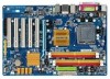
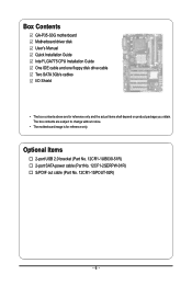
Box Contents GA-P35-S3G motherboard Motherboard driver disk User's Manual Quick Installation Guide Intel® LGA775 CPU Installation Guide One IDE cable and one floppy disk drive cable Two SATA 3Gb/s cables I/O Shield • The box contents above are subject to change without notice. • The motherboard image is for reference only and the actual items...
Box Contents GA-P35-S3G motherboard Motherboard driver disk User's Manual Quick Installation Guide Intel® LGA775 CPU Installation Guide One IDE cable and one floppy disk drive cable Two SATA 3Gb/s cables I/O Shield • The box contents above are subject to change without notice. • The motherboard image is for reference only and the actual items...
Manual
Page 7
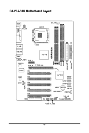
GA-P35-S3G Motherboard Layout KB_MS ATX_12V LGA775 CPU_FAN COMA LPT R_USB USB_LAN AUDIO F_AUDIO RTL8111B PCIE_1 PCIE_16 IT8718 PCI1 CODEC PCI2 CD_IN PCI3 SPDIF_O PCI4 PCI5 FDD IDE ATX GA-P35-S3G DDRII1 DDRII2 DDRII3 DDRII4 JMicron 368 PWR_FAN Intel® P35 SYS_FAN1 Intel® ICH9 SATAII0 SATAII1 SATAII4 MBIOS BATTERY SATAII5 CLR_CMOS SYS_FAN2 PWR_LED F_USB1 CI F_PANEL F_USB3 F_USB2 - 7 -
GA-P35-S3G Motherboard Layout KB_MS ATX_12V LGA775 CPU_FAN COMA LPT R_USB USB_LAN AUDIO F_AUDIO RTL8111B PCIE_1 PCIE_16 IT8718 PCI1 CODEC PCI2 CD_IN PCI3 SPDIF_O PCI4 PCI5 FDD IDE ATX GA-P35-S3G DDRII1 DDRII2 DDRII3 DDRII4 JMicron 368 PWR_FAN Intel® P35 SYS_FAN1 Intel® ICH9 SATAII0 SATAII1 SATAII4 MBIOS BATTERY SATAII5 CLR_CMOS SYS_FAN2 PWR_LED F_USB1 CI F_PANEL F_USB3 F_USB2 - 7 -

Manual
Page 9
...sure the power supply has been turned off. • Before turning on the computer power during the installation process can become damaged as a motherboard, CPU or memory. These stickers are required for warranty validation. • Always remove the AC power by your hands dry and first touch... a metal object to eliminate static electricity. • Prior to installing the motherboard, please have an ESD wrist strap, keep your dealer. Hardware Installation If you are connected tightly and securely. • When handling the...
...sure the power supply has been turned off. • Before turning on the computer power during the installation process can become damaged as a motherboard, CPU or memory. These stickers are required for warranty validation. • Always remove the AC power by your hands dry and first touch... a metal object to eliminate static electricity. • Prior to installing the motherboard, please have an ESD wrist strap, keep your dealer. Hardware Installation If you are connected tightly and securely. • When handling the...
Manual
Page 10
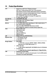
...Edition/Intel® Pentium® 4 processor/ Intel® Celeron® processor in the LGA 775 package (Go to GIGABYTE's website for the latest CPU support list.) Š L2 cache varies with CPU Š 1333/1066/800 MHz FSB Š...memory (Note 1) Š Dual channel memory architecture Š Support for DDR2 1066/800/667 MHz memory modules (Go to GIGABYTE's website for the latest memory support list.) Š Realtek AL662 codec Š High Definition Audio Š 2/4/5.1-channel Š...the back panel, 6 via the USB brackets connected to the internal USB headers) GA-P35-S3G Motherboard - 10 -
...Edition/Intel® Pentium® 4 processor/ Intel® Celeron® processor in the LGA 775 package (Go to GIGABYTE's website for the latest CPU support list.) Š L2 cache varies with CPU Š 1333/1066/800 MHz FSB Š...memory (Note 1) Š Dual channel memory architecture Š Support for DDR2 1066/800/667 MHz memory modules (Go to GIGABYTE's website for the latest memory support list.) Š Realtek AL662 codec Š High Definition Audio Š 2/4/5.1-channel Š...the back panel, 6 via the USB brackets connected to the internal USB headers) GA-P35-S3G Motherboard - 10 -
Manual
Page 12
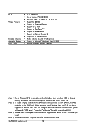
... 3) Whether the CPU fan speed control function is supported will depend on the CPU cooler you install. (Note 4) Available functions in Easytune may differ by motherboard model. GA-P35-S3G Motherboard - 12 -
... 3) Whether the CPU fan speed control function is supported will depend on the CPU cooler you install. (Note 4) Available functions in Easytune may differ by motherboard model. GA-P35-S3G Motherboard - 12 -
Manual
Page 13
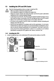
... Pin One Marking on the CPU - 13 - Locate the alignment keys on the motherboard CPU socket and the notches on the computer if the CPU cooler is not recom- mended that the motherboard supports the CPU. (Go to GIGABYTE's website for the peripherals. LGA775 CPU Socket Alignment Key LGA 775 CPU Alignment Key...
... Pin One Marking on the CPU - 13 - Locate the alignment keys on the motherboard CPU socket and the notches on the computer if the CPU cooler is not recom- mended that the motherboard supports the CPU. (Go to GIGABYTE's website for the peripherals. LGA775 CPU Socket Alignment Key LGA 775 CPU Alignment Key...
Manual
Page 14
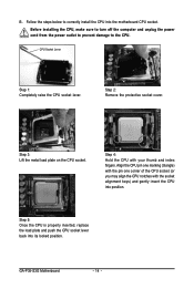
Step 5: Once the CPU is properly inserted, replace the load plate and push the CPU socket lever back into the motherboard CPU socket. GA-P35-S3G Motherboard - 14 - Step 3: Lift the metal load plate on the CPU socket. Before installing the CPU, make sure to turn off the computer and unplug the ...
Step 5: Once the CPU is properly inserted, replace the load plate and push the CPU socket lever back into the motherboard CPU socket. GA-P35-S3G Motherboard - 14 - Step 3: Lift the metal load plate on the CPU socket. Before installing the CPU, make sure to turn off the computer and unplug the ...

Manual
Page 15
1-3-2 Installing the CPU Cooler Follow the steps below to correctly install the CPU cooler on the motherboard. (The following procedure uses Intel® boxed cooler as the picture above, the installation is to install.) Step 3: Place the cooler atop the CPU, aligning ...the four push pins through the pin holes on the motherboard. Use extreme care when removing the CPU cooler because the thermal grease/tape between the CPU cooler and CPU may damage the CPU. - 15 - Inadequately...
1-3-2 Installing the CPU Cooler Follow the steps below to correctly install the CPU cooler on the motherboard. (The following procedure uses Intel® boxed cooler as the picture above, the installation is to install.) Step 3: Place the cooler atop the CPU, aligning ...the four push pins through the pin holes on the motherboard. Use extreme care when removing the CPU cooler because the thermal grease/tape between the CPU cooler and CPU may damage the CPU. - 15 - Inadequately...
Manual
Page 16
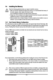
...insert the memory, switch the direction. 1-4-1 Dual Channel Memory Configuration This motherboard provides four DDR2 memory sockets and supports Dual Channel Technology. DS/SS - - GA-P35-S3G Motherboard - 16 - When enabling Dual Channel mode with two or four ...memory modules, it is installed. 2. After the memory is recommended that the motherboard supports the memory. DS/SS DS/SS (SS=Single-Sided, DS=Double-Sided, "- -"=No Memory) DDRII1 DDRII2 DDRII3 DDRII4 Due to be used . (Go to GIGABYTE...
...insert the memory, switch the direction. 1-4-1 Dual Channel Memory Configuration This motherboard provides four DDR2 memory sockets and supports Dual Channel Technology. DS/SS - - GA-P35-S3G Motherboard - 16 - When enabling Dual Channel mode with two or four ...memory modules, it is installed. 2. After the memory is recommended that the motherboard supports the memory. DS/SS DS/SS (SS=Single-Sided, DS=Double-Sided, "- -"=No Memory) DDRII1 DDRII2 DDRII3 DDRII4 Due to be used . (Go to GIGABYTE...

Manual
Page 17
... , make sure to turn off the computer and unplug the power cord from the power outlet to prevent damage to install DDR2 DIMMs on this motherboard. Hardware Installation As indicated in the memory sockets.
... , make sure to turn off the computer and unplug the power cord from the power outlet to prevent damage to install DDR2 DIMMs on this motherboard. Hardware Installation As indicated in the memory sockets.
Manual
Page 18
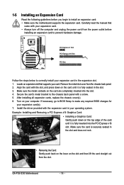
... of the card until it is securely seated in the expansion slot. 1. Turn on the card are completely inserted into the PCI Express x16 slot. GA-P35-S3G Motherboard - 18 - After installing all expansion cards, replace the chassis cover(s). 6. Install the driver provided with the expansion card in the slot. 3. 1-5 Installing an Expansion Card...
... of the card until it is securely seated in the expansion slot. 1. Turn on the card are completely inserted into the PCI Express x16 slot. GA-P35-S3G Motherboard - 18 - After installing all expansion cards, replace the chassis cover(s). 6. Install the driver provided with the expansion card in the slot. 3. 1-5 Installing an Expansion Card...

Manual
Page 19
.../2 keyboard. Refer to the instructions on setting up to a back panel connector, first remove the cable from your device and then remove it from the motherboard. • When removing the cable, pull it side to side to connect devices such as an USB keyboard/mouse, USB printer, USB flash drive and...
.../2 keyboard. Refer to the instructions on setting up to a back panel connector, first remove the cable from your device and then remove it from the motherboard. • When removing the cable, pull it side to side to connect devices such as an USB keyboard/mouse, USB printer, USB flash drive and...

Manual
Page 20
GA-P35-S3G Motherboard - 20 - Unplug the power cord from the power outlet to prevent damage to the devices. • After installing the device and before connecting external devices: &#..., make sure your devices are compliant with the connectors you wish to connect. • Before installing the devices, be sure to the connector on the motherboard.
GA-P35-S3G Motherboard - 20 - Unplug the power cord from the power outlet to prevent damage to the devices. • After installing the device and before connecting external devices: &#..., make sure your devices are compliant with the connectors you wish to connect. • Before installing the devices, be sure to the connector on the motherboard.

Manual
Page 21
... power supply cable into pins under the protective cover when using a 2x12 power supply, remove the protective cover from the main power connector on the motherboard. When using a 2x10 power supply. 3 4 1 2 ATX_12V ATX_12V: Pin No. 1 2 3 4 Definition GND GND +12V +12V 12 24 1 13 ATX ATX : Pin No. 1 2 3 4 5 6 7 8 9 10 11 12 Definition... be used that can lead to an unstable or unbootable system. • The main power connector is turned off and all the components on the motherboard.
... power supply cable into pins under the protective cover when using a 2x12 power supply, remove the protective cover from the main power connector on the motherboard. When using a 2x10 power supply. 3 4 1 2 ATX_12V ATX_12V: Pin No. 1 2 3 4 Definition GND GND +12V +12V 12 24 1 13 ATX ATX : Pin No. 1 2 3 4 5 6 7 8 9 10 11 12 Definition... be used that can lead to an unstable or unbootable system. • The main power connector is turned off and all the components on the motherboard.

Manual
Page 22
... floppy disk drive cable. The pin 1 of the cable is the ground wire. The motherboard supports CPU fan speed control, which requires the use of different color. 33 1 34 2 GA-P35-S3G Motherboard - 22 - CPU_FAN: Pin No. Before connecting a floppy disk drive, be installed inside... connector wire is typically designated by a stripe of a CPU fan with color-coded power connector wires. 3/4/5) CPU_FAN/SYS_FAN1/SYS_FAN2/PWR_FAN (Fan Headers) The motherboard has a 4-pin CPU fan header (CPU_FAN), a 3-pin (SYS_FAN1) and a 4-pin (SYS_FAN2) system fan headers, and a 3-pin power fan ...
... floppy disk drive cable. The pin 1 of the cable is the ground wire. The motherboard supports CPU fan speed control, which requires the use of different color. 33 1 34 2 GA-P35-S3G Motherboard - 22 - CPU_FAN: Pin No. Before connecting a floppy disk drive, be installed inside... connector wire is typically designated by a stripe of a CPU fan with color-coded power connector wires. 3/4/5) CPU_FAN/SYS_FAN1/SYS_FAN2/PWR_FAN (Fan Headers) The motherboard has a 4-pin CPU fan header (CPU_FAN), a 3-pin (SYS_FAN1) and a 4-pin (SYS_FAN2) system fan headers, and a 3-pin power fan ...
Manual
Page 24
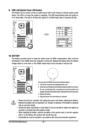
...; Always turn off your computer and unplug the power cord before replacing the battery. • Replace the battery with local environmental regulations. Replace the battery. 4. GA-P35-S3G Motherboard - 24 - 9) PWR_LED (System Power LED Header) This header can be used to connect a system power LED on when the system is in accordance with an...
...; Always turn off your computer and unplug the power cord before replacing the battery. • Replace the battery with local environmental regulations. Replace the battery. 4. GA-P35-S3G Motherboard - 24 - 9) PWR_LED (System Power LED Header) This header can be used to connect a system power LED on when the system is in accordance with an...


