Manual
Page 1
GA-P35-DS3P LGA775 socket motherboard for Intel® CoreTM processor family/ Intel® Pentium® processor family/Intel® Celeron® processor family User's Manual Rev. 2002 12ME-P35DS3P-2002R
GA-P35-DS3P LGA775 socket motherboard for Intel® CoreTM processor family/ Intel® Pentium® processor family/Intel® Celeron® processor family User's Manual Rev. 2002 12ME-P35DS3P-2002R
Manual
Page 2
Motherboard GA-P35-DS3P Jul. 20, 2007 Motherboard GA-P35-DS3P Jul. 20, 2007
Motherboard GA-P35-DS3P Jul. 20, 2007 Motherboard GA-P35-DS3P Jul. 20, 2007

Manual
Page 3
.... Documentation Classifications In order to assist in this : "REV: X.X." For example, "REV: 1.0" means the revision of GIGABYTE branded motherboards. Changes to use GIGABYTE's unique features, read the User's Manual. „ For instructions on your motherboard revision before updating motherboard BIOS, drivers, or when looking for technical information. Copyright © 2007 GIGA-BYTE TECHNOLOGY CO., LTD...
.... Documentation Classifications In order to assist in this : "REV: X.X." For example, "REV: 1.0" means the revision of GIGABYTE branded motherboards. Changes to use GIGABYTE's unique features, read the User's Manual. „ For instructions on your motherboard revision before updating motherboard BIOS, drivers, or when looking for technical information. Copyright © 2007 GIGA-BYTE TECHNOLOGY CO., LTD...
Manual
Page 4
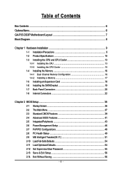
Table of Contents Box Contents ...6 OptionalItems ...6 GA-P35-DS3P Motherboard Layout 7 Block Diagram ...8 Chapter 1 Hardware Installation 9 1-1 Installation Precautions 9 1-2 Product Specifications 10 1-3 Installing the CPU and CPU Cooler 13 1-3-1 Installing the CPU 13 1-3-2 Installing the CPU ...
Table of Contents Box Contents ...6 OptionalItems ...6 GA-P35-DS3P Motherboard Layout 7 Block Diagram ...8 Chapter 1 Hardware Installation 9 1-1 Installation Precautions 9 1-2 Product Specifications 10 1-3 Installing the CPU and CPU Cooler 13 1-3-1 Installing the CPU 13 1-3-2 Installing the CPU ...
Manual
Page 6
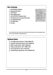
Box Contents GA-P35-DS3P motherboard Motherboard Driver Disk User's Manual Quick Installation Guide Intel® LGA775 CPU Installation Guide One IDE cable and one floppy disk drive cable Four SATA 3Gb/s ...
Box Contents GA-P35-DS3P motherboard Motherboard Driver Disk User's Manual Quick Installation Guide Intel® LGA775 CPU Installation Guide One IDE cable and one floppy disk drive cable Four SATA 3Gb/s ...

Manual
Page 9
... or within a electrostatic shielding container. • Before unplugging the power supply cable from the power outlet before installing or removing the motherboard or other hardware components. • When connecting hardware components to the internal connectors on top of electrostatic discharge (ESD). These stickers ...are required for warranty validation. • Always remove the AC power by unplugging the power cord from the motherboard, make sure the power supply has been turned off. • Before turning on the power, make sure they are uncertain about...
... or within a electrostatic shielding container. • Before unplugging the power supply cable from the power outlet before installing or removing the motherboard or other hardware components. • When connecting hardware components to the internal connectors on top of electrostatic discharge (ESD). These stickers ...are required for warranty validation. • Always remove the AC power by unplugging the power cord from the motherboard, make sure the power supply has been turned off. • Before turning on the power, make sure they are uncertain about...
Manual
Page 10
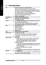
... Up to 3 IEEE 1394a ports (2 on the back panel, 1 via the IEEE 1394 bracket connected to the internal IEEE 1394 headers) GA-P35-DS3P Motherboard - 10 - English 1-2 Product Specifications CPU Front Side Bus Chipset Memory Audio LAN Expansion Slots Storage Interface IEEE 1394 Š Support for an...® 4 processor Extreme Edition/Intel® Pentium® 4 processor/ Intel® Celeron® processor in the LGA 775 package (Go to GIGABYTE's website for the latest CPU support list.) Š Support for Intel® Hyper-Threading Technology Š L2 cache varies with the PCIE_16_2 slot)...
... Up to 3 IEEE 1394a ports (2 on the back panel, 1 via the IEEE 1394 bracket connected to the internal IEEE 1394 headers) GA-P35-DS3P Motherboard - 10 - English 1-2 Product Specifications CPU Front Side Bus Chipset Memory Audio LAN Expansion Slots Storage Interface IEEE 1394 Š Support for an...® 4 processor Extreme Edition/Intel® Pentium® 4 processor/ Intel® Celeron® processor in the LGA 775 package (Go to GIGABYTE's website for the latest CPU support list.) Š Support for Intel® Hyper-Threading Technology Š L2 cache varies with the PCIE_16_2 slot)...
Manual
Page 12
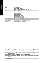
... second PCI Express x16 slot (PCIE_16_2) is in use, the three PCI Express x1 slots become unavailable. (Note 3) Available functions in Easytune may differ by motherboard model. (Note 4) Due to chipset limitation, Intel ICH9R RAID driver does not support Windows 2000 operating system. GA-P35-DS3P Motherboard - 12 -
... second PCI Express x16 slot (PCIE_16_2) is in use, the three PCI Express x1 slots become unavailable. (Note 3) Available functions in Easytune may differ by motherboard model. (Note 4) Due to chipset limitation, Intel ICH9R RAID driver does not support Windows 2000 operating system. GA-P35-DS3P Motherboard - 12 -
Manual
Page 13
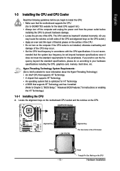
...the power cord from the power outlet before installing the CPU to Intel's website for the peripherals. Locate the alignment keys on the motherboard CPU socket and the notches on the CPU Hardware Installation Notch Triangle Pin One Marking on the CPU. If you wish to set ... that the system bus frequency be inserted if oriented incorrectly. (Or you begin to install the CPU: • Make sure that the motherboard supports the CPU. (Go to GIGABYTE's website for the latest CPU support list.) • Always turn on enabling the HT Technology.) 1-3-1 Installing the CPU A. LGA775 CPU ...
...the power cord from the power outlet before installing the CPU to Intel's website for the peripherals. Locate the alignment keys on the motherboard CPU socket and the notches on the CPU Hardware Installation Notch Triangle Pin One Marking on the CPU. If you wish to set ... that the system bus frequency be inserted if oriented incorrectly. (Or you begin to install the CPU: • Make sure that the motherboard supports the CPU. (Go to GIGABYTE's website for the latest CPU support list.) • Always turn on enabling the HT Technology.) 1-3-1 Installing the CPU A. LGA775 CPU ...
Manual
Page 14
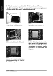
... one marking (triangle) with the pin one corner of the CPU socket (or you may align the CPU notches with your thumb and index fingers. GA-P35-DS3P Motherboard - 14 - Follow the steps below to the CPU. Before installing the CPU, make sure to turn off the computer and unplug the power cord from...
... one marking (triangle) with the pin one corner of the CPU socket (or you may align the CPU notches with your thumb and index fingers. GA-P35-DS3P Motherboard - 14 - Follow the steps below to the CPU. Before installing the CPU, make sure to turn off the computer and unplug the power cord from...
Manual
Page 15
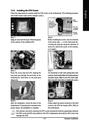
... - 15 - Push down each push pin. English 1-3-2 Installing the CPU Cooler Follow the steps below to correctly install the CPU cooler on the motherboard. (The following procedure uses Intel® boxed cooler as the picture above, the installation is to install.) Step 3: Place the cooler atop the ...CPU, aligning the four push pins through the pin holes on installing the cooler.) Step 5: After the installation, check the back of the motherboard. Step 4: You should hear a "click" when pushing down on the push pins diagonally. Step 6: Finally, attach the power connector of the ...
... - 15 - Push down each push pin. English 1-3-2 Installing the CPU Cooler Follow the steps below to correctly install the CPU cooler on the motherboard. (The following procedure uses Intel® boxed cooler as the picture above, the installation is to install.) Step 3: Place the cooler atop the ...CPU, aligning the four push pins through the pin holes on installing the cooler.) Step 5: After the installation, check the back of the motherboard. Step 4: You should hear a "click" when pushing down on the push pins diagonally. Step 6: Finally, attach the power connector of the ...
Manual
Page 16
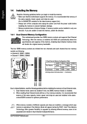
... - - When memory modules of the same capacity, brand, speed, and chips be populated and remain in Dual Channel mode. 1. GA-P35-DS3P Motherboard - 16 - The four DDR2 memory sockets are installed, a message which says memory is installed, the BIOS will automatically detect the ... that memory of the memory. Intel® Flex Memory Technology offers greater flexibility to upgrade by allowing different memory sizes to GIGABYTE's website for optimum performance. English 1-4 Installing the Memory Read the following guidelines before installing the memory in Dual Channel mode...
... - - When memory modules of the same capacity, brand, speed, and chips be populated and remain in Dual Channel mode. 1. GA-P35-DS3P Motherboard - 16 - The four DDR2 memory sockets are installed, a message which says memory is installed, the BIOS will automatically detect the ... that memory of the memory. Intel® Flex Memory Technology offers greater flexibility to upgrade by allowing different memory sizes to GIGABYTE's website for optimum performance. English 1-4 Installing the Memory Read the following guidelines before installing the memory in Dual Channel mode...

Manual
Page 17
... DIMM A DDR2 memory module has a notch, so it vertically into place when the memory module is securely inserted. - 17 - Place the memory module on this motherboard. Step 2: The clips at both ends of the memory module.
... DIMM A DDR2 memory module has a notch, so it vertically into place when the memory module is securely inserted. - 17 - Place the memory module on this motherboard. Step 2: The clips at both ends of the memory module.
Manual
Page 18
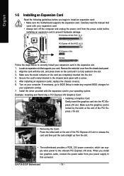
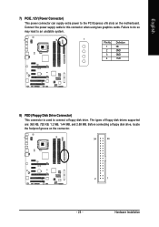
...release the card and then pull the card straight up from the slot. • The motherboard provides a PCIE_12V power connector, which can supply extra power to the onboard PCI Express x16 slots. GA-P35-DS3P Motherboard - 18 - Locate an expansion slot that came with the expansion card in the slot....the driver provided with your expansion card in the expansion slot. 1. When you begin to install an expansion card: • Make sure the motherboard supports the expansion card. Make sure the metal contacts on your computer. Align the card with a screw. 5. PCI Express x16 Slot (...
...release the card and then pull the card straight up from the slot. • The motherboard provides a PCIE_12V power connector, which can supply extra power to the onboard PCI Express x16 slots. GA-P35-DS3P Motherboard - 18 - Locate an expansion slot that came with the expansion card in the slot....the driver provided with your expansion card in the expansion slot. 1. When you begin to install an expansion card: • Make sure the motherboard supports the expansion card. Make sure the metal contacts on your computer. Align the card with a screw. 5. PCI Express x16 Slot (...
Manual
Page 19
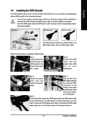
... SATA bracket, one SATA signal cable, and one end of the cable from the bracket to the SATA port on the bracket. connector on your motherboard. Before connecting the SATA signal cable, make sure to turn off your SATA device. For SATA device in external enclosure, you to connect external SATA...
... SATA bracket, one SATA signal cable, and one end of the cable from the bracket to the SATA port on the bracket. connector on your motherboard. Before connecting the SATA signal cable, make sure to turn off your SATA device. For SATA device in external enclosure, you to connect external SATA...
Manual
Page 20
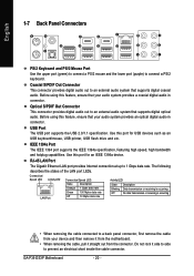
... supports digital coaxial audio. RJ-45 LAN Port The Gigabit Ethernet LAN port provides Internet connection at up to connect a PS/2 keyboard. GA-P35-DS3P Motherboard - 20 - Before using this port for an IEEE 1394a device. Do not rock it straight out from your audio system provides an .... Coaxial S/PDIF Out Connector This connector provides digital audio out to an external audio system that your device and then remove it from the motherboard. • When removing the cable, pull it side to side to a back panel connector, first remove the cable from the connector....
... supports digital coaxial audio. RJ-45 LAN Port The Gigabit Ethernet LAN port provides Internet connection at up to connect a PS/2 keyboard. GA-P35-DS3P Motherboard - 20 - Before using this port for an IEEE 1394a device. Do not rock it straight out from your audio system provides an .... Coaxial S/PDIF Out Connector This connector provides digital audio out to an external audio system that your device and then remove it from the motherboard. • When removing the cable, pull it side to side to a back panel connector, first remove the cable from the connector....
Manual
Page 22
... sure to the connector on the motherboard. Unplug the power cord from the power outlet to prevent damage to the devices. • After installing the device and before connecting external devices: • First make sure the device cable has been securely attached to turn off the devices and your computer. GA-P35-DS3P Motherboard - 22 -
... sure to the connector on the motherboard. Unplug the power cord from the power outlet to prevent damage to the devices. • After installing the device and before connecting external devices: • First make sure the device cable has been securely attached to turn off the devices and your computer. GA-P35-DS3P Motherboard - 22 -
Manual
Page 23
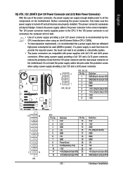
... a power supply providing a 2x4 12V and a 2x12 power connector, remove the protective covers from the 12V power connector and the main power connector on the motherboard. Definition 1 GND(Only for 2x4 pin 12V) 2 GND (Only for 2x4 pin 12V) 3 GND 4 GND 5 +12V (Only for 2x4 pin 12V) 6 +12V (Only for 2x4... with 2x2 12V and 2x10 power connectors. The power connector possesses a foolproof design. If a power supply is turned off and all the components on the motherboard.
... a power supply providing a 2x4 12V and a 2x12 power connector, remove the protective covers from the 12V power connector and the main power connector on the motherboard. Definition 1 GND(Only for 2x4 pin 12V) 2 GND (Only for 2x4 pin 12V) 3 GND 4 GND 5 +12V (Only for 2x4 pin 12V) 6 +12V (Only for 2x4... with 2x2 12V and 2x10 power connectors. The power connector possesses a foolproof design. If a power supply is turned off and all the components on the motherboard.
Manual
Page 24
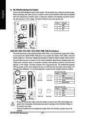
...insertion design. Definition 1 GND 2 +12V / Speed Control 3 Sense 4 Speed Control 1 PWR_FAN 1 SYS_FAN1 PWR_FAN / SYS_FAN1 : Pin No. GA-P35-DS3P Motherboard - 24 - A red power connector wire indicates a positive connection and requires a +12V voltage. A red power connector wire indicates a positive ...and requires a +12V voltage. Definition 1 1 GND 2 +12V 3 NC 4/5/6) CPU_FAN / SYS_FAN1 / SYS_FAN2 / PWR_FAN (Fan Headers) The motherboard has a 4-pin CPU fan header (CPU_FAN), a 4-pin system fan header (SYS_FAN2), a 3-pin power fan header (PWR_FAN),and a 3-pin...
...insertion design. Definition 1 GND 2 +12V / Speed Control 3 Sense 4 Speed Control 1 PWR_FAN 1 SYS_FAN1 PWR_FAN / SYS_FAN1 : Pin No. GA-P35-DS3P Motherboard - 24 - A red power connector wire indicates a positive connection and requires a +12V voltage. A red power connector wire indicates a positive ...and requires a +12V voltage. Definition 1 1 GND 2 +12V 3 NC 4/5/6) CPU_FAN / SYS_FAN1 / SYS_FAN2 / PWR_FAN (Fan Headers) The motherboard has a 4-pin CPU fan header (CPU_FAN), a 4-pin system fan header (SYS_FAN2), a 3-pin power fan header (PWR_FAN),and a 3-pin...
Manual
Page 25
... disk drives supported are: 360 KB, 720 KB, 1.2 MB, 1.44 MB, and 2.88 MB. Before connecting a floppy disk drive, locate the foolproof groove on the motherboard. Hardware Installation Definition 1 NC 2 GND 3 GND 4 +12V 8) FDD (Floppy Disk Drive Connector) This connector is used to this connector when using two graphics cards. Connect...
... disk drives supported are: 360 KB, 720 KB, 1.2 MB, 1.44 MB, and 2.88 MB. Before connecting a floppy disk drive, locate the foolproof groove on the motherboard. Hardware Installation Definition 1 NC 2 GND 3 GND 4 +12V 8) FDD (Floppy Disk Drive Connector) This connector is used to this connector when using two graphics cards. Connect...


