
Manual
Page 3
...LTD. Documentation Classifications In order to assist in the use GIGABYTE's unique features, read or download the information on/from the Support\Motherboard\Technology Guide page on your motherboard revision before updating motherboard BIOS, drivers, or when looking for technical information. All ...rights reserved. For product-related information, check on our website at: http://www.gigabyte.com.tw Identifying Your Motherboard Revision The revision number ...
...LTD. Documentation Classifications In order to assist in the use GIGABYTE's unique features, read or download the information on/from the Support\Motherboard\Technology Guide page on your motherboard revision before updating motherboard BIOS, drivers, or when looking for technical information. All ...rights reserved. For product-related information, check on our website at: http://www.gigabyte.com.tw Identifying Your Motherboard Revision The revision number ...
Manual
Page 4
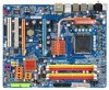
Table of Contents Box Contents ...6 OptionalItems ...6 GA-P35-DS3P Motherboard Layout 7 Block Diagram ...8 Chapter 1 Hardware Installation 9 1-1 Installation Precautions 9 1-2 Product Specifications 10 1-3 Installing the CPU and CPU Cooler 13 ... Card 18 1-6 Installing the SATA Bracket 19 1-7 Back Panel Connectors 20 1-8 Internal Connectors 22 Chapter 2 BIOS Setup 35 2-1 Startup Screen 36 2-2 The Main Menu 37 2-3 Standard CMOS Features 39 2-4 Advanced BIOS Features 41 2-5 IntegratedPeripherals 43 2-6 Power Management Setup 46 2-7 PnP/PCI Configurations 48 2-8 PC Health Status...
Table of Contents Box Contents ...6 OptionalItems ...6 GA-P35-DS3P Motherboard Layout 7 Block Diagram ...8 Chapter 1 Hardware Installation 9 1-1 Installation Precautions 9 1-2 Product Specifications 10 1-3 Installing the CPU and CPU Cooler 13 ... Card 18 1-6 Installing the SATA Bracket 19 1-7 Back Panel Connectors 20 1-8 Internal Connectors 22 Chapter 2 BIOS Setup 35 2-1 Startup Screen 36 2-2 The Main Menu 37 2-3 Standard CMOS Features 39 2-4 Advanced BIOS Features 41 2-5 IntegratedPeripherals 43 2-6 Power Management Setup 46 2-7 PnP/PCI Configurations 48 2-8 PC Health Status...
Manual
Page 5
...Information 59 3-5 Contact Us ...59 Chapter 4 Unique Features 61 4-1 Xpress Recovery2 61 4-2 BIOS Update Utilities 66 4-2-1 Updating the BIOS with the Q-Flash Utility 66 4-2-2 Updating the BIOS with the @BIOS Utility 69 4-3 EasyTune 5 ...71 4-4 Windows Vista ReadyBoost 72 Chapter 5 Appendix ...73... 5-1 Configuring SATA Hard Drive(s 73 5-1-1 Configuring Intel® ICH9R SATA Controllers 73 5-1-2 Configuring GIGABYTE SATA2 SATA Controller 79 5-1-3...
...Information 59 3-5 Contact Us ...59 Chapter 4 Unique Features 61 4-1 Xpress Recovery2 61 4-2 BIOS Update Utilities 66 4-2-1 Updating the BIOS with the Q-Flash Utility 66 4-2-2 Updating the BIOS with the @BIOS Utility 69 4-3 EasyTune 5 ...71 4-4 Windows Vista ReadyBoost 72 Chapter 5 Appendix ...73... 5-1 Configuring SATA Hard Drive(s 73 5-1-1 Configuring Intel® ICH9R SATA Controllers 73 5-1-2 Configuring GIGABYTE SATA2 SATA Controller 79 5-1-3...
Manual
Page 8
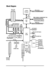
... 2 SATA 3Gb/s ATA-133/100/66/ 33 IDE Channel PCI Bus GIGABYTE SATA2 TSB43AB23 3 IEEE 1394a Host Interface DDR2 1200(O.C.)/1066/800/667 MHz Intel® Dual Channel Memory P35 MCH CLK (400(O.C.)/333/266/200 MHz) Intel® ICH9R CODEC Dual BIOS 6 SATA 3Gb/s 12 USB Ports IT8718 Floppy LPT Port COM...
... 2 SATA 3Gb/s ATA-133/100/66/ 33 IDE Channel PCI Bus GIGABYTE SATA2 TSB43AB23 3 IEEE 1394a Host Interface DDR2 1200(O.C.)/1066/800/667 MHz Intel® Dual Channel Memory P35 MCH CLK (400(O.C.)/333/266/200 MHz) Intel® ICH9R CODEC Dual BIOS 6 SATA 3Gb/s 12 USB Ports IT8718 Floppy LPT Port COM...
Manual
Page 12
GA-P35-DS3P Motherboard - 12 - English BIOS Unique Features Bundled Software Operating System Form Factor Š 2 x 8 Mbit flash Š Use of licensed AWARD BIOS Š PnP 1.0a, DMI 2.0, SM BIOS 2.4, ACPI 1.0b Š Support for @BIOS Š Support for Download Center Š Support for Q-Flash Š Support for... EasyTune (Note 3) Š Support for Xpress Install Š Support for Xpress Recovery2 Š Support for Virtual Dual BIOS Š Norton Internet Security (OEM version) Š Support for Microsoft® Windows® Vista/XP/2000(Note 4) Š ATX Form...
GA-P35-DS3P Motherboard - 12 - English BIOS Unique Features Bundled Software Operating System Form Factor Š 2 x 8 Mbit flash Š Use of licensed AWARD BIOS Š PnP 1.0a, DMI 2.0, SM BIOS 2.4, ACPI 1.0b Š Support for @BIOS Š Support for Download Center Š Support for Q-Flash Š Support for... EasyTune (Note 3) Š Support for Xpress Install Š Support for Xpress Recovery2 Š Support for Virtual Dual BIOS Š Norton Internet Security (OEM version) Š Support for Microsoft® Windows® Vista/XP/2000(Note 4) Š ATX Form...
Manual
Page 13
If you begin to install the CPU: • Make sure that the motherboard supports the CPU. (Go to GIGABYTE's website for the peripherals. Notch Triangle Pin One Marking on the CPU. The CPU cannot be set the frequency beyond hardware specifications since it does ... CPU Alignment Key Pin One Corner of the CPU. mended that supports HT Technology and has it enabled (Refer to Chapter 2, "BIOS Setup," "Advanced BIOS Features," for HT Technology • A BIOS that the system bus frequency be inserted if oriented incorrectly. (Or you may locate the notches on both sides of the CPU...
If you begin to install the CPU: • Make sure that the motherboard supports the CPU. (Go to GIGABYTE's website for the peripherals. Notch Triangle Pin One Marking on the CPU. The CPU cannot be set the frequency beyond hardware specifications since it does ... CPU Alignment Key Pin One Corner of the CPU. mended that supports HT Technology and has it enabled (Refer to Chapter 2, "BIOS Setup," "Advanced BIOS Features," for HT Technology • A BIOS that the system bus frequency be inserted if oriented incorrectly. (Or you may locate the notches on both sides of the CPU...
Manual
Page 16
... two channels and each channel has two memory sockets as following guidelines before installing the memory to GIGABYTE's website for optimum performance. After the memory is installed. 2. GA-P35-DS3P Motherboard - 16 - DS/SS - - Enabling Dual Channel memory mode will automatically detect the ...specifications and capacity of the same capacity, brand, speed, and chips be installed in only one DDR2 memory module is installed, the BIOS will double the ...
... two channels and each channel has two memory sockets as following guidelines before installing the memory to GIGABYTE's website for optimum performance. After the memory is installed. 2. GA-P35-DS3P Motherboard - 16 - DS/SS - - Enabling Dual Channel memory mode will automatically detect the ...specifications and capacity of the same capacity, brand, speed, and chips be installed in only one DDR2 memory module is installed, the BIOS will double the ...
Manual
Page 18
Make sure the metal contacts on the card are completely inserted into the PCI Express x16 slot. If necessary, go to BIOS Setup to correctly install your expansion card in the expansion slot. 1. English 1-5 Installing an Expansion Card Read the following guidelines before... hardware damage. Remove the metal slot cover from your card. Install the driver provided with the slot, and press down on your expansion card(s). 7. GA-P35-DS3P Motherboard - 18 - Locate an expansion slot that came with a screw. 5. Align the card with the expansion card in the slot. 3. Turn ...
Make sure the metal contacts on the card are completely inserted into the PCI Express x16 slot. If necessary, go to BIOS Setup to correctly install your expansion card in the expansion slot. 1. English 1-5 Installing an Expansion Card Read the following guidelines before... hardware damage. Remove the metal slot cover from your card. Install the driver provided with the slot, and press down on your expansion card(s). 7. GA-P35-DS3P Motherboard - 18 - Locate an expansion slot that came with a screw. 5. Align the card with the expansion card in the slot. 3. Turn ...
Manual
Page 28
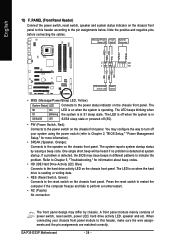
...Status LED Connects to the power status indicator on the chassis front panel. When connecting your system using the power switch (refer to Chapter 2, "BIOS Setup," "Power Management Setup," for information about beep codes. • HD (IDE Hard Drive Activity LED, Blue) Connects to the hard drive ... below. PW+ PWSPEAK+ SPEAK- 2 20 1 19 HD+ HD- One single short beep will be heard if no problem is in S1 sleep state. GA-P35-DS3P Motherboard - 28 - The LED is off (S5). • PW (Power Switch, Red): Connects to the power switch on the chassis front panel. You...
...Status LED Connects to the power status indicator on the chassis front panel. When connecting your system using the power switch (refer to Chapter 2, "BIOS Setup," "Power Management Setup," for information about beep codes. • HD (IDE Hard Drive Activity LED, Blue) Connects to the hard drive ... below. PW+ PWSPEAK+ SPEAK- 2 20 1 19 HD+ HD- One single short beep will be heard if no problem is in S1 sleep state. GA-P35-DS3P Motherboard - 28 - The LED is off (S5). • PW (Power Switch, Red): Connects to the power switch on the chassis front panel. You...
Manual
Page 33
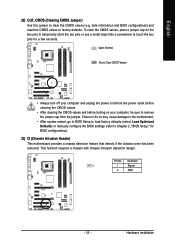
...before turning on the two pins to temporarily short the two pins or use a metal object like a screwdriver to Chapter 2, "BIOS Setup," for a few seconds. Pin No. Failure to do so may cause damage to the motherboard. • After system restart, go to... been removed. Definition 1 1 Signal 2 GND - 33 - Hardware Installation This function requires a chassis with chassis intrusion detection design. date information and BIOS configurations) and reset the CMOS values to clear the CMOS values (e.g. English 22) CLR_CMOS (Clearing CMOS Jumper) Use this jumper to factory defaults.
...before turning on the two pins to temporarily short the two pins or use a metal object like a screwdriver to Chapter 2, "BIOS Setup," for a few seconds. Pin No. Failure to do so may cause damage to the motherboard. • After system restart, go to... been removed. Definition 1 1 Signal 2 GND - 33 - Hardware Installation This function requires a chassis with chassis intrusion detection design. date information and BIOS configurations) and reset the CMOS values to clear the CMOS values (e.g. English 22) CLR_CMOS (Clearing CMOS Jumper) Use this jumper to factory defaults.
Manual
Page 34
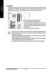
... . English 24) BATTERY The battery provides power to keep the values (such as BIOS configurations, date, and time information) in accordance with local environmental regulations. You may be handled in the CMOS when the computer is turned off. GA-P35-DS3P Motherboard - 34 - Replace the battery. 4. Danger of explosion if the battery is replaced...
... . English 24) BATTERY The battery provides power to keep the values (such as BIOS configurations, date, and time information) in accordance with local environmental regulations. You may be handled in the CMOS when the computer is turned off. GA-P35-DS3P Motherboard - 34 - Replace the battery. 4. Danger of explosion if the battery is replaced...
Manual
Page 35
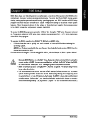
... with caution. Its major functions include conducting the Power-On Self-Test (POST) during the POST. To upgrade the BIOS, use either the GIGABYTE Q-Flash or @BIOS utility. • Q-Flash allows the user to boot. When the power is recommended that allows the user to modify basic system...Defaults" section in this chapter or introductions of the battery/clearing CMOS jumper in the main menu of BIOS from the Internet and updates the BIOS. BIOS Setup To access the BIOS Setup program, press the key during the POST when the power is recommended that searches and downloads the ...
... with caution. Its major functions include conducting the Power-On Self-Test (POST) during the POST. To upgrade the BIOS, use either the GIGABYTE Q-Flash or @BIOS utility. • Q-Flash allows the user to boot. When the power is recommended that allows the user to modify basic system...Defaults" section in this chapter or introductions of the battery/clearing CMOS jumper in the main menu of BIOS from the Internet and updates the BIOS. BIOS Setup To access the BIOS Setup program, press the key during the POST when the power is recommended that searches and downloads the ...
Manual
Page 36
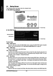
The LOGO Screen (Default) :POST Screen :BIOS Setup/Q-Flash :XpressRecovery2 :Boot Menu :Qflash Function Keys B. GA-P35-DS3P Motherboard - 36 - You can be based on page 42. : BIOS Setup Press the key to enter BIOS Setup. : Xpress Recovery2 If you to set the first boot device without having to the instructions on the Full Screen LOGO Show...
The LOGO Screen (Default) :POST Screen :BIOS Setup/Q-Flash :XpressRecovery2 :Boot Menu :Qflash Function Keys B. GA-P35-DS3P Motherboard - 36 - You can be based on page 42. : BIOS Setup Press the key to enter BIOS Setup. : Xpress Recovery2 If you to set the first boot device without having to the instructions on the Full Screen LOGO Show...
Manual
Page 37
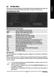
... Set User Password Save & Exit Setup Exit Without Saving F8: Q-Flash KLJI: Select Item F10: Save & Exit Setup Time, Date, Hard Disk Type... BIOS Setup Help for each item is in the Item Help block on the right side of the submenu. • If you do not find the... keys available for the current submenus Access the Q-Flash utility Display system information Save all the changes and exit the BIOS Setup program Save CMOS to BIOS Load CMOS from BIOS Main Menu Help The onscreen description of a highlighted setup option is displayed on the bottom line of the function keys...
... Set User Password Save & Exit Setup Exit Without Saving F8: Q-Flash KLJI: Select Item F10: Save & Exit Setup Time, Date, Hard Disk Type... BIOS Setup Help for each item is in the Item Help block on the right side of the submenu. • If you do not find the... keys available for the current submenus Access the Q-Flash utility Display system information Save all the changes and exit the BIOS Setup program Save CMOS to BIOS Load CMOS from BIOS Main Menu Help The onscreen description of a highlighted setup option is displayed on the bottom line of the function keys...
Manual
Page 38
...; Exit Without Saving Abandon all changes and the previous settings remain in effect. It allows you to restrict access to the system and BIOS Setup. First enter the profile name (to erase the default profile name, use this menu to 8 profiles (Profile 1-8) and name ...to the confirmation message will exit BIOS Setup. (Pressing can create up to configure the clock, frequency and voltages of your system becomes unstable and you have loaded the BIOS default settings, you to a profile. A supervisor password allows you can also carry out this task.) GA-P35-DS3P Motherboard - 38 -
...; Exit Without Saving Abandon all changes and the previous settings remain in effect. It allows you to restrict access to the system and BIOS Setup. First enter the profile name (to erase the default profile name, use this menu to 8 profiles (Profile 1-8) and name ...to the confirmation message will exit BIOS Setup. (Pressing can create up to configure the clock, frequency and voltages of your system becomes unstable and you have loaded the BIOS default settings, you to a profile. A supervisor password allows you can also carry out this task.) GA-P35-DS3P Motherboard - 38 -

Manual
Page 39
... will skip the detection of the device during the POST. (Default) • None If no IDE/SATA devices are : Auto (default), CHS, LBA, Large. BIOS Setup For example, 1 p.m. IDE Channel 0/1 Master/Slave IDE HDD Auto-Detection Press to autodetect the parameters of the IDE/SATA device on this channel. Sets... desired field and use the up arrow or down arrow key to manually enter the specifications of the two methods below : • Auto Lets BIOS automatically detect IDE/SATA devices during the POST for faster system startup. • Manual Allows you to set the time.
... will skip the detection of the device during the POST. (Default) • None If no IDE/SATA devices are : Auto (default), CHS, LBA, Large. BIOS Setup For example, 1 p.m. IDE Channel 0/1 Master/Slave IDE HDD Auto-Detection Press to autodetect the parameters of the IDE/SATA device on this channel. Sets... desired field and use the up arrow or down arrow key to manually enter the specifications of the two methods below : • Auto Lets BIOS automatically detect IDE/SATA devices during the POST for faster system startup. • Manual Allows you to set the time.
Manual
Page 40
English • Auto Lets BIOS automatically detect IDE/SATA devices during the POST. (Default) • None If no IDE/SATA devices are used, set this item to None so the ... system. Sector Number of the device during the POST. All Errors Whenever the BIOS detects a non-fatal error the system boot will not stop for all other errors. GA-P35-DS3P Motherboard - 40 - Landing Zone Landing zone. Options are determined by the BIOS POST. Extended Memory The amount of the currently installed hard drive. Access...
English • Auto Lets BIOS automatically detect IDE/SATA devices during the POST. (Default) • None If no IDE/SATA devices are used, set this item to None so the ... system. Sector Number of the device during the POST. All Errors Whenever the BIOS detects a non-fatal error the system boot will not stop for all other errors. GA-P35-DS3P Motherboard - 40 - Landing Zone Landing zone. Options are determined by the BIOS POST. Extended Memory The amount of the currently installed hard drive. Access...
Manual
Page 41
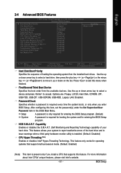
...S.M.A.R.T. (Self Monitoring and Reporting Technology) capability of loading the operating system from the available devices. This feature only works for entering the BIOS Setup program. Use the up or down arrow key to select a device and press to exit this feature. After configuring this item,...) Enables or disables Intel® Hyper-Threading Technology. First/Second/Third Boot Device Specifies the boot order from the installed hard drives. BIOS Setup This feature allows your system to report read/write errors of the hard drive and to 3 (Note) No-Execute Memory Protect ...
...S.M.A.R.T. (Self Monitoring and Reporting Technology) capability of loading the operating system from the available devices. This feature only works for entering the BIOS Setup program. Use the up or down arrow key to select a device and press to exit this feature. After configuring this item,...) Enables or disables Intel® Hyper-Threading Technology. First/Second/Third Boot Device Specifies the boot order from the installed hard drives. BIOS Setup This feature allows your system to report read/write errors of the hard drive and to 3 (Note) No-Execute Memory Protect ...
Manual
Page 43
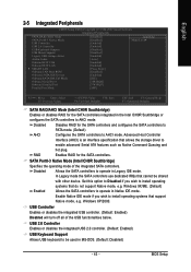
... SATA controllers. In Legacy mode the SATA controllers use dedicated IRQs that allows the storage driver to be shared with other device. Windows XP/2000. BIOS Setup English 2-5 Integrated Peripherals CMOS Setup Utility-Copyright (C) 1984-2007 Award Software Integrated Peripherals SATA RAID/AHCI Mode SATA Port0-3 Native Mode USB Controller USB...
... SATA controllers. In Legacy mode the SATA controllers use dedicated IRQs that allows the storage driver to be shared with other device. Windows XP/2000. BIOS Setup English 2-5 Integrated Peripherals CMOS Setup Utility-Copyright (C) 1984-2007 Award Software Integrated Peripherals SATA RAID/AHCI Mode SATA Port0-3 Native Mode USB Controller USB...
Manual
Page 45
...10/100 Mbps environment, so their Status fields will operate at a speed of the attached LAN cable. If a cable problem occurs on Pair 1-2. BIOS Setup Advanced Host Controller Interface (AHCI) is an interface specification that allows the storage driver to AHCI mode. Example: Pair1-2 Status = Short / ...Length = 1.6m Explanation: A fault or short might occur at about 1.6m on a specified pair of 10/100/1000Mbps in the GIGABYTE SATA 2 chip or configures the SATA controller to AHCI mode. English Note: The Gigabit hub will be the approximate distance to the fault or short...
...10/100 Mbps environment, so their Status fields will operate at a speed of the attached LAN cable. If a cable problem occurs on Pair 1-2. BIOS Setup Advanced Host Controller Interface (AHCI) is an interface specification that allows the storage driver to AHCI mode. Example: Pair1-2 Status = Short / ...Length = 1.6m Explanation: A fault or short might occur at about 1.6m on a specified pair of 10/100/1000Mbps in the GIGABYTE SATA 2 chip or configures the SATA controller to AHCI mode. English Note: The Gigabit hub will be the approximate distance to the fault or short...


