Manual
Page 4
... ...6 OptionalItems ...6 GA-P35-DS3L/S3L Motherboard Layout 7 Block Diagram ...8 Chapter 1 Hardware Installation 9 1-1 Installation Precautions 9 1-2 Product Specifications 10 1-3 Installing the CPU and CPU Cooler 13 1-3-1 Installing the CPU 13 1-3-2 Installing the CPU Cooler 15 1-4 Installing the Memory 16 1-4-1 Dual Channel Memory Configuration 16 1-4-2 Installing a Memory 17 1-5 Installing an Expansion Card 18 1-6 Back Panel Connectors 19...
... ...6 OptionalItems ...6 GA-P35-DS3L/S3L Motherboard Layout 7 Block Diagram ...8 Chapter 1 Hardware Installation 9 1-1 Installation Precautions 9 1-2 Product Specifications 10 1-3 Installing the CPU and CPU Cooler 13 1-3-1 Installing the CPU 13 1-3-2 Installing the CPU Cooler 15 1-4 Installing the Memory 16 1-4-1 Dual Channel Memory Configuration 16 1-4-2 Installing a Memory 17 1-5 Installing an Expansion Card 18 1-6 Back Panel Connectors 19...
Manual
Page 10
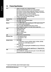
... 8 GB of system memory (Note 1) Š Dual channel memory architecture Š Support for DDR2 1066/800/667 MHz memory modules (Go to GIGABYTE's website for the latest memory support list.) Š Realtek ALC888 codec Š High Definition Audio Š 2/4/5.1/7.1-channel Š Support for S/PDIF ... supporting up to 1 floppy disk drive Š Integrated in the South Bridge Š Up to 12 USB 2.0/1.1 ports (6 on the back panel, 6 via the USB brackets connected to the internal USB headers) "*" Only the GA-P35-DS3L adopts All-Solid Capacitor design. GA-P35-DS3L/S3L Motherboard - 10 -
... 8 GB of system memory (Note 1) Š Dual channel memory architecture Š Support for DDR2 1066/800/667 MHz memory modules (Go to GIGABYTE's website for the latest memory support list.) Š Realtek ALC888 codec Š High Definition Audio Š 2/4/5.1/7.1-channel Š Support for S/PDIF ... supporting up to 1 floppy disk drive Š Integrated in the South Bridge Š Up to 12 USB 2.0/1.1 ports (6 on the back panel, 6 via the USB brackets connected to the internal USB headers) "*" Only the GA-P35-DS3L adopts All-Solid Capacitor design. GA-P35-DS3L/S3L Motherboard - 10 -
Manual
Page 11
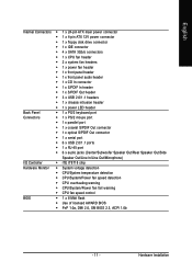
...x SATA 3Gb/s connectors Š 1 x CPU fan header Š 2 x system fan headers Š 1 x power fan header Š 1 x front panel header Š 1 x front panel audio header Š 1 x CD In connector Š 1 x S/PDIF In header Š 1 x S/PDIF Out header Š 3 x USB 2.0/1.1 headers... Š 1 x chassis intrusion header Š 1 x power LED header Back Panel Š 1 x PS/2 keyboard port Connectors Š 1 x PS/2 mouse port Š 1 x parallel port Š 1 x coaxial S/PDIF Out connector Š ...
...x SATA 3Gb/s connectors Š 1 x CPU fan header Š 2 x system fan headers Š 1 x power fan header Š 1 x front panel header Š 1 x front panel audio header Š 1 x CD In connector Š 1 x S/PDIF In header Š 1 x S/PDIF Out header Š 3 x USB 2.0/1.1 headers... Š 1 x chassis intrusion header Š 1 x power LED header Back Panel Š 1 x PS/2 keyboard port Connectors Š 1 x PS/2 mouse port Š 1 x parallel port Š 1 x coaxial S/PDIF Out connector Š ...
Manual
Page 18
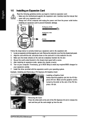
...slot. Make sure the metal contacts on your expansion card. • Always turn off the computer and unplug the power cord from the chassis back panel. 2. After installing all expansion cards, replace the chassis cover(s). 6. Turn on the card are completely inserted into the PCI Express x16 slot. ...before you begin to install an expansion card: • Make sure the motherboard supports the expansion card. GA-P35-DS3L/S3L Motherboard - 18 - If necessary, go to BIOS Setup to the chassis back panel with the slot, and press down on the card until it is locked by the latch at the...
...slot. Make sure the metal contacts on your expansion card. • Always turn off the computer and unplug the power cord from the chassis back panel. 2. After installing all expansion cards, replace the chassis cover(s). 6. Turn on the card are completely inserted into the PCI Express x16 slot. ...before you begin to install an expansion card: • Make sure the motherboard supports the expansion card. GA-P35-DS3L/S3L Motherboard - 18 - If necessary, go to BIOS Setup to the chassis back panel with the slot, and press down on the card until it is locked by the latch at the...
Manual
Page 19
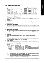
...Use this feature, ensure that your device and then remove it from your audio system provides an optical digital audio in connector. English 1-6 Back Panel Connectors PS/2 Keyboard and PS/2 Mouse Port Use the upper port (green) to connect a PS/2 mouse and the lower port (purple)...Port The USB port supports the USB 2.0/1.1 specification. Hardware Installation The parallel port is occurring • When removing the cable connected to a back panel connector, first remove the cable from the motherboard. • When removing the cable, pull it side to side to connect devices such as ...
...Use this feature, ensure that your device and then remove it from your audio system provides an optical digital audio in connector. English 1-6 Back Panel Connectors PS/2 Keyboard and PS/2 Mouse Port Use the upper port (green) to connect a PS/2 mouse and the lower port (purple)...Port The USB port supports the USB 2.0/1.1 specification. Hardware Installation The parallel port is occurring • When removing the cable connected to a back panel connector, first remove the cable from the motherboard. • When removing the cable, pull it side to side to connect devices such as ...
Manual
Page 25
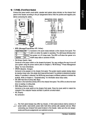
... Press the reset switch to restart the computer if the computer freezes and fails to perform a normal restart. • NC (Purple): No connection The front panel design may configure the way to turn off (S5). • PW (Power Switch, Red): Connects to the power switch on the chassis front.... Hardware Installation The LED is off when the system is in S3/S4/S5 Off S3/S4 sleep state or powered off your chassis front panel module to this header according to the pin assignments below. PW+ PWSPEAK+ SPEAK- 2 20 1 19 HD+ HD- The system reports system startup status by ...
... Press the reset switch to restart the computer if the computer freezes and fails to perform a normal restart. • NC (Purple): No connection The front panel design may configure the way to turn off (S5). • PW (Power Switch, Red): Connects to the power switch on the chassis front.... Hardware Installation The LED is off when the system is in S3/S4/S5 Off S3/S4 sleep state or powered off your chassis front panel module to this header according to the pin assignments below. PW+ PWSPEAK+ SPEAK- 2 20 1 19 HD+ HD- The system reports system startup status by ...
Manual
Page 26
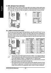
...S0 On S1 Blinking S3/S4/S5 Off 12) F_AUDIO (Front Panel Audio Header) The front panel audio header supports Intel High Definition audio (HD) and AC'97 audio. GA-P35-DS3L/S3L Motherboard - 26 - If your chassis front panel audio module to connect a system power LED on when the ... the module connector match the pin assignments of a single plug. Definition Pin No. You may connect your chassis provides an AC'97 front panel audio module, refer to the instructions on how to activate AC'97 functioninality via the audio software in Chapter 5, "Configuring 2/4/5.1/7.1-Channel Audio."...
...S0 On S1 Blinking S3/S4/S5 Off 12) F_AUDIO (Front Panel Audio Header) The front panel audio header supports Intel High Definition audio (HD) and AC'97 audio. GA-P35-DS3L/S3L Motherboard - 26 - If your chassis front panel audio module to connect a system power LED on when the ... the module connector match the pin assignments of a single plug. Definition Pin No. You may connect your chassis provides an AC'97 front panel audio module, refer to the instructions on how to activate AC'97 functioninality via the audio software in Chapter 5, "Configuring 2/4/5.1/7.1-Channel Audio."...
Manual
Page 67
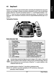
... of these components. OVERCLOCKING 2. GO 6. GIGABYTE Logo 10. setting page Enters the Smart-Fan setting page Enters the PC Health setting page Confirmation and Execution button Toggles between Easy and Advance Mode Displays panel of CPU frequency Shows the information of the... current function Visits GIGABYTE website Displays EasyTuneTM 5 help screen Quits or minimizes EasyTuneTM 5 Incorrectly doing overclock/overvoltage ...
... of these components. OVERCLOCKING 2. GO 6. GIGABYTE Logo 10. setting page Enters the Smart-Fan setting page Enters the PC Health setting page Confirmation and Execution button Toggles between Easy and Advance Mode Displays panel of CPU frequency Shows the information of the... current function Visits GIGABYTE website Displays EasyTuneTM 5 help screen Quits or minimizes EasyTuneTM 5 Incorrectly doing overclock/overvoltage ...
Manual
Page 69
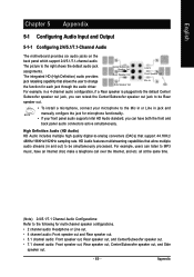
...Audio) HD Audio includes multiple high quality digital-to be Rear speaker out. • To install a microphone, connect your front panel audio supports Intel HD Audio standard, you can retask the Center/Subwoofer speaker out jack to be simultaneously processed. all at the ...English Chapter 5 Appendix 5-1 Configuring Audio Input and Output 5-1-1 Configuring 2/4/5.1/7.1-Channel Audio The motherboard provides six audio jacks on the back panel which support 2/4/5.1/7.1-channel audio. The picture to the following for each jack through the audio driver. Side Speaker Out Mic In ...
...Audio) HD Audio includes multiple high quality digital-to be Rear speaker out. • To install a microphone, connect your front panel audio supports Intel HD Audio standard, you can retask the Center/Subwoofer speaker out jack to be simultaneously processed. all at the ...English Chapter 5 Appendix 5-1 Configuring Audio Input and Output 5-1-1 Configuring 2/4/5.1/7.1-Channel Audio The motherboard provides six audio jacks on the back panel which support 2/4/5.1/7.1-channel audio. The picture to the following for each jack through the audio driver. Side Speaker Out Mic In ...

Manual
Page 70
... connect an audio device to the type of speaker configuration you connect. Select the device according to an audio jack, the Connected device box appears. GA-P35-DS3L/S3L Motherboard - 70 - Step 2: Click the Audio I/O tab. Doubleclick the icon to access the Audio Control Panel.
... connect an audio device to the type of speaker configuration you connect. Select the device according to an audio jack, the Connected device box appears. GA-P35-DS3L/S3L Motherboard - 70 - Step 2: Click the Audio I/O tab. Doubleclick the icon to access the Audio Control Panel.
Manual
Page 71
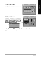
Configuring AC'97 Audio: If you can only have audio signals present on either the front or the back panel audio connections, but not both at the same time. - 71 - Configuring Sound Effect: You may configure an audio environment on the Audio I/O tab On the Global Connector Settings box, select the Disable front panel jack detection check box. When using an AC'97 front panel audio module, you want to activiate the AC'97 functionality. Click OK to connect an AC'97 front panel audio module, click the tool icon on the Sound Effect tab. Appendix C. English B.
Configuring AC'97 Audio: If you can only have audio signals present on either the front or the back panel audio connections, but not both at the same time. - 71 - Configuring Sound Effect: You may configure an audio environment on the Audio I/O tab On the Global Connector Settings box, select the Disable front panel jack detection check box. When using an AC'97 front panel audio module, you want to activiate the AC'97 functionality. Click OK to connect an AC'97 front panel audio module, click the tool icon on the Sound Effect tab. Appendix C. English B.
Manual
Page 72
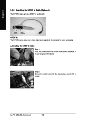
Optical S/PDIF In Coaxial S/PDIF In S/PDIF In: The S/PDIF in functionality. GA-P35-DS3L/S3L Motherboard - 72 - Installing the S/PDIF In Cable: Step 1: First, attach the connector at the end of the cable to the chassis back panel with a screw. Step 2: Secure the metal bracket to the SPDIF_I header on your motherboard. A. English 5-1-2 Installing the S/PDIF In Cable (Optional) The S/PDIF in cable provides S/PDIF in jacks allow you to input digital audio signals to the computer for audio processing.
Optical S/PDIF In Coaxial S/PDIF In S/PDIF In: The S/PDIF in functionality. GA-P35-DS3L/S3L Motherboard - 72 - Installing the S/PDIF In Cable: Step 1: First, attach the connector at the end of the cable to the chassis back panel with a screw. Step 2: Secure the metal bracket to the SPDIF_I header on your motherboard. A. English 5-1-2 Installing the S/PDIF In Cable (Optional) The S/PDIF in cable provides S/PDIF in jacks allow you to input digital audio signals to the computer for audio processing.
Manual
Page 74
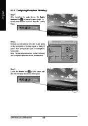
Step 2: Connect your microphone to the Mic in jack (pink) on the back panel or the Line in jack on the front panel and back panel cannot be used at the same time. Then configure the jack for microphone functionality. English 5-1-3 Configuring Microphone Recording Step 1: After installing the audio driver, ...the Audio Manager icon will appear in your system tray and click it to open the volume control panel GA-P35-DS3L/S3L Motherboard - 74 - Step 3: Locate the Volume icon in your system tray. Note: The microphone functions on the front...
Step 2: Connect your microphone to the Mic in jack (pink) on the back panel or the Line in jack on the front panel and back panel cannot be used at the same time. Then configure the jack for microphone functionality. English 5-1-3 Configuring Microphone Recording Step 1: After installing the audio driver, ...the Audio Manager icon will appear in your system tray and click it to open the volume control panel GA-P35-DS3L/S3L Motherboard - 74 - Step 3: Locate the Volume icon in your system tray. Note: The microphone functions on the front...
Manual
Page 75
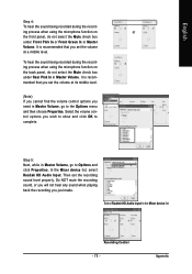
... Audio Input in Master Volume, go to the Options menu and then choose Properties. ing process when using the microphone function on or the front panel, do not select the Mute check box under Front Pink In or Front Green In in Master Volume, go to complete. Select the volume control... click OK to Options and click Properties. To hear the sound being recorded during the recording process when using the microphone function on the back panel, do not select the Mute check box under Rear Pink In in Master Volume. Do NOT mute the recording sound, or you will not hear...
... Audio Input in Master Volume, go to the Options menu and then choose Properties. ing process when using the microphone function on or the front panel, do not select the Mute check box under Front Pink In or Front Green In in Master Volume, go to complete. Select the volume control... click OK to Options and click Properties. To hear the sound being recorded during the recording process when using the microphone function on the back panel, do not select the Mute check box under Rear Pink In in Master Volume. Do NOT mute the recording sound, or you will not hear...


