
Manual
Page 4
...Heatsink from the Back of the Motherboard ..... 16 1-4 Installing the Memory 17 1-4-1 Dual Channel Memory Configuration 17 1-4-2 Installing a Memory 18 1-5 Installing an Expansion Card 19 1-6 Installing the SATA Bracket 21 1-7 Back Panel Connectors 22 1-8 Internal Connectors 24 Chapter 2 BIOS Setup 37 2-1 Startup Screen 38 2-2 The Main Menu 39 2-3 Standard CMOS Features 41 2-4 Advanced BIOS Features 43 2-5 IntegratedPeripherals 45 2-6 Power Management Setup 48 2-7 PnP/PCI Configurations 50 2-8 PC Health Status 51 2-9 MB Intelligent Tweaker(M.I.T 53 2-10 Load Fail-Safe Defaults...
...Heatsink from the Back of the Motherboard ..... 16 1-4 Installing the Memory 17 1-4-1 Dual Channel Memory Configuration 17 1-4-2 Installing a Memory 18 1-5 Installing an Expansion Card 19 1-6 Installing the SATA Bracket 21 1-7 Back Panel Connectors 22 1-8 Internal Connectors 24 Chapter 2 BIOS Setup 37 2-1 Startup Screen 38 2-2 The Main Menu 39 2-3 Standard CMOS Features 41 2-4 Advanced BIOS Features 43 2-5 IntegratedPeripherals 45 2-6 Power Management Setup 48 2-7 PnP/PCI Configurations 50 2-8 PC Health Status 51 2-9 MB Intelligent Tweaker(M.I.T 53 2-10 Load Fail-Safe Defaults...
Manual
Page 10
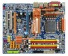
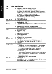
... Audio Š 2/4/5.1/7.1-channel Š Support for DTS (dts NEO:PC) Š Support for S/PDIF In/Out Š Support for SATA RAID 0, RAID 1, and JBOD Š T.I. the PCIE_16_2 supports x4.) Š 3 x PCI Express x1 slots (share with CPU Š 1333/1066/800 MHz FSB Š North Bridge: Intel® P35 Chipset Š South Bridge: Intel® ICH9R Š 4 x 1.8V DDR2 DIMM sockets supporting up to the internal IEEE 1394 headers) GA-P35-DQ6 Motherboard...
... Audio Š 2/4/5.1/7.1-channel Š Support for DTS (dts NEO:PC) Š Support for S/PDIF In/Out Š Support for SATA RAID 0, RAID 1, and JBOD Š T.I. the PCIE_16_2 supports x4.) Š 3 x PCI Express x1 slots (share with CPU Š 1333/1066/800 MHz FSB Š North Bridge: Intel® P35 Chipset Š South Bridge: Intel® ICH9R Š 4 x 1.8V DDR2 DIMM sockets supporting up to the internal IEEE 1394 headers) GA-P35-DQ6 Motherboard...

Manual
Page 12
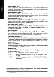
... physical memory is installed, the actual memory size displayed will be less than 4 GB. (Note 2) When the second PCI Express x16 slot (PCIE_16_2) is in use, the three PCI Express x1 slots become unavailable. (Note 3) Available functions in Easytune may differ by motherboard model. (Note 4) The adjustable CPU voltage range depends on the CPU being used. (Note 5) Due to chipset limitation, Intel ICH9R RAID driver does not support Windows 2000 operating system. Increase CPU voltage...
... physical memory is installed, the actual memory size displayed will be less than 4 GB. (Note 2) When the second PCI Express x16 slot (PCIE_16_2) is in use, the three PCI Express x1 slots become unavailable. (Note 3) Available functions in Easytune may differ by motherboard model. (Note 4) The adjustable CPU voltage range depends on the CPU being used. (Note 5) Due to chipset limitation, Intel ICH9R RAID driver does not support Windows 2000 operating system. Increase CPU voltage...

Manual
Page 27
... a 3-pin power fan header (PWR_FAN). When connecting a fan cable, be sure to this header. A red power connector wire indicates a positive connection and requires a +12V voltage. Most fans are not configuration jumper blocks. A red power connector wire indicates a positive connection and requires a +12V voltage. Definition 1 1 GND 2 +12V 3 NC • Be sure to connect fan cables to the fan headers to the CPU/North Bridge or the system may hang. • These fan headers are designed with color-coded power connector wires. Each fan header supplies a +12V power voltage...
... a 3-pin power fan header (PWR_FAN). When connecting a fan cable, be sure to this header. A red power connector wire indicates a positive connection and requires a +12V voltage. Most fans are not configuration jumper blocks. A red power connector wire indicates a positive connection and requires a +12V voltage. Definition 1 1 GND 2 +12V 3 NC • Be sure to connect fan cables to the fan headers to the CPU/North Bridge or the system may hang. • These fan headers are designed with color-coded power connector wires. Each fan header supplies a +12V power voltage...

Manual
Page 43
...for operating systems that supports this feature. HDD S.M.A.R.T. BIOS Setup English 2-4 Advanced BIOS Features CMOS Setup Utility-Copyright (C) 1984-2007 Award Software Advanced BIOS Features ` Hard Disk Boot Priority First Boot Device Second Boot Device Third Boot Device Password Check HDD S.M.A.R.T. Capability CPU Hyper-Threading (Note) Limit CPUID Max. Options are: Floppy, LS120, Hard Disk, CDROM, ZIP, USB-FDD, USB-ZIP, USB-CDROM, USB-HDD, Legacy LAN, Disabled. Use the up or down arrow key to select a hard drive, then press the plus key (or ) or the minus...
...for operating systems that supports this feature. HDD S.M.A.R.T. BIOS Setup English 2-4 Advanced BIOS Features CMOS Setup Utility-Copyright (C) 1984-2007 Award Software Advanced BIOS Features ` Hard Disk Boot Priority First Boot Device Second Boot Device Third Boot Device Password Check HDD S.M.A.R.T. Capability CPU Hyper-Threading (Note) Limit CPUID Max. Options are: Floppy, LS120, Hard Disk, CDROM, ZIP, USB-FDD, USB-ZIP, USB-CDROM, USB-HDD, Legacy LAN, Disabled. Use the up or down arrow key to select a hard drive, then press the plus key (or ) or the minus...
Manual
Page 44
... first PCIe x16 slot (PCIE_16_1) as the first display. (Note) This item is overheated. (Default: Enabled) CPU EIST Function (Note) Enables or disables Enhanced Intel SpeedStep Technology (EIST). GA-P35-DQ6 Motherboard - 44 - English Limit CPUID Max. With virtualization, one computer system can dynamically and effectively lower the CPU voltage and core frequency to limit CPUID maximum value. Sets PCI Express graphics card on CPU loading, Intel® EIST technology can function as multiple virtual systems. (Default: Enabled) Full Screen LOGO...
... first PCIe x16 slot (PCIE_16_1) as the first display. (Note) This item is overheated. (Default: Enabled) CPU EIST Function (Note) Enables or disables Enhanced Intel SpeedStep Technology (EIST). GA-P35-DQ6 Motherboard - 44 - English Limit CPUID Max. With virtualization, one computer system can dynamically and effectively lower the CPU voltage and core frequency to limit CPUID maximum value. Sets PCI Express graphics card on CPU loading, Intel® EIST technology can function as multiple virtual systems. (Default: Enabled) Full Screen LOGO...

Manual
Page 45
...2-5 Integrated Peripherals CMOS Setup Utility-Copyright (C) 1984-2007 Award Software Integrated Peripherals SATA RAID/AHCI Mode SATA Port0-3 Native Mode USB Controller USB 2.0 Controller USB Keyboard Support USB Mouse Support Legacy USB storage detect Azalia Codec Onboard H/W 1394 Onboard H/W LAN ` SMART LAN Onboard LAN Boot ROM Onboard SATA/IDE Device Onboard SATA/IDE Ctrl Mode Onboard Serial Port 1 Onboard Parallel Port Parallel Port Mode [Disabled] [Disabled] [Enabled] [Enabled] [Disabled] [Disabled] [Enabled] [Auto] [Enabled] [Enabled] [Press Enter] [Disabled] [Enabled] [IDE] [3F8/IRQ4...
...2-5 Integrated Peripherals CMOS Setup Utility-Copyright (C) 1984-2007 Award Software Integrated Peripherals SATA RAID/AHCI Mode SATA Port0-3 Native Mode USB Controller USB 2.0 Controller USB Keyboard Support USB Mouse Support Legacy USB storage detect Azalia Codec Onboard H/W 1394 Onboard H/W LAN ` SMART LAN Onboard LAN Boot ROM Onboard SATA/IDE Device Onboard SATA/IDE Ctrl Mode Onboard Serial Port 1 Onboard Parallel Port Parallel Port Mode [Disabled] [Disabled] [Enabled] [Enabled] [Disabled] [Disabled] [Enabled] [Auto] [Enabled] [Enabled] [Press Enter] [Disabled] [Enabled] [IDE] [3F8/IRQ4...

Manual
Page 46
... attached LAN cable. If no cable problem is attached to Disabled. GA-P35-DQ6 Motherboard - 46 - Refer to the fault or short. If no LAN cable is detected on the LAN cable connected to Disabled. Link Detected --> 100Mbps Cable Length= 30m Link Detected Cable Length Displays transmission speed Displays the approximate length of wires will appear: Start detecting at Port..... Onboard 1394 Function Enables or disables the onboard IEEE 1394 function. (Default: Enabled) Onboard H/W LAN Enables or disables the onboard LAN function. (Default: Enabled) If you wish to install...
... attached LAN cable. If no cable problem is attached to Disabled. GA-P35-DQ6 Motherboard - 46 - Refer to the fault or short. If no LAN cable is detected on the LAN cable connected to Disabled. Link Detected --> 100Mbps Cable Length= 30m Link Detected Cable Length Displays transmission speed Displays the approximate length of wires will appear: Start detecting at Port..... Onboard 1394 Function Enables or disables the onboard IEEE 1394 function. (Default: Enabled) Onboard H/W LAN Enables or disables the onboard LAN function. (Default: Enabled) If you wish to install...

Manual
Page 47
... the GIGABYTE SATA 2 chip. (Default: Enabled) Onboard SATA/IDE Ctrl Mode (GIGABYTE SATA2 Chip) Enables or disables RAID for the onboard parallel (LPT) port. Advanced Host Controller Interface (AHCI) is an interface specification that allows the storage driver to AHCI mode. Onboard LAN Boot ROM Allows you to decide whether to the fault or short. Options are : 378/IRQ7 (default), 278/IRQ5, 3BC/IRQ7, Disabled. Options are not used in a 10/100 Mbps environment, so their Status fields will operate at a normal speed of...
... the GIGABYTE SATA 2 chip. (Default: Enabled) Onboard SATA/IDE Ctrl Mode (GIGABYTE SATA2 Chip) Enables or disables RAID for the onboard parallel (LPT) port. Advanced Host Controller Interface (AHCI) is an interface specification that allows the storage driver to AHCI mode. Onboard LAN Boot ROM Allows you to decide whether to the fault or short. Options are : 378/IRQ7 (default), 278/IRQ5, 3BC/IRQ7, Disabled. Options are not used in a 10/100 Mbps environment, so their Status fields will operate at a normal speed of...

Manual
Page 52
...control CPU fan speed. A small portion of system memory will be set to the CPU temperature. GA-P35-DQ6 Motherboard - 52 - This feature requires the installation of CPU fan installed and sets the optimal CPU fan control mode. (Default) Voltage Sets Voltage mode for a 3-pin CPU fan or a 4-pin CPU fan. This item is configurable only if CPU Smart FAN Control is set for a 3-pin CPU fan. Auto Lets BIOS autodetect the type of Intel Host Embedded Control Interface (HECI) driver from the motherboard driver disk. Note: The Voltage mode can be shared when Intel® QST is enabled...
...control CPU fan speed. A small portion of system memory will be set to the CPU temperature. GA-P35-DQ6 Motherboard - 52 - This feature requires the installation of CPU fan installed and sets the optimal CPU fan control mode. (Default) Voltage Sets Voltage mode for a 3-pin CPU fan or a 4-pin CPU fan. This item is configurable only if CPU Smart FAN Control is set for a 3-pin CPU fan. Auto Lets BIOS autodetect the type of Intel Host Embedded Control Interface (HECI) driver from the motherboard driver disk. Note: The Voltage mode can be shared when Intel® QST is enabled...

Manual
Page 53
... CMOS Setup Utility-Copyright (C) 1984-2007 Award Software MB Intelligent Tweaker(M.I.T.) Robust Graphics Booster CPU Clock Ratio (Note) CPU Host Clock Control x CPU Host Frequency (Mhz) PCI Express Frequency (Mhz) C.I.A. 2 System Memory Multiplier (SPD) Memory Frequency (Mhz) 667 High Speed DRAM DLL Settings ******** System Voltage Optimized System Voltage Control DDR2 OverVoltage Control PCI-E OverVoltage Control FSB OverVoltage Control (G)MCH OverVoltage Control CPU Voltage Control Normal CPU Vcore ******** [Auto] [16X] [Disabled] 200 Auto [Disabled] [Auto] 667 [Option 1] [Manual...
... CMOS Setup Utility-Copyright (C) 1984-2007 Award Software MB Intelligent Tweaker(M.I.T.) Robust Graphics Booster CPU Clock Ratio (Note) CPU Host Clock Control x CPU Host Frequency (Mhz) PCI Express Frequency (Mhz) C.I.A. 2 System Memory Multiplier (SPD) Memory Frequency (Mhz) 667 High Speed DRAM DLL Settings ******** System Voltage Optimized System Voltage Control DDR2 OverVoltage Control PCI-E OverVoltage Control FSB OverVoltage Control (G)MCH OverVoltage Control CPU Voltage Control Normal CPU Vcore ******** [Auto] [16X] [Disabled] 200 Auto [Disabled] [Auto] 667 [Option 1] [Manual...

Manual
Page 58
... BIOS Setup without saving the changes made in BIOS Setup to the BIOS Setup Main Menu. Press or to return to the CMOS. GA-P35-DQ6 Motherboard - 58 - This saves the changes to the CMOS and exits the BIOS Setup program. English 2-13 Save & Exit Setup CMOS Setup Utility-Copyright (C) 1984-2007 Award Software ` Standard CMOS Features Load Fail-Safe Defaults ` Advanced BIOS Features Load Optimized Defaults ` Integrated Peripherals Set Supervisor Password ` Power Management Setup Save to CMOS and EXIT (SYe/tNU)?seYr Password ` PnP/PCI Configurations Save & Exit Setup...
... BIOS Setup without saving the changes made in BIOS Setup to the BIOS Setup Main Menu. Press or to return to the CMOS. GA-P35-DQ6 Motherboard - 58 - This saves the changes to the CMOS and exits the BIOS Setup program. English 2-13 Save & Exit Setup CMOS Setup Utility-Copyright (C) 1984-2007 Award Software ` Standard CMOS Features Load Fail-Safe Defaults ` Advanced BIOS Features Load Optimized Defaults ` Integrated Peripherals Set Supervisor Password ` Power Management Setup Save to CMOS and EXIT (SYe/tNU)?seYr Password ` PnP/PCI Configurations Save & Exit Setup...

Manual
Page 75
... Installation," to identify the SATA controller for the SATA port. (For example, on this motherboard, the SATAII0, SATAII1, SATAII2, SATAII3, SATAII4 and SATAII5 ports are supported by ICH9R Southbridge.) Then connect the power connector from your power supply to the hard drive. (Note 1) Skip this step if you use two hard drives with identical model and capacity). English Chapter 5 Appendix 5-1 Configuring SATA Hard Drive(s) To configure SATA hard drive(s), follow the steps below: A. Configure SATA controller mode in RAID BIOS. (Note 1) D. Appendix C . B. Configure a RAID...
... Installation," to identify the SATA controller for the SATA port. (For example, on this motherboard, the SATAII0, SATAII1, SATAII2, SATAII3, SATAII4 and SATAII5 ports are supported by ICH9R Southbridge.) Then connect the power connector from your power supply to the hard drive. (Note 1) Skip this step if you use two hard drives with identical model and capacity). English Chapter 5 Appendix 5-1 Configuring SATA Hard Drive(s) To configure SATA hard drive(s), follow the steps below: A. Configure SATA controller mode in RAID BIOS. (Note 1) D. Appendix C . B. Configure a RAID...

Manual
Page 76
GA-P35-DQ6 Motherboard - 76 - CMOS Setup Utility-Copyright (C) 1984-2007 Award Software Integrated Peripherals SATA RAID/AHCI Mode SATA Port0-3 Native Mode USB Controller USB 2.0 Controller USB Keyboard Support USB Mouse Support Legacy USB storage detect Azalia Codec Onboard H/W 1394 Onboard H/W LAN ` SMART LAN OnBoard LAN Boot ROM Onboard SATA/IDE Device Onboard SATA/IDE Ctrl Mode Onboard Serial Port 1 Onboard Parallel Port Parallel Port Mode [RAID] [Disabled] [Enabled] [Enabled] [Disabled] [Disabled] [Enabled] [Auto] [Enabled] [Enabled] [Press Enter] [Disabled] [Enabled] [IDE] [3F8/...
GA-P35-DQ6 Motherboard - 76 - CMOS Setup Utility-Copyright (C) 1984-2007 Award Software Integrated Peripherals SATA RAID/AHCI Mode SATA Port0-3 Native Mode USB Controller USB 2.0 Controller USB Keyboard Support USB Mouse Support Legacy USB storage detect Azalia Codec Onboard H/W 1394 Onboard H/W LAN ` SMART LAN OnBoard LAN Boot ROM Onboard SATA/IDE Device Onboard SATA/IDE Ctrl Mode Onboard Serial Port 1 Onboard Parallel Port Parallel Port Mode [RAID] [Disabled] [Enabled] [Enabled] [Disabled] [Disabled] [Enabled] [Auto] [Enabled] [Enabled] [Press Enter] [Disabled] [Enabled] [IDE] [3F8/...

Manual
Page 81
... power supply to IDE or AHCI, depending on your need. If you have and the BIOS version. - 81 - Then set the device boot order. CMOS Setup Utility-Copyright (C) 1984-2007 Award Software Integrated Peripherals SATA RAID/AHCI Mode SATA Port0-3 Native Mode USB Controller USB 2.0 Controller USB Keyboard Support USB Mouse Support Legacy USB storage detect Azalia Codec Onboard H/W 1394 Onboard H/W LAN ` SMART LAN OnBoard LAN Boot ROM Onboard SATA/IDE Device Onboard SATA/IDE Ctrl Mode Onboard Serial Port 1 Onboard Parallel Port Parallel Port Mode [Disabled] [Disabled] [Enabled] [Enabled...
... power supply to IDE or AHCI, depending on your need. If you have and the BIOS version. - 81 - Then set the device boot order. CMOS Setup Utility-Copyright (C) 1984-2007 Award Software Integrated Peripherals SATA RAID/AHCI Mode SATA Port0-3 Native Mode USB Controller USB 2.0 Controller USB Keyboard Support USB Mouse Support Legacy USB storage detect Azalia Codec Onboard H/W 1394 Onboard H/W LAN ` SMART LAN OnBoard LAN Boot ROM Onboard SATA/IDE Device Onboard SATA/IDE Ctrl Mode Onboard Serial Port 1 Onboard Parallel Port Parallel Port Mode [Disabled] [Disabled] [Enabled] [Enabled...

Manual
Page 82
... (C) 2006-2007 GIGABYTE Technology. GIGABYTE Technology Corp. PCIE-to-SATAII/IDE RAID Controller BIOSv1.06.59 [ Main Menu ] [ Hard Disk Drive List ] Create RAID Disk Drive Delete RAID Disk Drive Revert HDD to Non-RAID Solve Mirror Conflict Rebuild Mirror Drive Save And Exit Setup Exit Without Saving Model Name HDD0: ST3120026AS HDD1: ST3120026AS Capacity 120 GB 120 GB Type/Status Non-RAID Non-RAID [ RAID Disk Drive List ] [IJTAB]-Switch Window [KL]-Select ITEM [ENTER]-Action Figure 3 [ESC]-Exit Note: In the main screen, you wish...
... (C) 2006-2007 GIGABYTE Technology. GIGABYTE Technology Corp. PCIE-to-SATAII/IDE RAID Controller BIOSv1.06.59 [ Main Menu ] [ Hard Disk Drive List ] Create RAID Disk Drive Delete RAID Disk Drive Revert HDD to Non-RAID Solve Mirror Conflict Rebuild Mirror Drive Save And Exit Setup Exit Without Saving Model Name HDD0: ST3120026AS HDD1: ST3120026AS Capacity 120 GB 120 GB Type/Status Non-RAID Non-RAID [ RAID Disk Drive List ] [IJTAB]-Switch Window [KL]-Select ITEM [ENTER]-Action Figure 3 [ESC]-Exit Note: In the main screen, you wish...

Manual
Page 87
... Windows 64-bit. • For GIGABYTE SATA2 SATA controller, select E) GIGABYTE SATA-RAID Driver 32Bit for Windows 32-bit operating system or F) GIGABYTE SATA-RAID Driver 64Bit for Windows 64-bit. At the D:\> prompt, type the following two commands. Select the controller driver by pressing the corresponding letter from the startup disk. A command prompt window will then automatically zip and transfer this driver file to the floppy disk. Appendix Boot from the menu. For example, from the motherboard driver disk to a floppy disk...
... Windows 64-bit. • For GIGABYTE SATA2 SATA controller, select E) GIGABYTE SATA-RAID Driver 32Bit for Windows 32-bit operating system or F) GIGABYTE SATA-RAID Driver 64Bit for Windows 64-bit. At the D:\> prompt, type the following two commands. Select the controller driver by pressing the corresponding letter from the startup disk. A command prompt window will then automatically zip and transfer this driver file to the floppy disk. Appendix Boot from the menu. For example, from the motherboard driver disk to a floppy disk...

Manual
Page 88
... Device ENTER=Continue F3=Exit Figure 2 GA-P35-DQ6 Motherboard - 88 - Figure 1 Step 2: When a screen similar to that you have chosen to install Windows Vista/XP/2000 onto your system, or you have prepared the SATA RAID/AHCI driver diskette and configured the required BIOS settings, you see the message "Press F6 if you need to install a third party SCSI or RAID driver. Windows Setup Setup could not determine the type of some files...
... Device ENTER=Continue F3=Exit Figure 2 GA-P35-DQ6 Motherboard - 88 - Figure 1 Step 2: When a screen similar to that you have chosen to install Windows Vista/XP/2000 onto your system, or you have prepared the SATA RAID/AHCI driver diskette and configured the required BIOS settings, you see the message "Press F6 if you need to install a third party SCSI or RAID driver. Windows Setup Setup could not determine the type of some files...

Manual
Page 97
... Setup: In the Audio Control Panel, click the Audio I/O tab. In the upper left list, click Digital PCM Output. Then configure the jack for microphone functionality. Double-click the icon to open the volume control panel - 97 - Note: The microphone functions on the front panel and back panel cannot be output from the S/PDIF OUT. 5-2-3 Configuring Microphone Recording Step 1: After installing the audio driver, the Audio...
... Setup: In the Audio Control Panel, click the Audio I/O tab. In the upper left list, click Digital PCM Output. Then configure the jack for microphone functionality. Double-click the icon to open the volume control panel - 97 - Note: The microphone functions on the front panel and back panel cannot be output from the S/PDIF OUT. 5-2-3 Configuring Microphone Recording Step 1: After installing the audio driver, the Audio...

Manual
Page 100
...Replace the battery. 4. Saves changes and exit BIOS Setup (select "Save & Exit Setup") to enter BIOS Setup during the POST mean? A: The following Award BIOS beep code descriptions may help you identify possible computer problems. (For reference only.) 1 short: System boots successfully 2 short: CMOS setting error 1 long, 1 short: Memory or motherboard error 1 long, 2 short: Monitor or graphics card error 1 long, 3 short: Keyboard error 1 long, 9 short: BIOS ROM error Continuous long beeps: Graphics card not inserted properly Continuous short beeps: Power error GA-P35-DQ6 Motherboard...
...Replace the battery. 4. Saves changes and exit BIOS Setup (select "Save & Exit Setup") to enter BIOS Setup during the POST mean? A: The following Award BIOS beep code descriptions may help you identify possible computer problems. (For reference only.) 1 short: System boots successfully 2 short: CMOS setting error 1 long, 1 short: Memory or motherboard error 1 long, 2 short: Monitor or graphics card error 1 long, 3 short: Keyboard error 1 long, 9 short: BIOS ROM error Continuous long beeps: Graphics card not inserted properly Continuous short beeps: Power error GA-P35-DQ6 Motherboard...


