
Manual
Page 3
... The logo is exclusively licensed to the specifications and features in this manual may be made by any form or by GIGABYTE without GIGABYTE's prior written permission. by copyright laws and is designated by GIGA-BYTE TECHNOLOGY CO., LTD as the exclu- is ...the property of the product, read the Quick Installation Guide included with the product. „ For detailed product information, carefully read or download the information on/from the Support...
... The logo is exclusively licensed to the specifications and features in this manual may be made by any form or by GIGABYTE without GIGABYTE's prior written permission. by copyright laws and is designated by GIGA-BYTE TECHNOLOGY CO., LTD as the exclu- is ...the property of the product, read the Quick Installation Guide included with the product. „ For detailed product information, carefully read or download the information on/from the Support...

Manual
Page 10
...channel memory architecture Š Support for DDR2 1066/800/667 MHz memory modules (Go to GIGABYTE's website for the latest memory support list.) Š Realtek ALC662 codec Š High Definition Audio Š 2/4/5.1-channel Š Support for S/PDIF Out Š Support for CD In Š... supporting up to 4 SATA 3Gb/s devices Š iTE IT8718 chip: - 1 x floppy disk drive connector supporting up to 1 floppy disk drive Š Integrated in the South Bridge Š Up to 8 USB 2.0/1.1 ports (4 on the back panel, 4 via the USB brackets connected to the internal USB headers) GA-P31-S3G Motherboard...
...channel memory architecture Š Support for DDR2 1066/800/667 MHz memory modules (Go to GIGABYTE's website for the latest memory support list.) Š Realtek ALC662 codec Š High Definition Audio Š 2/4/5.1-channel Š Support for S/PDIF Out Š Support for CD In Š... supporting up to 4 SATA 3Gb/s devices Š iTE IT8718 chip: - 1 x floppy disk drive connector supporting up to 1 floppy disk drive Š Integrated in the South Bridge Š Up to 8 USB 2.0/1.1 ports (4 on the back panel, 4 via the USB brackets connected to the internal USB headers) GA-P31-S3G Motherboard...

Manual
Page 12
GA-P31-S3G Motherboard - 12 - Unique Features Bundled Software Operating System Form Factor Š Support for @BIOS Š Support for Download Center Š Support for Q-Flash Š Support for EasyTune (Note) Š Support for Xpress Install Š Support for Xpress Recovery2 Š Support for Virtual Dual BIOS Š Norton Internet Security (OEM version) Š Support for Microsoft® Windows® Vista/XP/2000 Š ATX Form Factor; 30.5cm x 19.4cm (Note) Available functions in Easytune may differ by motherboard model.
GA-P31-S3G Motherboard - 12 - Unique Features Bundled Software Operating System Form Factor Š Support for @BIOS Š Support for Download Center Š Support for Q-Flash Š Support for EasyTune (Note) Š Support for Xpress Install Š Support for Xpress Recovery2 Š Support for Virtual Dual BIOS Š Norton Internet Security (OEM version) Š Support for Microsoft® Windows® Vista/XP/2000 Š ATX Form Factor; 30.5cm x 19.4cm (Note) Available functions in Easytune may differ by motherboard model.

Manual
Page 13
...beyond hardware specifications since it does not meet the standard requirements for the latest CPU support list.) • Always turn on the computer if the CPU cooler is not recom- If you wish to GIGABYTE's website for the peripherals. mended that the system bus frequency be inserted if ...oriented incorrectly. (Or you begin to install the CPU: • Make sure that the motherboard supports the CPU. (Go to set beyond the standard specifications...
...beyond hardware specifications since it does not meet the standard requirements for the latest CPU support list.) • Always turn on the computer if the CPU cooler is not recom- If you wish to GIGABYTE's website for the peripherals. mended that the system bus frequency be inserted if ...oriented incorrectly. (Or you begin to install the CPU: • Make sure that the motherboard supports the CPU. (Go to set beyond the standard specifications...

Manual
Page 16
...be used . It is installed. 2. A memory module can be used . (Go to GIGABYTE's website for the latest memory support list.) • Always turn off the computer and unplug the power cord from the power... outlet before installing the memory in only one DDR2 memory module is recommended that the motherboard supports the memory. 1-4 Installing the Memory Read the following guidelines before you are divided into two ... is installed, the BIOS will double the original memory bandwidth. GA-P31-S3G Motherboard - 16 - After the memory is recommended that memory of the memory.
...be used . It is installed. 2. A memory module can be used . (Go to GIGABYTE's website for the latest memory support list.) • Always turn off the computer and unplug the power cord from the power... outlet before installing the memory in only one DDR2 memory module is recommended that the motherboard supports the memory. 1-4 Installing the Memory Read the following guidelines before you are divided into two ... is installed, the BIOS will double the original memory bandwidth. GA-P31-S3G Motherboard - 16 - After the memory is recommended that memory of the memory.

Manual
Page 18
...driver provided with the expansion card in your expansion card in the expansion slot. 1. GA-P31-S3G Motherboard - 18 - Secure the card's metal bracket to install an expansion card: • Make sure the motherboard supports the expansion card. PCI Express x1 Slot PCI Express x16 Slot PCI Slot Follow the ...the Card: Gently push back on the lever on the card until it is fully inserted into the slot. 4. Carefully read the manual that supports your expansion card(s). 7. Align the card with the slot, and press down on your expansion card. • Always turn off the computer...
...driver provided with the expansion card in your expansion card in the expansion slot. 1. GA-P31-S3G Motherboard - 18 - Secure the card's metal bracket to install an expansion card: • Make sure the motherboard supports the expansion card. PCI Express x1 Slot PCI Express x16 Slot PCI Slot Follow the ...the Card: Gently push back on the lever on the card until it is fully inserted into the slot. 4. Carefully read the manual that supports your expansion card(s). 7. Align the card with the slot, and press down on your expansion card. • Always turn off the computer...

Manual
Page 19
... an USB keyboard/mouse, USB printer, USB flash drive and etc. Do not rock it straight out from the connector. USB Port The USB port supports the USB 2.0/1.1 specification. Connection/ Speed LED Activity LED LAN Port Connection/Speed LED: State Description Orange 1 Gpbs data rate Green 100 Mpbs data rate Off...
... an USB keyboard/mouse, USB printer, USB flash drive and etc. Do not rock it straight out from the connector. USB Port The USB port supports the USB 2.0/1.1 specification. Connection/ Speed LED Activity LED LAN Port Connection/Speed LED: State Description Orange 1 Gpbs data rate Green 100 Mpbs data rate Off...

Manual
Page 23
...a jumper cap on the headers. 5) FDD (Floppy Disk Drive Connector) This connector is typically designated by a stripe of floppy disk drives supported are not configuration jumper blocks. The black connector wire is recommended that a system fan be installed inside the chassis. 1 CPU_FAN 1 SYS_FAN ...floppy disk drive. Hardware Installation A red power connector wire indicates a positive connection and requires a +12V voltage. The motherboard supports CPU fan speed control, which requires the use of the connector and the floppy disk drive cable. Each fan header supplies a...
...a jumper cap on the headers. 5) FDD (Floppy Disk Drive Connector) This connector is typically designated by a stripe of floppy disk drives supported are not configuration jumper blocks. The black connector wire is recommended that a system fan be installed inside the chassis. 1 CPU_FAN 1 SYS_FAN ...floppy disk drive. Hardware Installation A red power connector wire indicates a positive connection and requires a +12V voltage. The motherboard supports CPU fan speed control, which requires the use of the connector and the floppy disk drive cable. Each fan header supplies a...
Manual
Page 24
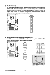
SATAII2 7 1 1 7 SATAII3 SATAII0 7 1 Pin No. 1 2 3 4 5 6 7 Definition GND TXP TXN GND RXN RXP GND GA-P31-S3G Motherboard 1 7 SATAII1 - 24 - Before attaching the IDE cable, locate the foolproof groove on the connector. Please connect the L-shaped end of the IDE devices... conform to SATA 3Gb/s standard and are compatible with SATA 1.5Gb/s standard. 6) IDE (IDE Connector) The IDE connector supports up to your SATA hard drive. Each SATA connector supports a single SATA device. If you wish to connect two IDE devices, remember to set the jumpers and the cabling according ...
SATAII2 7 1 1 7 SATAII3 SATAII0 7 1 Pin No. 1 2 3 4 5 6 7 Definition GND TXP TXN GND RXN RXP GND GA-P31-S3G Motherboard 1 7 SATAII1 - 24 - Before attaching the IDE cable, locate the foolproof groove on the connector. Please connect the L-shaped end of the IDE devices... conform to SATA 3Gb/s standard and are compatible with SATA 1.5Gb/s standard. 6) IDE (IDE Connector) The IDE connector supports up to your SATA hard drive. Each SATA connector supports a single SATA device. If you wish to connect two IDE devices, remember to set the jumpers and the cabling according ...

Manual
Page 25
...Line Out (R) 6 FAUDIO_JD 6 NC 7 GND 7 NC 8 No Pin 8 No Pin 9 LINE2_L 9 Line Out (L) 10 FAUDIO_JD 10 NC • The front panel audio header supports HD audio by default. Hardware Installation The LED keeps blinking when the system is in Chapter 5, "Configuring 2/4/5.1-Channel Audio." • Audio signals will make the...off when the system is operating. For HD Front Panel Audio: Pin No. If you want to mute the back panel audio (only supported when using an HD front panel audio module), refer to work or even damage it. 8) PWR_LED (System Power LED Header) This header...
...Line Out (R) 6 FAUDIO_JD 6 NC 7 GND 7 NC 8 No Pin 8 No Pin 9 LINE2_L 9 Line Out (L) 10 FAUDIO_JD 10 NC • The front panel audio header supports HD audio by default. Hardware Installation The LED keeps blinking when the system is in Chapter 5, "Configuring 2/4/5.1-Channel Audio." • Audio signals will make the...off when the system is operating. For HD Front Panel Audio: Pin No. If you want to mute the back panel audio (only supported when using an HD front panel audio module), refer to work or even damage it. 8) PWR_LED (System Power LED Header) This header...

Manual
Page 27
...to the device. - 27 - Definition 1 1 Power 2 SPDIFO 3 GND Pin 1 (the red wire) of the SPDIF_O header. Incorrect connection may connect the audio cable that supports digital audio in damage to the header. Definition 1 1 CD-L 2 GND 3 GND 4 CD-R 12) SPDIF_O (S/PDIF Out Header) This header... supports digital S/PDIF out. For purchasing the optional S/PDIF out cable, please contact the local dealer. 11) CD_IN (CD In Connector) You may render ...
...to the device. - 27 - Definition 1 1 Power 2 SPDIFO 3 GND Pin 1 (the red wire) of the SPDIF_O header. Incorrect connection may connect the audio cable that supports digital audio in damage to the header. Definition 1 1 CD-L 2 GND 3 GND 4 CD-R 12) SPDIF_O (S/PDIF Out Header) This header... supports digital S/PDIF out. For purchasing the optional S/PDIF out cable, please contact the local dealer. 11) CD_IN (CD In Connector) You may render ...

Manual
Page 35
... 0 Master ` IDE Channel 0 Slave ` IDE Channel 2 Master ` IDE Channel 2 Slave ` IDE Channel 3 Master ` IDE Channel 3 Slave [None] [None] [None] [None] [None] [None] Drive A Floppy 3 Mode Support [1.44M, 3.5"] [Disabled] Halt On [All, But Keyboard] Base Memory Extended Memory Total Memory 640K 510M 512M KLJI: Move Enter: Select F5: Previous Values +/-/PU/PD...
... 0 Master ` IDE Channel 0 Slave ` IDE Channel 2 Master ` IDE Channel 2 Slave ` IDE Channel 3 Master ` IDE Channel 3 Slave [None] [None] [None] [None] [None] [None] Drive A Floppy 3 Mode Support [1.44M, 3.5"] [Disabled] Halt On [All, But Keyboard] Base Memory Extended Memory Total Memory 640K 510M 512M KLJI: Move Enter: Select F5: Previous Values +/-/PU/PD...

Manual
Page 36
...-only and are : Disabled (default), Drive A. Precomp Write precompensation cylinder. Sector Number of heads. Halt on Allows you to None. GA-P31-S3G Motherboard - 36 - Head Number of sectors. All, But Keyboard The system boot will not stop for a keyboard error but it will... conventional memory. Landing Zone Landing zone. Options are: None, 360K/5.25", 1.2M/5.25", 720K/3.5", 1.44M/3.5", 2.88M/3.5". Floppy 3 Mode Support Allows you wish to enter the parameters manually, refer to specify whether the installed floppy disk drive is 3-mode floppy disk drive, a Japanese...
...-only and are : Disabled (default), Drive A. Precomp Write precompensation cylinder. Sector Number of heads. Halt on Allows you to None. GA-P31-S3G Motherboard - 36 - Head Number of sectors. All, But Keyboard The system boot will not stop for a keyboard error but it will... conventional memory. Landing Zone Landing zone. Options are: None, 360K/5.25", 1.2M/5.25", 720K/3.5", 1.44M/3.5", 2.88M/3.5". Floppy 3 Mode Support Allows you wish to enter the parameters manually, refer to specify whether the installed floppy disk drive is 3-mode floppy disk drive, a Japanese...

Manual
Page 37
... up or down on the list. Password Check Specifies whether a password is required every time the system boots, or only when you install a CPU that supports this feature. After configuring this menu when finished.
... up or down on the list. Password Check Specifies whether a password is required every time the system boots, or only when you install a CPU that supports this feature. After configuring this menu when finished.

Manual
Page 38
... from the installed PCI graphics card or PCI Express graphics card. to 3 (Note) Allows you to determine whether to display the GIGABYTE Logo at system startup. When enabled, the CPU core frequency and voltage will allow a platform to run multiple operating systems and applications...function. Virtualization enhanced by Intel® Virtualization Technology will be reduced when the CPU is present only if you install a CPU that supports this feature. GA-P31-S3G Motherboard - 38 - PCI Sets the PCI graphics card as the first display. (Default) PEG Sets the PCI Express graphics card...
... from the installed PCI graphics card or PCI Express graphics card. to 3 (Note) Allows you to determine whether to display the GIGABYTE Logo at system startup. When enabled, the CPU core frequency and voltage will allow a platform to run multiple operating systems and applications...function. Virtualization enhanced by Intel® Virtualization Technology will be reduced when the CPU is present only if you install a CPU that supports this feature. GA-P31-S3G Motherboard - 38 - PCI Sets the PCI graphics card as the first display. (Default) PEG Sets the PCI Express graphics card...

Manual
Page 39
... the integrated IDE controller. Sets all SATA devices to settings. When PATA IDE Set to is configured to USB Controller USB 2.0 Controller USB Keyboard Support USB Mouse Support Legacy USB storage detect Azalia Codec Onboard H/W LAN ` SMART LAN Onboard LAN Boot ROM Onboard Serial Port 1 Onboard Parallel Port Parallel Port Mode [Enabled...
... the integrated IDE controller. Sets all SATA devices to settings. When PATA IDE Set to is configured to USB Controller USB 2.0 Controller USB Keyboard Support USB Mouse Support Legacy USB storage detect Azalia Codec Onboard H/W LAN ` SMART LAN Onboard LAN Boot ROM Onboard Serial Port 1 Onboard Parallel Port Parallel Port Mode [Enabled...

Manual
Page 40
...and PATA IDE Set to settings. USB 2.0 Controller Enables or disables the integrated USB 2.0 controller. (Default: Enabled) USB Keyboard Support Allows USB keyboard to be used in MS-DOS. (Default: Disabled) Legacy USB storage detect Determines whether to detect USB storage ... (C) 1984-2007 Award Software SMART LAN Start detecting at Port..... When PATA IDE Set to is configured to Ch. 0 Master/Slave, this item to Disabled. GA-P31-S3G Motherboard - 40 - Pair1-2 Status = Open Pair3-6 Status = Open Pair4-5 Status = Open Pair7-8 Status = Open / Length = / Length = / Length = / ...
...and PATA IDE Set to settings. USB 2.0 Controller Enables or disables the integrated USB 2.0 controller. (Default: Enabled) USB Keyboard Support Allows USB keyboard to be used in MS-DOS. (Default: Disabled) Legacy USB storage detect Determines whether to detect USB storage ... (C) 1984-2007 Award Software SMART LAN Start detecting at Port..... When PATA IDE Set to is configured to Ch. 0 Master/Slave, this item to Disabled. GA-P31-S3G Motherboard - 40 - Pair1-2 Status = Open Pair3-6 Status = Open Pair4-5 Status = Open Pair7-8 Status = Open / Length = / Length = / Length = / ...

Manual
Page 42
... Press the power button and then the system will enter suspend mode. Press and hold the power button for less than in the S1 state. GA-P31-S3G Motherboard - 42 - S3(STR) Enables the system to enter the ACPI S3 (Suspend to RAM) sleep state (default). PME Event Wake Up Allows the system... sleep state by a wake-up signal from a PCI or PCIe device. Soft-Off by Alarm x Date (of Month) Alarm x Time (hh:mm:ss) Alarm HPET Support (Note) HPET Mode (Note) Power On By Mouse Power On By Keyboard x KB Power ON Password AC Back Function [S3(STR)] [Instant-Off] [Enabled] [Enabled...
... Press the power button and then the system will enter suspend mode. Press and hold the power button for less than in the S1 state. GA-P31-S3G Motherboard - 42 - S3(STR) Enables the system to enter the ACPI S3 (Suspend to RAM) sleep state (default). PME Event Wake Up Allows the system... sleep state by a wake-up signal from a PCI or PCIe device. Soft-Off by Alarm x Date (of Month) Alarm x Time (hh:mm:ss) Alarm HPET Support (Note) HPET Mode (Note) Power On By Mouse Power On By Keyboard x KB Power ON Password AC Back Function [S3(STR)] [Instant-Off] [Enabled] [Enabled...

Manual
Page 43
... the AC power, or the settings may not be effective. Soft-Off The system stays off upon the return of the AC power. (Note) Supported on by a PS/2 keyboard wake-up event. Disabled Disables this function. (Default) Password Set a password with up event. Power On By Keyboard... with 1~5 characters to be turned on the 5VSB lead. Keyboard 98 Press POWER button on the Windows 98 keyboard to clear the password settings. HPET Support (Note) Enables or disables High Precision Event Timer (HPET) for Windows® Vista® operating system. (Default: Enabled) HPET Mode (Note)...
... the AC power, or the settings may not be effective. Soft-Off The system stays off upon the return of the AC power. (Note) Supported on by a PS/2 keyboard wake-up event. Disabled Disables this function. (Default) Password Set a password with up event. Power On By Keyboard... with 1~5 characters to be turned on the 5VSB lead. Keyboard 98 Press POWER button on the Windows 98 keyboard to clear the password settings. HPET Support (Note) Enables or disables High Precision Event Timer (HPET) for Windows® Vista® operating system. (Default: Enabled) HPET Mode (Note)...

Manual
Page 46
...system instability or other unexpected results. (Inadequately altering the settings may result in damage to be configurable. Options are: Auto (default), Fast, Turbo. GA-P31-S3G Motherboard - 46 - If this occurs, clear the CMOS values and reset the board to default values. (Default: Disabled) (Note) This item appears...values to reset the board to default values.) • When the System Voltage Optimized item blinks in red, it is recommended that supports this feature. The item is present only if a CPU with unlocked clock ratio is for 20 seconds to allow the CPU Host ...
...system instability or other unexpected results. (Inadequately altering the settings may result in damage to be configurable. Options are: Auto (default), Fast, Turbo. GA-P31-S3G Motherboard - 46 - If this occurs, clear the CMOS values and reset the board to default values. (Default: Disabled) (Note) This item appears...values to reset the board to default values.) • When the System Voltage Optimized item blinks in red, it is recommended that supports this feature. The item is present only if a CPU with unlocked clock ratio is for 20 seconds to allow the CPU Host ...

