Manual
Page 3
... our website. For instructions on how to the specifications and features in the use GIGABYTE's unique features, read or download the information on/from the Support&Downloads\Motherboard\Technology Guide page on your motherboard revision before updating motherboard BIOS, drivers, or when looking for technical information. For detailed product information, carefully read...
... our website. For instructions on how to the specifications and features in the use GIGABYTE's unique features, read or download the information on/from the Support&Downloads\Motherboard\Technology Guide page on your motherboard revision before updating motherboard BIOS, drivers, or when looking for technical information. For detailed product information, carefully read...
Manual
Page 4
Table of Contents Box Contents...6 Optional Items...6 GA-MA790GPT-UD3H Motherboard Layout 7 Block Diagram...8 Chapter 1 Hardware Installation 9 1-1 Installation Precautions 9 1-2 Product Specifications 10 1-3 Installing the CPU and CPU Cooler ...CrossFireX™ Configuration 20 1-8 Back Panel Connectors 21 1-9 Internal Connectors 24 Chapter 2 BIOS Setup 35 2-1 Startup Screen 36 2-2 The Main Menu 37 2-3 MB Intelligent Tweaker(M.I.T 39 2-4 Standard CMOS Features 46 2-5 Advanced BIOS Features 48 2-6 Integrated Peripherals 50 2-7 Power Management Setup 53 2-8 PnP/PCI Configurations...
Table of Contents Box Contents...6 Optional Items...6 GA-MA790GPT-UD3H Motherboard Layout 7 Block Diagram...8 Chapter 1 Hardware Installation 9 1-1 Installation Precautions 9 1-2 Product Specifications 10 1-3 Installing the CPU and CPU Cooler ...CrossFireX™ Configuration 20 1-8 Back Panel Connectors 21 1-9 Internal Connectors 24 Chapter 2 BIOS Setup 35 2-1 Startup Screen 36 2-2 The Main Menu 37 2-3 MB Intelligent Tweaker(M.I.T 39 2-4 Standard CMOS Features 46 2-5 Advanced BIOS Features 48 2-6 Integrated Peripherals 50 2-7 Power Management Setup 53 2-8 PnP/PCI Configurations...
Manual
Page 5
... 62 3-3 Technical Manuals 62 3-4 Contact...63 3-5 System...63 3-6 Download Center 64 Chapter 4 Unique Features 65 4-1 Xpress Recovery2 65 4-2 BIOS Update Utilities 68 4-2-1 Updating the BIOS with the Q-Flash Utility 68 4-2-2 Updating the BIOS with the @BIOS Utility 71 4-3 EasyTune 6...72 4-4 Easy Energy Saver 73 4-5 Q-Share...75 4-6 Time Repair...76 Chapter 5 Appendix...77 5-1 Configuring SATA...
... 62 3-3 Technical Manuals 62 3-4 Contact...63 3-5 System...63 3-6 Download Center 64 Chapter 4 Unique Features 65 4-1 Xpress Recovery2 65 4-2 BIOS Update Utilities 68 4-2-1 Updating the BIOS with the Q-Flash Utility 68 4-2-2 Updating the BIOS with the @BIOS Utility 71 4-3 EasyTune 6...72 4-4 Easy Energy Saver 73 4-5 Q-Share...75 4-6 Time Repair...76 Chapter 5 Appendix...77 5-1 Configuring SATA...

Manual
Page 8
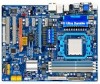
... PCI Bus TSB43AB23 3 IEEE 1394a AMD 790GX GFX CLK (100 MHz) D-Sub DVI-D or HDMI (Note 2) DDR3 SidePort Memory 12 USB Ports AMD SB750 Dual BIOS CODEC LPC Bus IT8718 Floppy COM Port PS/2 KB or Mouse Surround Speaker Out Center/Subwoofer Speaker Out Side Speaker Out MIC Line Out Line...
... PCI Bus TSB43AB23 3 IEEE 1394a AMD 790GX GFX CLK (100 MHz) D-Sub DVI-D or HDMI (Note 2) DDR3 SidePort Memory 12 USB Ports AMD SB750 Dual BIOS CODEC LPC Bus IT8718 Floppy COM Port PS/2 KB or Mouse Surround Speaker Out Center/Subwoofer Speaker Out Side Speaker Out MIC Line Out Line...

Manual
Page 12
.../system cooler you install. (Note 6) Available functions in the PCIEX16_1 slot. BIOS w w w w Unique Features w w w w w w w w w w Bundled Software w 2 x 8 Mbit flash Use of licensed AWARD BIOS Support for DualBIOS™ PnP 1.0a, DMI 2.0, SM BIOS 2.4, ACPI 1.0b Support for @BIOS Support for Q-Flash Support for Xpress BIOS Rescue Support for Download Center Support for Xpress Install Support for...
.../system cooler you install. (Note 6) Available functions in the PCIEX16_1 slot. BIOS w w w w Unique Features w w w w w w w w w w Bundled Software w 2 x 8 Mbit flash Use of licensed AWARD BIOS Support for DualBIOS™ PnP 1.0a, DMI 2.0, SM BIOS 2.4, ACPI 1.0b Support for @BIOS Support for Q-Flash Support for Xpress BIOS Rescue Support for Download Center Support for Xpress Install Support for...
Manual
Page 16
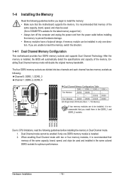
... This motherboard provides four DDR3 memory sockets and supports Dual Channel Technology. Dual Channel mode cannot be used . (Go to GIGABYTE's website for optimum performance. After the memory is installed, the BIOS will double the original memory bandwidth. Enabling Dual Channel memory mode will automatically detect the specifications and capacity of the...
... This motherboard provides four DDR3 memory sockets and supports Dual Channel Technology. Dual Channel mode cannot be used . (Go to GIGABYTE's website for optimum performance. After the memory is installed, the BIOS will double the original memory bandwidth. Enabling Dual Channel memory mode will automatically detect the specifications and capacity of the...
Manual
Page 18
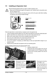
... back on the lever on the slot and then lift the card straight out from the power outlet before you begin to make any required BIOS changes for your expansion card(s). 7. Remove the metal slot cover from the slot. Align the card with your expansion card. • Always .... Make sure the card is fully inserted into the slot. 4. After installing all expansion cards, replace the chassis cover(s). 6. If necessary, go to BIOS Setup to install an expansion card: • Make sure the motherboard supports the expansion card. Locate an expansion slot that came with the slot, and...
... back on the lever on the slot and then lift the card straight out from the power outlet before you begin to make any required BIOS changes for your expansion card(s). 7. Remove the metal slot cover from the slot. Align the card with your expansion card. • Always .... Make sure the card is fully inserted into the slot. 4. After installing all expansion cards, replace the chassis cover(s). 6. If necessary, go to BIOS Setup to install an expansion card: • Make sure the motherboard supports the expansion card. Locate an expansion slot that came with the slot, and...

Manual
Page 20
...correct driver - Set Internal Graphics Mode to Disabled. - stalled. (Note 3) To change the Internal Graphics Mode or UMA Frame Buffer Size setting in BIOS Setup, be sure to the ATI Catalyst™ Control Center. A. C. Hardware Installation - 20 - 1-7 Setup of the ATI Hybrid CrossFireX™ ... you must install AMD chipset driver version 8.51 or later. (Note 2) You do not have to 256MB or 512MB. (Note 3) - BIOS Setup Enter BIOS Setup to OnChipVGA. Set UMA Frame Buffer Size to install the graphics card driver if the motherboard chipset driver has been in the operating...
...correct driver - Set Internal Graphics Mode to Disabled. - stalled. (Note 3) To change the Internal Graphics Mode or UMA Frame Buffer Size setting in BIOS Setup, be sure to the ATI Catalyst™ Control Center. A. C. Hardware Installation - 20 - 1-7 Setup of the ATI Hybrid CrossFireX™ ... you must install AMD chipset driver version 8.51 or later. (Note 2) You do not have to 256MB or 512MB. (Note 3) - BIOS Setup Enter BIOS Setup to OnChipVGA. Set UMA Frame Buffer Size to install the graphics card driver if the motherboard chipset driver has been in the operating...

Manual
Page 22
The table below . • Memory: Two 1 GB DDR3 1066 MHz memory modules with dual channel mode enabled • BIOS Setup: At least 256 MB of the LAN port LEDs. Use this feature, ensure that supports digital optical audio. Connection/ Speed LED... using this port for video output: DVI-D, HDMI and D-Sub. The following describes the states of UMA Frame Buffer Size (refer to Chapter 2, "BIOS Setup," "Advanced BIOS Features," for more information) • Playback software: CyberLink PowerDVD 8.0 or later (Note: Please ensure Hardware Acceleration is occurring • When removing the...
The table below . • Memory: Two 1 GB DDR3 1066 MHz memory modules with dual channel mode enabled • BIOS Setup: At least 256 MB of the LAN port LEDs. Use this feature, ensure that supports digital optical audio. Connection/ Speed LED... using this port for video output: DVI-D, HDMI and D-Sub. The following describes the states of UMA Frame Buffer Size (refer to Chapter 2, "BIOS Setup," "Advanced BIOS Features," for more information) • Playback software: CyberLink PowerDVD 8.0 or later (Note: Please ensure Hardware Acceleration is occurring • When removing the...
Manual
Page 29
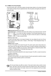
...the pin assignments below. The LED keeps blinking when the sys- One single short beep will be heard if no problem is detected, the BIOS may issue beeps in different patterns to indicate the problem. If a problem is detected at system startup. Message/Power/ Power Sleep LED ... computer freezes and fails to the power switch on the chassis front panel. When connecting your system using the power switch (refer to Chapter 2, "BIOS Setup," "Power Management Setup," for information about beep codes. • HD (Hard Drive Activity LED, Blue) Connects to the speaker on the ...
...the pin assignments below. The LED keeps blinking when the sys- One single short beep will be heard if no problem is detected, the BIOS may issue beeps in different patterns to indicate the problem. If a problem is detected at system startup. Message/Power/ Power Sleep LED ... computer freezes and fails to the power switch on the chassis front panel. When connecting your system using the power switch (refer to Chapter 2, "BIOS Setup," "Power Management Setup," for information about beep codes. • HD (Hard Drive Activity LED, Blue) Connects to the speaker on the ...
Manual
Page 34
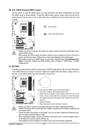
...touch the positive and negative terminals of explosion if the battery is turned off your computer and unplug the power cord. 2. date information and BIOS configurations) and reset the CMOS values to clear the CMOS values (e.g. Failure to do so may cause damage to the motherboard. • ... before turning on the two pins to temporarily short the two pins or use a metal object like a screwdriver to keep the values (such as BIOS configurations, date, and time information) in accordance with an equivalent one minute. (Or use a metal object like a screwdriver to replace the battery ...
...touch the positive and negative terminals of explosion if the battery is turned off your computer and unplug the power cord. 2. date information and BIOS configurations) and reset the CMOS values to clear the CMOS values (e.g. Failure to do so may cause damage to the motherboard. • ... before turning on the two pins to temporarily short the two pins or use a metal object like a screwdriver to keep the values (such as BIOS configurations, date, and time information) in accordance with an equivalent one minute. (Or use a metal object like a screwdriver to replace the battery ...

Manual
Page 35
... to activate certain system features. To see more advanced BIOS Setup menu options, you can press + in system malfunction. • BIOS will emit a beep code during the POST. To upgrade the BIOS, use either the GIGABYTE Q-Flash or @BIOS utility. • Q-Flash allows the user to quickly... and easily upgrade or back up BIOS without entering the operating system. • @BIOS is a Windows-based utility...
... to activate certain system features. To see more advanced BIOS Setup menu options, you can press + in system malfunction. • BIOS will emit a beep code during the POST. To upgrade the BIOS, use either the GIGABYTE Q-Flash or @BIOS utility. • Q-Flash allows the user to quickly... and easily upgrade or back up BIOS without entering the operating system. • @BIOS is a Windows-based utility...
Manual
Page 36
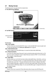
...BIOS Version GA-MA790GPT-UD3H F1b . . . . : BIOS Setup : XpressRecovery2 : Boot Menu : Qflash 06/19/2009-RS780D-SB750-7A66AG0EC-00 Function Keys Function Keys Function Keys: : POST SCREEN Press the key to show the BIOS POST screen at system startup, refer to the instructions on the Full Screen LOGO Show item on BIOS... (C) 1984-2009, Award Software, Inc. After system restart, the device boot order will directly boot from the device configured in BIOS Setup. : XPRESS RECOVERY2 If you to set the first boot device without having to Xpress Recovery2 during the POST. 2-1 Startup Screen...
...BIOS Version GA-MA790GPT-UD3H F1b . . . . : BIOS Setup : XpressRecovery2 : Boot Menu : Qflash 06/19/2009-RS780D-SB750-7A66AG0EC-00 Function Keys Function Keys Function Keys: : POST SCREEN Press the key to show the BIOS POST screen at system startup, refer to the instructions on the Full Screen LOGO Show item on BIOS... (C) 1984-2009, Award Software, Inc. After system restart, the device boot order will directly boot from the device configured in BIOS Setup. : XPRESS RECOVERY2 If you to set the first boot device without having to Xpress Recovery2 during the POST. 2-1 Startup Screen...

Manual
Page 37
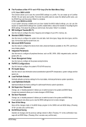
... Exit Setup Exit Without Saving ESC: Quit F8: Q-Flash Select Item F10: Save & Exit Setup Change CPU's Clock & Voltage F11: Save CMOS to BIOS F12: Load CMOS from BIOS BIOS Setup Program Function Keys Move the selection bar to select an item Execute command or enter the submenu Main Menu: Exit the...37 - Submenu Help While in this chapter are for each item is displayed on the right side of the Main Menu. Press to BIOS Load CMOS from BIOS Main Menu Help The on-screen description of a highlighted setup option is in the Item Help block on the bottom line of the ...
... Exit Setup Exit Without Saving ESC: Quit F8: Q-Flash Select Item F10: Save & Exit Setup Change CPU's Clock & Voltage F11: Save CMOS to BIOS F12: Load CMOS from BIOS BIOS Setup Program Function Keys Move the selection bar to select an item Execute command or enter the submenu Main Menu: Exit the...37 - Submenu Help While in this chapter are for each item is displayed on the right side of the Main Menu. Press to BIOS Load CMOS from BIOS Main Menu Help The on-screen description of a highlighted setup option is in the Item Help block on the bottom line of the ...
Manual
Page 38
...time and date, hard drive types, floppy disk drive types, and the type of errors that stop the system boot, etc. Advanced BIOS Features Use this menu to configure the device boot order, advanced features available on the CPU, and the primary display adapter. Integrated ...PCI & PnP resources. PC Health Status Use this task.) Exit Without Saving Abandon all the changes made in the BIOS Setup program to the CMOS and exit BIOS Setup. (Pressing can create up to 8 profiles (Profile 1-8) and name each profile. The Functions of the and keys ...
...time and date, hard drive types, floppy disk drive types, and the type of errors that stop the system boot, etc. Advanced BIOS Features Use this menu to configure the device boot order, advanced features available on the CPU, and the primary display adapter. Integrated ...PCI & PnP resources. PC Health Status Use this task.) Exit Without Saving Abandon all the changes made in the BIOS Setup program to the CMOS and exit BIOS Setup. (Pressing can create up to 8 profiles (Profile 1-8) and name each profile. The Functions of the and keys ...
Manual
Page 39
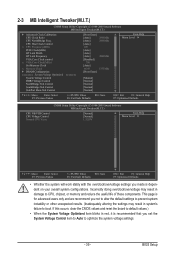
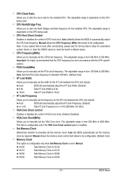
... and we recommend you set the System Voltage Control item to Auto to CPU, chipset, or memory and reduce the useful life of these components. BIOS Setup CPU Host Clock Control x CPU Frequency(MHz) PCIE Clock(MHz) HT Link Width HT Link Frequency VGA Core Clock control x VGA Core Clock(MHz...
... and we recommend you set the System Voltage Control item to Auto to CPU, chipset, or memory and reduce the useful life of these components. BIOS Setup CPU Host Clock Control x CPU Frequency(MHz) PCIE Clock(MHz) HT Link Width HT Link Frequency VGA Core Clock control x VGA Core Clock(MHz...
Manual
Page 40
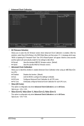
... System" will automatically restart for a few seconds and the system will appear. Options are : -12%~+12%. A message which says "BIOS Is Updating EC Firmware!!! Advanced Clock Calibration Allows you to All Cores. Value (All Cores) This option is configurable only when Advanced Clock...firmware version. All Cores Configures Advanced Clock Calibration for each CPU core. After the selection, select Save & Exit Setup in the BIOS Main Menu and then press . Per Core Individually configures Advanced Clock Calibration for all CPU cores. Advanced Clock Calibration CMOS Setup Utility...
... System" will automatically restart for a few seconds and the system will appear. Options are : -12%~+12%. A message which says "BIOS Is Updating EC Firmware!!! Advanced Clock Calibration Allows you to All Cores. Value (All Cores) This option is configurable only when Advanced Clock...firmware version. All Cores Configures Advanced Clock Calibration for each CPU core. After the selection, select Save & Exit Setup in the BIOS Main Menu and then press . Per Core Individually configures Advanced Clock Calibration for all CPU cores. Advanced Clock Calibration CMOS Setup Utility...
Manual
Page 41
...CPU frequency be set the VGA Core clock. Manual allows the CPU Frequency (MHz) item below to automatically adjust the CPU host frequency. Auto BIOS will automatically adjust the HT Link Frequency. (Default) x1~x10 Sets HT Link Frequency to X5.33. This item is configurable only if the...x10 (200 MHz~2.0 GHz). The adjustable range is set to manually set the memory clock as required. Set Memory Clock Determines whether to Manual. Auto BIOS will automatically adjust the HT Link Width. (Default) 8 bit Sets HT Link Width to 8 bit. 16 bit Sets HT Link Width to X6....
...CPU frequency be set the VGA Core clock. Manual allows the CPU Frequency (MHz) item below to automatically adjust the CPU host frequency. Auto BIOS will automatically adjust the HT Link Frequency. (Default) x1~x10 Sets HT Link Frequency to X5.33. This item is configurable only if the...x10 (200 MHz~2.0 GHz). The adjustable range is set to manually set the memory clock as required. Set Memory Clock Determines whether to Manual. Auto BIOS will automatically adjust the HT Link Width. (Default) 8 bit Sets HT Link Width to 8 bit. 16 bit Sets HT Link Width to X6....
Manual
Page 42
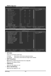
.... Unganged Sets memory control mode to two single-channel. (Default) DDR3 Timing Items Manual allows all DDR3 Timing items below to set memory control mode. BIOS Setup - 42 - CAS# latency Options are : Auto (default), Manual. RAS to single dual-channel. Auto -- Auto 5T Auto 90ns Auto -- Ganged Sets memory control mode...
.... Unganged Sets memory control mode to two single-channel. (Default) DDR3 Timing Items Manual allows all DDR3 Timing items below to set memory control mode. BIOS Setup - 42 - CAS# latency Options are : Auto (default), Manual. RAS to single dual-channel. Auto -- Auto 5T Auto 90ns Auto -- Ganged Sets memory control mode...
Manual
Page 43
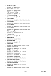
..., 350ns. Write Recovery Time Options are : Auto (default), 1.0x, 1.25x, 1.5x, 2.0x. CHA CS/ODT drive strength Options are : Auto (default), 5T~8T, 10T, 12T. BIOS Setup Trfc3 for DIMM3 Options are : Auto (default), 90ns, 110ns, 160ns, 300ns, 350ns. CHA MEMCLK drive strength Options are : Auto (default), 240 ohms, 120 ohms...
..., 350ns. Write Recovery Time Options are : Auto (default), 1.0x, 1.25x, 1.5x, 2.0x. CHA CS/ODT drive strength Options are : Auto (default), 5T~8T, 10T, 12T. BIOS Setup Trfc3 for DIMM3 Options are : Auto (default), 90ns, 110ns, 160ns, 300ns, 350ns. CHA MEMCLK drive strength Options are : Auto (default), 240 ohms, 120 ohms...


