Manual
Page 4
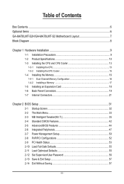
Table of Contents Box Contents...6 Optional Items...6 GA-MA78LMT-S2H/GA-MA78LMT-S2 Motherboard Layout 7 Block Diagram...8 Chapter 1 Hardware Installation 9 1-1 Installation Precautions 9 1-2 Product Specifications 10 1-3 Installing the CPU and CPU Cooler 13 1-3-1 Installing the CPU 13 1-3-2 Installing the CPU Cooler 15 1-4 Installing the Memory 16 1-4-1 Dual Channel Memory Configuration 16 1-4-2 Installing a Memory 17 1-5 Installing an Expansion Card 18 1-6 Back...
Table of Contents Box Contents...6 Optional Items...6 GA-MA78LMT-S2H/GA-MA78LMT-S2 Motherboard Layout 7 Block Diagram...8 Chapter 1 Hardware Installation 9 1-1 Installation Precautions 9 1-2 Product Specifications 10 1-3 Installing the CPU and CPU Cooler 13 1-3-1 Installing the CPU 13 1-3-2 Installing the CPU Cooler 15 1-4 Installing the Memory 16 1-4-1 Dual Channel Memory Configuration 16 1-4-2 Installing a Memory 17 1-5 Installing an Expansion Card 18 1-6 Back...
Manual
Page 8
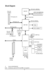
Block Diagram PCIe CLK (100 MHz) 1 PCI Express x16 AM3 CPU CPU CLK+/- (200 MHz) DDR3 1333/1066/800 MHz Dual Channel Memory Hyper Transport Bus PCI Express x16 GFX CLK (100 MHz) PCI Express Bus x1 PCIe CLK (100 MHz) 1 PCI Express x1 RTL8111D RJ45 LAN AMD ... BIOS Floppy COM Port MIC Line Out Line In S/PDIF In S/PDIF Out 2 PCI PS/2 KB or Mouse PCI CLK (33 MHz) j (Note) Only for GA-MA78LM-S2H Simultaneous output for DVI-D and HDMI is not supported. - 8 -
Block Diagram PCIe CLK (100 MHz) 1 PCI Express x16 AM3 CPU CPU CLK+/- (200 MHz) DDR3 1333/1066/800 MHz Dual Channel Memory Hyper Transport Bus PCI Express x16 GFX CLK (100 MHz) PCI Express Bus x1 PCIe CLK (100 MHz) 1 PCI Express x1 RTL8111D RJ45 LAN AMD ... BIOS Floppy COM Port MIC Line Out Line In S/PDIF In S/PDIF Out 2 PCI PS/2 KB or Mouse PCI CLK (33 MHz) j (Note) Only for GA-MA78LM-S2H Simultaneous output for DVI-D and HDMI is not supported. - 8 -
Manual
Page 9
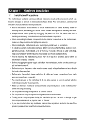
.... • Turning on the computer power during the installation process can become damaged as a result of electrostatic discharge (ESD). ponents such as a motherboard, CPU or memory. Prior to installation, carefully read the user's manual and follow these procedures: • Prior to installation, do not have an ESD wrist strap, keep your...
.... • Turning on the computer power during the installation process can become damaged as a result of electrostatic discharge (ESD). ponents such as a motherboard, CPU or memory. Prior to installation, carefully read the user's manual and follow these procedures: • Prior to installation, do not have an ESD wrist strap, keep your...
Manual
Page 10
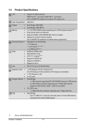
... South Bridge: AMD SB710 2 x 1.5V DDR3 DIMM sockets supporting up to 8 GB of system memory (Note 1) Dual channel memory architecture Support for DDR3 1333/1066/800 MHz memory modules Support for non-ECC memory modules (Go to GIGABYTE's website for the latest memory support list.) Integrated in the North Bridge: - 1 x D-Sub port - 1 x DVI-D port (Note 2) (Note... to 4 SATA 3Gb/s devices - Up to 12 USB 2.0/1.1 ports (8 on the back panel, 4 via the USB brackets connected to the internal USB headers) j Only for GA-MA78LMT-S2H Hardware Installation - 10 -
... South Bridge: AMD SB710 2 x 1.5V DDR3 DIMM sockets supporting up to 8 GB of system memory (Note 1) Dual channel memory architecture Support for DDR3 1333/1066/800 MHz memory modules Support for non-ECC memory modules (Go to GIGABYTE's website for the latest memory support list.) Integrated in the North Bridge: - 1 x D-Sub port - 1 x DVI-D port (Note 2) (Note... to 4 SATA 3Gb/s devices - Up to 12 USB 2.0/1.1 ports (8 on the back panel, 4 via the USB brackets connected to the internal USB headers) j Only for GA-MA78LMT-S2H Hardware Installation - 10 -
Manual
Page 12
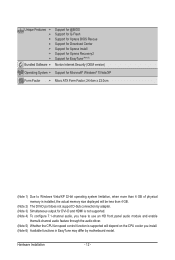
... Form Factor; 24.4cm x 22.0cm (Note 1) Due to Windows Vista/XP 32-bit operating system limitation, when more than 4 GB of physical memory is installed, the actual memory size displayed will be less than 4 GB. (Note 2) The DVI-D port does not support D-Sub connection by adapter. (Note 3) Simultaneous output for DVI...
... Form Factor; 24.4cm x 22.0cm (Note 1) Due to Windows Vista/XP 32-bit operating system limitation, when more than 4 GB of physical memory is installed, the actual memory size displayed will be less than 4 GB. (Note 2) The DVI-D port does not support D-Sub connection by adapter. (Note 3) Simultaneous output for DVI...
Manual
Page 13
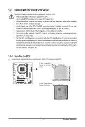
... the computer and unplug the power cord from the power outlet before installing the CPU to your hardware specifications including the CPU, graphics card, memory, hard drive, etc. 1-3-1 Installing the CPU A. If you wish to set beyond the standard specifications, please do so according to prevent ...support list.) • Always turn on the computer if the CPU cooler is not recommended that the motherboard supports the CPU. (Go to GIGABYTE's website for the peripherals. Locate the pin one of the CPU. Hardware Installation It is not installed, otherwise overheating and dam- 1-3 ...
... the computer and unplug the power cord from the power outlet before installing the CPU to your hardware specifications including the CPU, graphics card, memory, hard drive, etc. 1-3-1 Installing the CPU A. If you wish to set beyond the standard specifications, please do so according to prevent ...support list.) • Always turn on the computer if the CPU cooler is not recommended that the motherboard supports the CPU. (Go to GIGABYTE's website for the peripherals. Locate the pin one of the CPU. Hardware Installation It is not installed, otherwise overheating and dam- 1-3 ...
Manual
Page 16
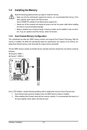
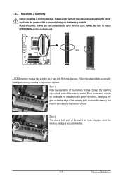
...to prevent hardware damage. • Memory modules have a foolproof design. Dual Channel mode cannot be used . After the memory is recommended that memory of the same capacity, brand, speed, and chips be used . (Go to GIGABYTE's website for the latest memory support list.) • Always turn... off the computer and unplug the power cord from the power outlet before installing the memory to install the memory: • Make sure that memory of the memory. 1-4 Installing the Memory Read the following ...
...to prevent hardware damage. • Memory modules have a foolproof design. Dual Channel mode cannot be used . After the memory is recommended that memory of the same capacity, brand, speed, and chips be used . (Go to GIGABYTE's website for the latest memory support list.) • Always turn... off the computer and unplug the power cord from the power outlet before installing the memory to install the memory: • Make sure that memory of the memory. 1-4 Installing the Memory Read the following ...
Manual
Page 17
... install DDR3 DIMMs on the left, place your memory modules in the memory sockets. Step 1: Note the orientation of the memory, push down on the socket. Step 2: The clips at both ends of the memory socket. Place the memory module on the memory and insert it can only fit in the picture... not compatible to each other or DDR DIMMs. Be sure to correctly install your fingers on the top edge of the memory module. 1-4-2 Installing a Memory Before installing a memory module, make sure to turn off the computer and unplug the power cord from the power outlet to prevent damage to ...
... install DDR3 DIMMs on the left, place your memory modules in the memory sockets. Step 1: Note the orientation of the memory, push down on the socket. Step 2: The clips at both ends of the memory socket. Place the memory module on the memory and insert it can only fit in the picture... not compatible to each other or DDR DIMMs. Be sure to correctly install your fingers on the top edge of the memory module. 1-4-2 Installing a Memory Before installing a memory module, make sure to turn off the computer and unplug the power cord from the power outlet to prevent damage to ...
Manual
Page 20
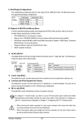
.... Mic In Jack (Pink) The default Mic in jack. The table below . • CPU: AMD Phenom™ X3 processor or above • Memory: Two 1 GB DDR3 1066 MHz memory modules with dual channel mode enabled • BIOS Setup: At least 256 MB of the LAN port LEDs. Use this jack. Microphones must...
.... Mic In Jack (Pink) The default Mic in jack. The table below . • CPU: AMD Phenom™ X3 processor or above • Memory: Two 1 GB DDR3 1066 MHz memory modules with dual channel mode enabled • BIOS Setup: At least 256 MB of the LAN port LEDs. Use this jack. Microphones must...
Manual
Page 34
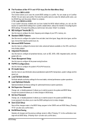
... & Exit Setup Save all changes and the previous settings remain in the BIOS Setup program to load the BIOS settings from BIOS If your CPU, memory, etc. Standard CMOS Features Use this task.) Exit Without Saving Abandon all the changes made in effect. A user password only allows you to...
... & Exit Setup Save all changes and the previous settings remain in the BIOS Setup program to load the BIOS settings from BIOS If your CPU, memory, etc. Standard CMOS Features Use this task.) Exit Without Saving Abandon all the changes made in effect. A user password only allows you to...
Manual
Page 35
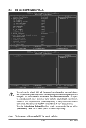
...Ratio CPU NorthBridge Freq.(Note) CPU Host Clock Control x CPU Frequency(MHz) PCIE Clock(MHz) HT Link Width HT Link Frequency Set Memory Clock x Memory Clock } DRAM Configuration ******** System Voltage Optimized ******** System Voltage Control x DDR3 Voltage Control x NorthBridge Volt Control x SouthBridge Volt Control...'s failure to default values.) • When the System Voltage Optimized item blinks in damage to CPU, chipset, or memory and reduce the useful life of these components. This page is for advanced users only and we recommend you install a...
...Ratio CPU NorthBridge Freq.(Note) CPU Host Clock Control x CPU Frequency(MHz) PCIE Clock(MHz) HT Link Width HT Link Frequency Set Memory Clock x Memory Clock } DRAM Configuration ******** System Voltage Optimized ******** System Voltage Control x DDR3 Voltage Control x NorthBridge Volt Control x SouthBridge Volt Control...'s failure to default values.) • When the System Voltage Optimized item blinks in damage to CPU, chipset, or memory and reduce the useful life of these components. This page is for advanced users only and we recommend you install a...
Manual
Page 37
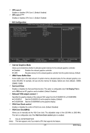
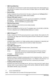
... the Surround View function. The adjustable range is from the system memory. (Default) UMA Frame Buffer Size Frame buffer size is the total amount of system memory allocated solely for the onboard graphics con- j Only for GA-MA78LMT-S2H (Note) This item appears only if you install a CPU... that supports this memory for the onboard graphics controller from 200 MHz to allocate system memory for example, will use only this...
... the Surround View function. The adjustable range is from the system memory. (Default) UMA Frame Buffer Size Frame buffer size is the total amount of system memory allocated solely for the onboard graphics con- j Only for GA-MA78LMT-S2H (Note) This item appears only if you install a CPU... that supports this memory for the onboard graphics controller from 200 MHz to allocate system memory for example, will use only this...
Manual
Page 38
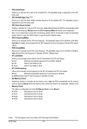
... MHz to default values. The adjustable range is dependent on the CPU being used . Set Memory Clock Determines whether to 500 MHz. Auto lets BIOS automatically set to X4.00. Sets Memory Clock to alter the clock ratio for the installed CPU. CPU Clock Ratio Allows you to ... you to 200 MHz~2.6 GHz. PCIE Clock(MHz) Allows you to X6.66. Manual allows the memory clock control item below to X5.33. X4.00 Sets Memory Clock to Manual. Sets Memory Clock to manually set the PCIe clock frequency. HT Link Frequency Allows you to alter the North Bridge...
... MHz to default values. The adjustable range is dependent on the CPU being used . Set Memory Clock Determines whether to 500 MHz. Auto lets BIOS automatically set to X4.00. Sets Memory Clock to alter the clock ratio for the installed CPU. CPU Clock Ratio Allows you to ... you to 200 MHz~2.6 GHz. PCIE Clock(MHz) Allows you to X6.66. Manual allows the memory clock control item below to X5.33. X4.00 Sets Memory Clock to Manual. Sets Memory Clock to manually set the PCIe clock frequency. HT Link Frequency Allows you to alter the North Bridge...
Manual
Page 39
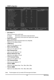
... Minimum RAS Active Time Options are: Auto (default), 15T~30T. 1T/2T Command Timing Options are : Auto (default), Manual. Unganged Sets memory control mode to two single-channel. (Default) DDR3 Timing Items Manual allows all DDR3 Timing items below to single dual-channel. Row Precharge Time ...Options are : Auto (default), 5T~12T. Ganged Sets memory control mode to be configurable. RAS to set memory control mode. Trfc0 for DIMM2 Options are : Auto (default), 90ns, 110ns, 160ns, 300ns, 350ns. CAS# latency Options...
... Minimum RAS Active Time Options are: Auto (default), 15T~30T. 1T/2T Command Timing Options are : Auto (default), Manual. Unganged Sets memory control mode to two single-channel. (Default) DDR3 Timing Items Manual allows all DDR3 Timing items below to single dual-channel. Row Precharge Time ...Options are : Auto (default), 5T~12T. Ganged Sets memory control mode to be configurable. RAS to set memory control mode. Trfc0 for DIMM2 Options are : Auto (default), 90ns, 110ns, 160ns, 300ns, 350ns. CAS# latency Options...
Manual
Page 40
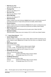
...result in CPU C3 or Alt VID mode. (Default: Disabled) ******** System Voltage Optimized ******** System Voltage Control Determines whether to set memory voltage. Normal Supplies the South Bridge voltage as required. (Default) +0.100V ~ +0.300V The adjustable range is from +0.100V to...set the system voltages. Enabled allows the system to simultaneously access different banks of the memory to increase memory performance and stability. (Default: Enabled) DQS Training Control Enables or disables memory DQS training each time the system restarts. (Default: Skip DQS) Memclock tri-stating...
...result in CPU C3 or Alt VID mode. (Default: Disabled) ******** System Voltage Optimized ******** System Voltage Control Determines whether to set memory voltage. Normal Supplies the South Bridge voltage as required. (Default) +0.100V ~ +0.300V The adjustable range is from +0.100V to...set the system voltages. Enabled allows the system to simultaneously access different banks of the memory to increase memory performance and stability. (Default: Enabled) DQS Training Control Enables or disables memory DQS training each time the system restarts. (Default: Skip DQS) Memclock tri-stating...

Manual
Page 42
... } IDE Channel 3 Master } IDE Channel 3 Slave [None] [None] [None] [None] [None] [None] Drive A Floppy 3 Mode Support [1.44M, 3.5"] [Disabled] Halt On [All, But Keyboard] Base Memory Extended Memory 640K 1790M Move Enter: Select F5: Previous Values +/-/PU/PD: Value F10: Save F6: Fail-Safe Defaults ESC: Exit F1: General Help F7: Optimized Defaults...
... } IDE Channel 3 Master } IDE Channel 3 Slave [None] [None] [None] [None] [None] [None] Drive A Floppy 3 Mode Support [1.44M, 3.5"] [Disabled] Halt On [All, But Keyboard] Base Memory Extended Memory 640K 1790M Move Enter: Select F5: Previous Values +/-/PU/PD: Value F10: Save F6: Fail-Safe Defaults ESC: Exit F1: General Help F7: Optimized Defaults...
Manual
Page 43
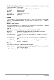
...system boot will not stop . Sector Number of heads. Halt On Allows you wish to enter the parameters manually, refer to None. Memory These fields are read-only and are : None, 360K/5.25", 1.2M/5.25", 720K/3.5", 1.44M/3.5", 2.88M/3.5". Head Number of sectors...Japanese standard floppy disk drive. All, But Keyboard The system boot will be reserved for an error during the POST. Base Memory Also called conventional memory. BIOS Setup The following fields display your system. Options are determined by the BIOS POST. Options are: Disabled (default), Drive...
...system boot will not stop . Sector Number of heads. Halt On Allows you wish to enter the parameters manually, refer to None. Memory These fields are read-only and are : None, 360K/5.25", 1.2M/5.25", 720K/3.5", 1.44M/3.5", 2.88M/3.5". Head Number of sectors...Japanese standard floppy disk drive. All, But Keyboard The system boot will be reserved for an error during the POST. Base Memory Also called conventional memory. BIOS Setup The following fields display your system. Options are determined by the BIOS POST. Options are: Disabled (default), Drive...
Manual
Page 44
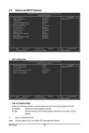
... the onboard graphics controller from the system memory. (Default) j Only for GA-MA78LMT-S2H (Note) This item appears only if you to determine whether to HDD Init Display First [Press Enter] [Disabled] [Disabled] [Enabled] [Auto]...F7: Optimized Defaults Internal Graphics Mode Allows you install a CPU that supports this feature. Capability Away Mode Backup BIOS Image to allocate system memory for the onboard graphics controller. Disabled Disables the onboard graphics controller. 2-5 Advanced BIOS Features CMOS Setup Utility-Copyright (C) 1984-2009 Award Software...
... the onboard graphics controller from the system memory. (Default) j Only for GA-MA78LMT-S2H (Note) This item appears only if you to determine whether to HDD Init Display First [Press Enter] [Disabled] [Disabled] [Enabled] [Auto]...F7: Optimized Defaults Internal Graphics Mode Allows you install a CPU that supports this feature. Capability Away Mode Backup BIOS Image to allocate system memory for the onboard graphics controller. Disabled Disables the onboard graphics controller. 2-5 Advanced BIOS Features CMOS Setup Utility-Copyright (C) 1984-2009 Award Software...
Manual
Page 45
...: Auto (default), 128MB, 256MB, 512MB. The adjustable range is from your computer and its power consumption. (Default) Disabled Disables this memory for example, will be reduced during system halt state to decrease power consumption. (Default: Disabled) Virtualization Virtualization allows a platform to run ...display. Surround View Enables or disables the Surround View function. VGA Core Clock control Enables or disables the control of system memory allocated solely for GA-MA78LMT-S2H (Note) This item appears only if you to manually set to PEG and an ATI graphics card is installed....
...: Auto (default), 128MB, 256MB, 512MB. The adjustable range is from your computer and its power consumption. (Default) Disabled Disables this memory for example, will be reduced during system halt state to decrease power consumption. (Default: Disabled) Virtualization Virtualization allows a platform to run ...display. Surround View Enables or disables the Surround View function. VGA Core Clock control Enables or disables the control of system memory allocated solely for GA-MA78LMT-S2H (Note) This item appears only if you to manually set to PEG and an ATI graphics card is installed....

Manual
Page 51
... time on each day or on automatically. Soft-Off The system stays off upon the return of the AC power. Note: When using this item. Memory The system returns to turn on upon the return of the AC power. (Default) Full-On The system is turned on the system. Power On...
... time on each day or on automatically. Soft-Off The system stays off upon the return of the AC power. Note: When using this item. Memory The system returns to turn on upon the return of the AC power. (Default) Full-On The system is turned on the system. Power On...


