
Manual
Page 1
GA-MA78GM-S2H AM2+/AM2 socket motherboard for AMD PhenomTM FX processor/ AMD PhenomTM processor/ AMD AthlonTM 64 FX processor/ AMD AthlonTM 64 X2 Dual-Core processor/ AMD AthlonTM 64 processor/AMD SempronTM processor User's Manual Rev. 1002 12ME-MA78GMS2H-1002R
GA-MA78GM-S2H AM2+/AM2 socket motherboard for AMD PhenomTM FX processor/ AMD PhenomTM processor/ AMD AthlonTM 64 FX processor/ AMD AthlonTM 64 X2 Dual-Core processor/ AMD AthlonTM 64 processor/AMD SempronTM processor User's Manual Rev. 1002 12ME-MA78GMS2H-1002R

Manual
Page 2
Motherboard GA-MA78GM-S2H Feb. 5, 2008 Motherboard GA-MA78GM-S2H Feb. 5, 2008
Motherboard GA-MA78GM-S2H Feb. 5, 2008 Motherboard GA-MA78GM-S2H Feb. 5, 2008

Manual
Page 3
... TECHNOLOGY CO., LTD as the exclu- sive global distributor of the motherboard is the property of GIGABYTE. Copyright © 2008 GIGA-BYTE TECHNOLOGY CO., LTD. is protected by GIGABYTE without GIGABYTE's prior written permission. Disclaimer Information in any form or by any ... information, check on our website at: http://www.gigabyte.com.tw Identifying Your Motherboard Revision The revision number on how to GIGABYTE UNITED INC. For example, "REV: 1.0" means the revision of GIGABYTE branded motherboards. Documentation Classifications In order to their respective owners. ...
... TECHNOLOGY CO., LTD as the exclu- sive global distributor of the motherboard is the property of GIGABYTE. Copyright © 2008 GIGA-BYTE TECHNOLOGY CO., LTD. is protected by GIGABYTE without GIGABYTE's prior written permission. Disclaimer Information in any form or by any ... information, check on our website at: http://www.gigabyte.com.tw Identifying Your Motherboard Revision The revision number on how to GIGABYTE UNITED INC. For example, "REV: 1.0" means the revision of GIGABYTE branded motherboards. Documentation Classifications In order to their respective owners. ...

Manual
Page 4
Table of Contents Box Contents ...6 OptionalItems ...6 GA-MA78GM-S2H Motherboard Layout 7 Block Diagram ...8 Chapter 1 Hardware Installation 9 1-1 Installation Precautions 9 1-2 Product Specifications 10 1-3 Installing the CPU and CPU Cooler 13 1-3-1 Installing the CPU 13 1-3-2 Installing the CPU ...
Table of Contents Box Contents ...6 OptionalItems ...6 GA-MA78GM-S2H Motherboard Layout 7 Block Diagram ...8 Chapter 1 Hardware Installation 9 1-1 Installation Precautions 9 1-2 Product Specifications 10 1-3 Installing the CPU and CPU Cooler 13 1-3-1 Installing the CPU 13 1-3-2 Installing the CPU ...

Manual
Page 6
... (Part No. 12CF1-1CM001-32R) S/PDIF in and out cable (Part No. 12CR1-1SPINO-11R) LPT port cable (Part No. 12CF1-1LP001-01R) - 6 - Box Contents GA-MA78GM-S2H motherboard Motherboard driver disk User's Manual One IDE cable and one floppy disk drive cable Two SATA 3Gb/s cables I/O Shield • The box contents above are subject...
... (Part No. 12CF1-1CM001-32R) S/PDIF in and out cable (Part No. 12CR1-1SPINO-11R) LPT port cable (Part No. 12CF1-1LP001-01R) - 6 - Box Contents GA-MA78GM-S2H motherboard Motherboard driver disk User's Manual One IDE cable and one floppy disk drive cable Two SATA 3Gb/s cables I/O Shield • The box contents above are subject...

Manual
Page 7
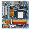
GA-MA78GM-S2H Motherboard Layout DVI-D VGA KB_MS ATX_12V Socket AM2 IT8718 BIOS CI FDD HDMI ATX OPTICAL ESATA 1394 USB CPU_FAN BATTERY LAN USB AUDIO F_AUDIO PCIE_1 RTL 8111C PCIE_16 AMD 780G PCI1 CD_IN CODEC PCI2 GA-MA78GM-S2H SPDIF_IO TPM COM CLR_CMOS LPT DDRII_1 DDRII_2 DDRII_3 DDRII_4 AMD SB700 IDE SATAII4 F_USB1 F_USB2 F_USB3 F_USB4 SATAII2 SATAII3 TSB43AB23 F1_1394 SYS_FAN F_PANEL PWR_LED SATAII0 SATAII1 - 7 -
GA-MA78GM-S2H Motherboard Layout DVI-D VGA KB_MS ATX_12V Socket AM2 IT8718 BIOS CI FDD HDMI ATX OPTICAL ESATA 1394 USB CPU_FAN BATTERY LAN USB AUDIO F_AUDIO PCIE_1 RTL 8111C PCIE_16 AMD 780G PCI1 CD_IN CODEC PCI2 GA-MA78GM-S2H SPDIF_IO TPM COM CLR_CMOS LPT DDRII_1 DDRII_2 DDRII_3 DDRII_4 AMD SB700 IDE SATAII4 F_USB1 F_USB2 F_USB3 F_USB4 SATAII2 SATAII3 TSB43AB23 F1_1394 SYS_FAN F_PANEL PWR_LED SATAII0 SATAII1 - 7 -

Manual
Page 9
...user's manual and follow these procedures: • Prior to installation, do not remove or break motherboard S/N (Serial Number) sticker or warranty sticker provided by unplugging the power cord from the motherboard, make sure the power supply has been turned off. • Before turning on the computer...has been set according to the use of electrostatic discharge (ESD). If you are connected tightly and securely. • When handling the motherboard, avoid touching any metal leads or connectors. • It is best to wear an electrostatic discharge (ESD) wrist strap when handling ...
...user's manual and follow these procedures: • Prior to installation, do not remove or break motherboard S/N (Serial Number) sticker or warranty sticker provided by unplugging the power cord from the motherboard, make sure the power supply has been turned off. • Before turning on the computer...has been set according to the use of electrostatic discharge (ESD). If you are connected tightly and securely. • When handling the motherboard, avoid touching any metal leads or connectors. • It is best to wear an electrostatic discharge (ESD) wrist strap when handling ...

Manual
Page 10
TSB43AB23 chip Up to 2 IEEE 1394a ports (1 on the back panel, 1 via the USB brackets connected to the internal USB headers) GA-MA78GM-S2H Motherboard - 10 - Support for CD In Realtek 8111C chip (10/100/1000 Mbit) 1 x PCI Express x16 slot (The PCI Express x16 slot conforms to PCI Express... up to 16 GB of system memory (Note 1) Dual channel memory architecture Support for DDR2 1066 (Note 2)/800/667 MHz memory modules (Go to GIGABYTE's website for the latest memory support list.) Realtek ALC889A codec High Definition Audio 2/4/5.1/7.1-channel Support for DTS (dts NEO:PC) Support for S/PDIF In...
TSB43AB23 chip Up to 2 IEEE 1394a ports (1 on the back panel, 1 via the USB brackets connected to the internal USB headers) GA-MA78GM-S2H Motherboard - 10 - Support for CD In Realtek 8111C chip (10/100/1000 Mbit) 1 x PCI Express x16 slot (The PCI Express x16 slot conforms to PCI Express... up to 16 GB of system memory (Note 1) Dual channel memory architecture Support for DDR2 1066 (Note 2)/800/667 MHz memory modules (Go to GIGABYTE's website for the latest memory support list.) Realtek ALC889A codec High Definition Audio 2/4/5.1/7.1-channel Support for DTS (dts NEO:PC) Support for S/PDIF In...

Manual
Page 12
... CPU/system fan speed control function is supported will depend on the CPU/ system cooler you install. (Note 5) Available functions in Easytune may differ by motherboard model. GA-MA78GM-S2H Motherboard - 12 -
... CPU/system fan speed control function is supported will depend on the CPU/ system cooler you install. (Note 5) Available functions in Easytune may differ by motherboard model. GA-MA78GM-S2H Motherboard - 12 -

Manual
Page 13
... requirements for the latest CPU support list.) • Always turn on the computer if the CPU cooler is not recom- mended that the motherboard supports the CPU. (Go to GIGABYTE's website for the peripherals. Locate the pin one of the Socket AM2 Socket A Small Triangle Marking Denotes CPU Pin One AM2+/AM2...
... requirements for the latest CPU support list.) • Always turn on the computer if the CPU cooler is not recom- mended that the motherboard supports the CPU. (Go to GIGABYTE's website for the peripherals. Locate the pin one of the Socket AM2 Socket A Small Triangle Marking Denotes CPU Pin One AM2+/AM2...

Manual
Page 14
... marking) with the triangle mark on the middle of the CPU, lowering the locking lever and latching it into the motherboard CPU socket. Do not force the CPU into their holes. GA-MA78GM-S2H Motherboard - 14 - Make sure that the CPU pins fit perfectly into the CPU socket. CPU Socket Locking Lever Step 1: Completely lift...
... marking) with the triangle mark on the middle of the CPU, lowering the locking lever and latching it into the motherboard CPU socket. Do not force the CPU into their holes. GA-MA78GM-S2H Motherboard - 14 - Make sure that the CPU pins fit perfectly into the CPU socket. CPU Socket Locking Lever Step 1: Completely lift...

Manual
Page 15
.... On the other side, push straight down on the the CPU cooler clip to hook it to the CPU fan header (CPU_FAN) on the motherboard. Step 3: Hook the CPU cooler clip to the CPU. Use extreme care when removing the CPU cooler because the thermal grease/tape between the ...the retention frame. 1-3-2 Installing the CPU Cooler Follow the steps below to correctly install the CPU cooler on the CPU. (The following procedure uses the GIGABYTE cooler as the picture above shows) to lock into place. (Refer to your CPU cooler installation manual for instructions on installing the cooler.) Step 5:...
.... On the other side, push straight down on the the CPU cooler clip to hook it to the CPU fan header (CPU_FAN) on the motherboard. Step 3: Hook the CPU cooler clip to the CPU. Use extreme care when removing the CPU cooler because the thermal grease/tape between the ...the retention frame. 1-3-2 Installing the CPU Cooler Follow the steps below to correctly install the CPU cooler on the CPU. (The following procedure uses the GIGABYTE cooler as the picture above shows) to lock into place. (Refer to your CPU cooler installation manual for instructions on installing the cooler.) Step 5:...

Manual
Page 16
...DS/SS - - - - - - - - GA-MA78GM-S2H Motherboard - 16 - 1-4 Installing the Memory Read the following guidelines before installing the memory to prevent hardware damage. • Memory modules have a foolproof design. Dual Channel mode cannot be used . (Go to GIGABYTE's website for optimum performance. A memory module can ...BIOS will double the original memory bandwidth. If you install them in only one DDR2 memory module is recommended that the motherboard supports the memory. It is recommended that memory of the same capacity, brand, speed, and chips be installed in ...
...DS/SS - - - - - - - - GA-MA78GM-S2H Motherboard - 16 - 1-4 Installing the Memory Read the following guidelines before installing the memory to prevent hardware damage. • Memory modules have a foolproof design. Dual Channel mode cannot be used . (Go to GIGABYTE's website for optimum performance. A memory module can ...BIOS will double the original memory bandwidth. If you install them in only one DDR2 memory module is recommended that the motherboard supports the memory. It is recommended that memory of the same capacity, brand, speed, and chips be installed in ...

Manual
Page 17
... the memory sockets. Hardware Installation DDR2 DIMMs are not compatible to DDR DIMMs. Be sure to the memory module. Place the memory module on this motherboard. As indicated in one direction. Notch DDR2 DIMM A DDR2 memory module has a notch, so it can only fit in the picture on the memory and...
... the memory sockets. Hardware Installation DDR2 DIMMs are not compatible to DDR DIMMs. Be sure to the memory module. Place the memory module on this motherboard. As indicated in one direction. Notch DDR2 DIMM A DDR2 memory module has a notch, so it can only fit in the picture on the memory and...

Manual
Page 18
...rock. • Removing the Card: Gently push back on the lever on the card until it is securely seated in the slot. 3. GA-MA78GM-S2H Motherboard - 18 - PCI Express x1 Slot PCI Express x16 Slot PCI Slot Follow the steps below to correctly install your expansion card in your ...operating system. Remove the metal slot cover from the power outlet before you begin to install an expansion card: • Make sure the motherboard supports the expansion card. After installing all expansion cards, replace the chassis cover(s). 6. Make sure the metal contacts on your expansion card. ...
...rock. • Removing the Card: Gently push back on the lever on the card until it is securely seated in the slot. 3. GA-MA78GM-S2H Motherboard - 18 - PCI Express x1 Slot PCI Express x16 Slot PCI Slot Follow the steps below to correctly install your expansion card in your ...operating system. Remove the metal slot cover from the power outlet before you begin to install an expansion card: • Make sure the motherboard supports the expansion card. After installing all expansion cards, replace the chassis cover(s). 6. Make sure the metal contacts on your expansion card. ...

Manual
Page 20
... connector. Optical S/PDIF Out Connector This connector provides digital audio out to an external audio system that your device and then remove it from the motherboard. • When removing the cable, pull it side to side to prevent an electrical short inside the cable connector. Before using this audio jack to... data rate Activity LED: State Description Blinking Data transmission or receiving is occurring Off No data transmission or receiving is compatible with SATA 1.5Gb/s standard. GA-MA78GM-S2H Motherboard - 20 -
... connector. Optical S/PDIF Out Connector This connector provides digital audio out to an external audio system that your device and then remove it from the motherboard. • When removing the cable, pull it side to side to prevent an electrical short inside the cable connector. Before using this audio jack to... data rate Activity LED: State Description Blinking Data transmission or receiving is occurring Off No data transmission or receiving is compatible with SATA 1.5Gb/s standard. GA-MA78GM-S2H Motherboard - 20 -
Manual
Page 21
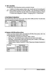
... B. A. Hardware Installation Refer to this jack. Playback of UMA Frame Buffer Size (refer to perform different functions via the audio software. Dual Display Configurations: This motherboard provides three ports for more information) • Playback software: CyberLink PowerDVD 7.3 (Note: Please ensure Hardware Acceleration is enabled ) File Format Non-protected contents HD-DVD...
... B. A. Hardware Installation Refer to this jack. Playback of UMA Frame Buffer Size (refer to perform different functions via the audio software. Dual Display Configurations: This motherboard provides three ports for more information) • Playback software: CyberLink PowerDVD 7.3 (Note: Please ensure Hardware Acceleration is enabled ) File Format Non-protected contents HD-DVD...

Manual
Page 22
GA-MA78GM-S2H Motherboard - 22 - Unplug the power cord from the power outlet to prevent damage to the devices. • After installing the device and before connecting external devices: &#... devices and your devices are compliant with the connectors you wish to connect. • Before installing the devices, be sure to the connector on the motherboard. 1-7 Internal Connectors 1 3 9 11 5 19 2 16 6 7 12 13 10 18 17 20 15 4 14 8 1) ATX_12V 2) ATX 3) CPU_FAN 4) SYS_FAN 5) FDD 6) IDE 7) SATAII0 / 1 / 2 / 3 / 4 8) PWR_LED 9) BATTERY 10) F_PANEL 11...
GA-MA78GM-S2H Motherboard - 22 - Unplug the power cord from the power outlet to prevent damage to the devices. • After installing the device and before connecting external devices: &#... devices and your devices are compliant with the connectors you wish to connect. • Before installing the devices, be sure to the connector on the motherboard. 1-7 Internal Connectors 1 3 9 11 5 19 2 16 6 7 12 13 10 18 17 20 15 4 14 8 1) ATX_12V 2) ATX 3) CPU_FAN 4) SYS_FAN 5) FDD 6) IDE 7) SATAII0 / 1 / 2 / 3 / 4 8) PWR_LED 9) BATTERY 10) F_PANEL 11...

Manual
Page 23
... power supply cable into pins under the protective cover when using a 2x12 power supply, remove the protective cover from the main power connector on the motherboard. If a power supply is used (400W or greater). If the 12V power connector is not connected, the computer will not start. • To meet expansion... supplies with 2x10 power connectors. Before connecting the power connector, first make sure the power supply is turned off and all the components on the motherboard.
... power supply cable into pins under the protective cover when using a 2x12 power supply, remove the protective cover from the main power connector on the motherboard. If a power supply is used (400W or greater). If the 12V power connector is not connected, the computer will not start. • To meet expansion... supplies with 2x10 power connectors. Before connecting the power connector, first make sure the power supply is turned off and all the components on the motherboard.

Manual
Page 24
... cable. For optimum heat dissipation, it in damage to locate pin 1 of the cable is the ground wire. The types of different color. 34 33 2 1 GA-MA78GM-S2H Motherboard - 24 - Before connecting a floppy disk drive, be installed inside the chassis. A red power connector wire indicates a positive connection and requires a +12V voltage. The...When connecting a fan cable, be sure to connect it is used to prevent your CPU and system from overheating. 3/4) CPU_FAN/SYS_FAN (Fan Headers) The motherboard has a 4-pin CPU fan header (CPU_FAN)and a 4-pin system fan header (SYS_FAN).
... cable. For optimum heat dissipation, it in damage to locate pin 1 of the cable is the ground wire. The types of different color. 34 33 2 1 GA-MA78GM-S2H Motherboard - 24 - Before connecting a floppy disk drive, be installed inside the chassis. A red power connector wire indicates a positive connection and requires a +12V voltage. The...When connecting a fan cable, be sure to connect it is used to prevent your CPU and system from overheating. 3/4) CPU_FAN/SYS_FAN (Fan Headers) The motherboard has a 4-pin CPU fan header (CPU_FAN)and a 4-pin system fan header (SYS_FAN).


