Manual
Page 4
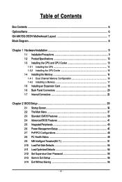
......6 GA-MA78G-DS3H Motherboard Layout 7 Block Diagram...8 Chapter 1 Hardware Installation 9 1-1 Installation Precautions 9 1-2 Product Specifications 10 1-3 Installing the CPU and CPU Cooler 13 1-3-1 Installing the CPU 13 1-3-2 Installing the CPU Cooler 15 1-4 Installing the Memory 16 1-4-1 Dual Channel Memory Configuration 16 1-4-2 Installing a Memory 17 1-5 Installing an Expansion Card 18 1-6 Back Panel Connectors 20 1-7 Internal Connectors 23 Chapter 2 BIOS Setup 35 2-1 Startup Screen 36 2-2 The Main Menu 37 2-3 Standard CMOS Features 39 2-4 Advanced BIOS Features...
......6 GA-MA78G-DS3H Motherboard Layout 7 Block Diagram...8 Chapter 1 Hardware Installation 9 1-1 Installation Precautions 9 1-2 Product Specifications 10 1-3 Installing the CPU and CPU Cooler 13 1-3-1 Installing the CPU 13 1-3-2 Installing the CPU Cooler 15 1-4 Installing the Memory 16 1-4-1 Dual Channel Memory Configuration 16 1-4-2 Installing a Memory 17 1-5 Installing an Expansion Card 18 1-6 Back Panel Connectors 20 1-7 Internal Connectors 23 Chapter 2 BIOS Setup 35 2-1 Startup Screen 36 2-2 The Main Menu 37 2-3 Standard CMOS Features 39 2-4 Advanced BIOS Features...
Manual
Page 10
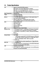
... 8 via the USB brackets connected to the internal USB headers) GA-MA78G-DS3H Motherboard - 10 - Support for CD In Realtek 8111C chip (10/100/1000 Mbit) 1 x PCI Express x16 slot(Note 3), conforming to PCI Express 2.0 standard. 1 x PCI Express x4 slot, conforming to PCI Express 2.0 standard. 3 x PCI Express x1 slots (PCIEX1_2, PCIEX1_3 share with the PCIEX4_1 slot) (Note 4) 2 x PCI slots South Bridge: - 1 x IDE connector supporting ATA-133/100/66/33 and up to 2 IDE devices - 6 x SATA 3Gb/s connectors supporting up to 1 floppy disk drive T.I. 1-2 Product Specifications CPU Š Hyper...
... 8 via the USB brackets connected to the internal USB headers) GA-MA78G-DS3H Motherboard - 10 - Support for CD In Realtek 8111C chip (10/100/1000 Mbit) 1 x PCI Express x16 slot(Note 3), conforming to PCI Express 2.0 standard. 1 x PCI Express x4 slot, conforming to PCI Express 2.0 standard. 3 x PCI Express x1 slots (PCIEX1_2, PCIEX1_3 share with the PCIEX4_1 slot) (Note 4) 2 x PCI slots South Bridge: - 1 x IDE connector supporting ATA-133/100/66/33 and up to 2 IDE devices - 6 x SATA 3Gb/s connectors supporting up to 1 floppy disk drive T.I. 1-2 Product Specifications CPU Š Hyper...
Manual
Page 12
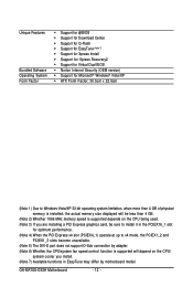
... PCIEX16_1 slot for optimum performance. (Note 4) When the PCI Express x4 slot (PCIEX4_1) operate at up to x4 mode, the PCIEX1_2 and PCIEX1_3 slots become unavailable. (Note 5) The DVI-D port does not support D-Sub connection by adapter. (Note 6) Whether the CPU/system fan speed control function is supported will depend on the CPU/ system cooler you install. (Note 7) Available functions in EasyTune may differ by motherboard model. GA-MA78G-DS3H Motherboard - 12...
... PCIEX16_1 slot for optimum performance. (Note 4) When the PCI Express x4 slot (PCIEX4_1) operate at up to x4 mode, the PCIEX1_2 and PCIEX1_3 slots become unavailable. (Note 5) The DVI-D port does not support D-Sub connection by adapter. (Note 6) Whether the CPU/system fan speed control function is supported will depend on the CPU/ system cooler you install. (Note 7) Available functions in EasyTune may differ by motherboard model. GA-MA78G-DS3H Motherboard - 12...
Manual
Page 16
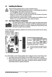
... unable to CPU limitation, read the following guidelines before installing the memory in the same colored DDR2 sockets for optimum performance. Enabling Dual Channel memory mode will automatically detect the specifications and capacity of the same capacity, brand, speed, and chips be used and installed in Dual Channel mode. 1. When enabling Dual Channel mode with two or four memory modules, it is installed, the BIOS will double the original memory bandwidth. GA-MA78G-DS3H Motherboard - 16 - Dual Channel mode cannot be installed in...
... unable to CPU limitation, read the following guidelines before installing the memory in the same colored DDR2 sockets for optimum performance. Enabling Dual Channel memory mode will automatically detect the specifications and capacity of the same capacity, brand, speed, and chips be used and installed in Dual Channel mode. 1. When enabling Dual Channel mode with two or four memory modules, it is installed, the BIOS will double the original memory bandwidth. GA-MA78G-DS3H Motherboard - 16 - Dual Channel mode cannot be installed in...
Manual
Page 18
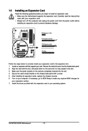
... the motherboard supports the expansion card. After installing all expansion cards, replace the chassis cover(s). 6. Locate an expansion slot that came with the expansion card in the expansion slot. 1. Install the driver provided with your operating system. Carefully read the manual that supports your expansion card in your expansion card. • Always turn off the computer and unplug the power cord from the chassis back panel. 2. Align the card with a screw. 5. GA-MA78G-DS3H Motherboard - 18...
... the motherboard supports the expansion card. After installing all expansion cards, replace the chassis cover(s). 6. Locate an expansion slot that came with the expansion card in the expansion slot. 1. Install the driver provided with your operating system. Carefully read the manual that supports your expansion card in your expansion card. • Always turn off the computer and unplug the power cord from the chassis back panel. 2. Align the card with a screw. 5. GA-MA78G-DS3H Motherboard - 18...
Manual
Page 20
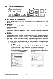
...the monitor being used. • After installing the HDMI device, make sure the default device for sound playback to this port. Connect a monitor that supports DVI-D connection to Realtek HDA HDMI Out. The HDMI Technology can support a maximum resolution of an external decoder for decoding.) In Windows XP, select Start>Control Panel>Sounds and Audio Devices>Audio, set the Default device for sound playback is HDCP compliant. DVI-D Port The DVI-D port supports DVI-D specifictation. GA-MA78G-DS3H Motherboard - 20 - Connect the HDMI audio/ video device to connect a PS/2 keyboard...
...the monitor being used. • After installing the HDMI device, make sure the default device for sound playback to this port. Connect a monitor that supports DVI-D connection to Realtek HDA HDMI Out. The HDMI Technology can support a maximum resolution of an external decoder for decoding.) In Windows XP, select Start>Control Panel>Sounds and Audio Devices>Audio, set the Default device for sound playback is HDCP compliant. DVI-D Port The DVI-D port supports DVI-D specifictation. GA-MA78G-DS3H Motherboard - 20 - Connect the HDMI audio/ video device to connect a PS/2 keyboard...
Manual
Page 25
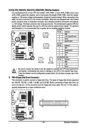
...supported are not configuration jumper blocks. Before connecting a floppy disk drive, be installed inside the chassis. CPU_FAN: Pin No. When connecting a fan cable, be sure to connect it is the ground wire. 3/4/5/6) CPU_FAN/SYS_FAN1/SYS_FAN2/PWR_FAN (Fan Headers) The motherboard has a 4-pin CPU fan header (CPU_FAN), a 3-pin (SYS_FAN2) and a 4-pin (SYS_FAN1) system fan headers, and a 3-pin power fan header (PWR_FAN). Each fan header supplies a +12V power voltage and possesses a foolproof insertion design. The motherboard supports CPU fan speed control, which requires the use...
...supported are not configuration jumper blocks. Before connecting a floppy disk drive, be installed inside the chassis. CPU_FAN: Pin No. When connecting a fan cable, be sure to connect it is the ground wire. 3/4/5/6) CPU_FAN/SYS_FAN1/SYS_FAN2/PWR_FAN (Fan Headers) The motherboard has a 4-pin CPU fan header (CPU_FAN), a 3-pin (SYS_FAN2) and a 4-pin (SYS_FAN1) system fan headers, and a 3-pin power fan header (PWR_FAN). Each fan header supplies a +12V power voltage and possesses a foolproof insertion design. The motherboard supports CPU fan speed control, which requires the use...
Manual
Page 33
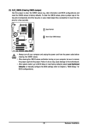
... the motherboard. • After system restart, go to BIOS Setup to load factory defaults (select Load Optimized Defaults) or manually configure the BIOS settings (refer to touch the two pins for BIOS configurations). - 33 - To clear the CMOS values, place a jumper cap on your computer, be sure to remove the jumper cap from the power outlet before clearing the CMOS values. • After clearing the CMOS values and before turning on the two pins to temporarily short...
... the motherboard. • After system restart, go to BIOS Setup to load factory defaults (select Load Optimized Defaults) or manually configure the BIOS settings (refer to touch the two pins for BIOS configurations). - 33 - To clear the CMOS values, place a jumper cap on your computer, be sure to remove the jumper cap from the power outlet before clearing the CMOS values. • After clearing the CMOS values and before turning on the two pins to temporarily short...
Manual
Page 41
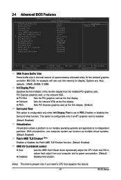
...PEG Sets PCI Express graphics card as multiple virtual systems. (Default: Disabled) Patch AMD TLB Erratum (Note) Enables or disables the Patch AMD TLB Erratum function. (Default: Enabled) AMD K8 Cool&Quiet control Auto Disabled Lets the AMD Cool'n'Quiet driver dynamically adjust the CPU clock and VIA to reduce heat output from the installed PCI graphics card, PCI Express graphics card, or the onboard VGA. Capability Away Mode Full Screen LOGO Show [Auto] [PEG] [Disabled] [Disabled] [Enabled] [Auto] [Press Enter] [Floppy] [Hard Disk] [CDROM] [Setup] [Disabled] [Disabled] [Enabled...
...PEG Sets PCI Express graphics card as multiple virtual systems. (Default: Disabled) Patch AMD TLB Erratum (Note) Enables or disables the Patch AMD TLB Erratum function. (Default: Enabled) AMD K8 Cool&Quiet control Auto Disabled Lets the AMD Cool'n'Quiet driver dynamically adjust the CPU clock and VIA to reduce heat output from the installed PCI graphics card, PCI Express graphics card, or the onboard VGA. Capability Away Mode Full Screen LOGO Show [Auto] [PEG] [Disabled] [Disabled] [Enabled] [Auto] [Press Enter] [Floppy] [Hard Disk] [CDROM] [Setup] [Disabled] [Disabled] [Enabled...
Manual
Page 42
... entering the BIOS Setup program. (Default) A password is required every time the system boots, or only when you to determine whether to issue warnings when a third party hardware monitor utility is installed. (Default: Disabled) Away Mode Enables or disables Away Mode in the BIOS Main Menu. This feature allows your hard drive. Use the up or down arrow key to select a device and press to accept. Options are: Floppy, LS120, Hard Disk, CDROM, ZIP, USB-FDD, USB-ZIP, USB-CDROM, USB-HDD, Legacy LAN, Disabled. HDD...
... entering the BIOS Setup program. (Default) A password is required every time the system boots, or only when you to determine whether to issue warnings when a third party hardware monitor utility is installed. (Default: Disabled) Away Mode Enables or disables Away Mode in the BIOS Main Menu. This feature allows your hard drive. Use the up or down arrow key to select a device and press to accept. Options are: Floppy, LS120, Hard Disk, CDROM, ZIP, USB-FDD, USB-ZIP, USB-CDROM, USB-HDD, Legacy LAN, Disabled. HDD...
Manual
Page 43
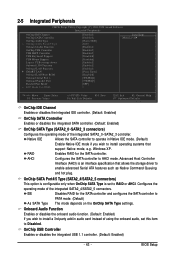
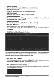
... RAID for the SATA controller and configures the SATA controller to AHCI mode. Configures the operating mode of the integrated SATA2_0~SATA2_3 controller. BIOS Setup 2-5 Integrated Peripherals CMOS Setup Utility-Copyright (C) 1984-2008 Award Software Integrated Peripherals OnChip IDE Channel OnChip SATA Controller OnChip SATA Type x OnChip SATA Port4/5 Type Onboard Audio Function OnChip USB Controller USB EHCI Controller USB Keyboard Support USB Mouse Support Legacy USB storage detect Onboard 1394 Function Onboard LAN Function ` SMART LAN Onboard LAN Boot ROM Onboard Serial Port 1 Onboard...
... RAID for the SATA controller and configures the SATA controller to AHCI mode. Configures the operating mode of the integrated SATA2_0~SATA2_3 controller. BIOS Setup 2-5 Integrated Peripherals CMOS Setup Utility-Copyright (C) 1984-2008 Award Software Integrated Peripherals OnChip IDE Channel OnChip SATA Controller OnChip SATA Type x OnChip SATA Port4/5 Type Onboard Audio Function OnChip USB Controller USB EHCI Controller USB Keyboard Support USB Mouse Support Legacy USB storage detect Onboard 1394 Function Onboard LAN Function ` SMART LAN Onboard LAN Boot ROM Onboard Serial Port 1 Onboard...
Manual
Page 44
... USB 2.0 controller. (Default: Enabled) USB Keyboard Support Allows USB keyboard to be used in MS-DOS. (Default: Disabled) USB Mouse Support Allows USB mouse to be used in MS-DOS. (Default: Disabled) Legacy USB storage detect Determines whether to detect USB storage devices, including USB flash drives and USB hard drives during the POST. (Default: Enabled) Onboard 1394 Function Enables or disables the onboard IEEE 1394 function. (Default: Enabled) Onboard LAN Function Enables or disables the onboard LAN function. (Default: Enabled) If you wish to install a 3rd party add-in network card...
... USB 2.0 controller. (Default: Enabled) USB Keyboard Support Allows USB keyboard to be used in MS-DOS. (Default: Disabled) USB Mouse Support Allows USB mouse to be used in MS-DOS. (Default: Disabled) Legacy USB storage detect Determines whether to detect USB storage devices, including USB flash drives and USB hard drives during the POST. (Default: Enabled) Onboard 1394 Function Enables or disables the onboard IEEE 1394 function. (Default: Enabled) Onboard LAN Function Enables or disables the onboard LAN function. (Default: Enabled) If you wish to install a 3rd party add-in network card...

Manual
Page 45
... wires, the Status field will show Short and thenlength shown will show Open, and the length shown is the approximate length of 10/100/1000 Mbps in Windows mode or when the LAN Boot ROM is set to activate the boot ROM integrated with the onboard LAN chip. (Default: Disabled) Onboard Serial Port 1 Enables or disables the first serial port and specifies its base I /O address and corresponding interrupt. Options are : 3 (default), 1. - 45 - Link Detected Cable...
... wires, the Status field will show Short and thenlength shown will show Open, and the length shown is the approximate length of 10/100/1000 Mbps in Windows mode or when the LAN Boot ROM is set to activate the boot ROM integrated with the onboard LAN chip. (Default: Disabled) Onboard Serial Port 1 Enables or disables the first serial port and specifies its base I /O address and corresponding interrupt. Options are : 3 (default), 1. - 45 - Link Detected Cable...
Manual
Page 46
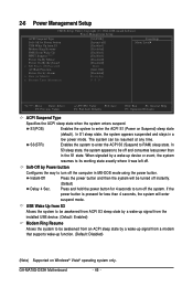
... Defaults ACPI Suspend Type Specifies the ACPI sleep state when the system enters suspend. GA-MA78G-DS3H Motherboard - 46 - 2-6 Power Management Setup CMOS Setup Utility-Copyright (C) 1984-2008 Award Software Power Management Setup ACPI Suspend Type Soft-Off by Power button USB Wake Up from S3 Modem Ring Resume PME Event Wake Up HPET Support (Note) Power On By Mouse Power On By Keyboard x KB Power ON Password AC Back Function Power-On by a wake-up function. (Default: Disabled) (Note) Supported on Suspend) sleep state (default). In S3 sleep state...
... Defaults ACPI Suspend Type Specifies the ACPI sleep state when the system enters suspend. GA-MA78G-DS3H Motherboard - 46 - 2-6 Power Management Setup CMOS Setup Utility-Copyright (C) 1984-2008 Award Software Power Management Setup ACPI Suspend Type Soft-Off by Power button USB Wake Up from S3 Modem Ring Resume PME Event Wake Up HPET Support (Note) Power On By Mouse Power On By Keyboard x KB Power ON Password AC Back Function Power-On by a wake-up function. (Default: Disabled) (Note) Supported on Suspend) sleep state (default). In S3 sleep state...
Manual
Page 50
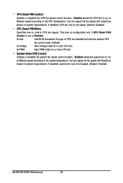
... temperature. PWM Sets PWM mode for a 3-pin CPU fan. If disabled, system fan runs at full speed. (Default: Enabled) CPU Smart FAN Mode Specifies how to Enabled. You can adjust the fan speed with EasyTune based on system requirements. You can adjust the fan speed with EasyTune based on system requirements. This item is configurable only if CPU Smart FAN Control is set to control CPU fan speed. Auto Lets BIOS autodetect the type of CPU fan installed and sets the optimal CPU fan control mode. (Default) Voltage Sets Voltage mode for a 4-pin CPU fan. CPU Smart FAN...
... temperature. PWM Sets PWM mode for a 3-pin CPU fan. If disabled, system fan runs at full speed. (Default: Enabled) CPU Smart FAN Mode Specifies how to Enabled. You can adjust the fan speed with EasyTune based on system requirements. You can adjust the fan speed with EasyTune based on system requirements. This item is configurable only if CPU Smart FAN Control is set to control CPU fan speed. Auto Lets BIOS autodetect the type of CPU fan installed and sets the optimal CPU fan control mode. (Default) Voltage Sets Voltage mode for a 4-pin CPU fan. CPU Smart FAN...
Manual
Page 51
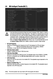
... used . 2-9 MB Intelligent Tweaker(M.I.T.) CMOS Setup Utility-Copyright (C) 1984-2008 Award Software MB Intelligent Tweaker(M.I.T.) HT Link Frequency VGA Core Clock control x VGA Core Clock (Mhz) CPU Clock Ratio Memory Controller Freq. (Note) CPU Host Clock Control x CPU Frequency (MHz) PCIE Clock (MHz) Set Memory Clock x Memory Clock DCTs Mode (Note) ******** System Voltage Optimized System Voltage Control x DDR2 Voltage Control x NorthBridge Volt Control x SouthBridge Volt Control x CPU NB VID Control (Note) x CPU Voltage Control Normal CPU Vcore ******** [Auto] [Disabled] 500 [Auto...
... used . 2-9 MB Intelligent Tweaker(M.I.T.) CMOS Setup Utility-Copyright (C) 1984-2008 Award Software MB Intelligent Tweaker(M.I.T.) HT Link Frequency VGA Core Clock control x VGA Core Clock (Mhz) CPU Clock Ratio Memory Controller Freq. (Note) CPU Host Clock Control x CPU Frequency (MHz) PCIE Clock (MHz) Set Memory Clock x Memory Clock DCTs Mode (Note) ******** System Voltage Optimized System Voltage Control x DDR2 Voltage Control x NorthBridge Volt Control x SouthBridge Volt Control x CPU NB VID Control (Note) x CPU Voltage Control Normal CPU Vcore ******** [Auto] [Disabled] 500 [Auto...
Manual
Page 56
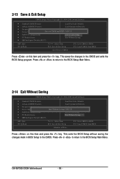
... item and press the key. This exits the BIOS Setup without saving the changes made in BIOS Setup to the BIOS Setup Main Menu. Press or to return to the CMOS. GA-MA78G-DS3H Motherboard - 56 - 2-13 Save & Exit Setup CMOS Setup Utility-Copyright (C) 1984-2008 Award Software ` Standard CMOS Features Load Fail-Safe Defaults ` Advanced BIOS Features Load Optimized Defaults ` Integrated Peripherals Set Supervisor Password ` Power Management Setup Save to CMOS and EXIT (SYe/tNU)?seYr Password ` PnP/PCI Configurations Save & Exit Setup ` PC Health Status...
... item and press the key. This exits the BIOS Setup without saving the changes made in BIOS Setup to the BIOS Setup Main Menu. Press or to return to the CMOS. GA-MA78G-DS3H Motherboard - 56 - 2-13 Save & Exit Setup CMOS Setup Utility-Copyright (C) 1984-2008 Award Software ` Standard CMOS Features Load Fail-Safe Defaults ` Advanced BIOS Features Load Optimized Defaults ` Integrated Peripherals Set Supervisor Password ` Power Management Setup Save to CMOS and EXIT (SYe/tNU)?seYr Password ` PnP/PCI Configurations Save & Exit Setup ` PC Health Status...
Manual
Page 73
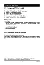
... it is set to AHCI or RAID mode. - 73 - Installing SATA hard drive(s) in RAID BIOS. (Note 1) D. Install the SATA RAID/AHCI driver and operating system. (Note 2) Before you do not want to create RAID array on the motherboard. B. Appendix Configure SATA controller mode in your computer. C . Make a floppy disk containing the SATA RAID/AHCI driver. (Note 2) E. Then connect the power connector from your computer Attach one hard drive. • An empty formatted floppy disk. • Windows Vista/XP setup disk. • Motherboard driver disk. 5-1-1 Configuring the Onboard SATA...
... it is set to AHCI or RAID mode. - 73 - Installing SATA hard drive(s) in RAID BIOS. (Note 1) D. Install the SATA RAID/AHCI driver and operating system. (Note 2) Before you do not want to create RAID array on the motherboard. B. Appendix Configure SATA controller mode in your computer. C . Make a floppy disk containing the SATA RAID/AHCI driver. (Note 2) E. Then connect the power connector from your computer Attach one hard drive. • An empty formatted floppy disk. • Windows Vista/XP setup disk. • Motherboard driver disk. 5-1-1 Configuring the Onboard SATA...
Manual
Page 80
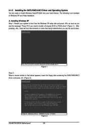
... chosen to install Windows Vista/XP/2000 onto your system to boot from the Windows XP setup disk and press as soon as you see the next screen. Figure 1 Step 2: When a screen similar to install a third party SCSI or RAID driver. Currently, Setup will be a few moments of Windows XP and Vista installation. Installing Windows XP Step 1: Restart your hard drive(s). S=Specify Additional Device ENTER=Continue F3=Exit Figure 2 GA-MA78G-DS3H Motherboard - 80...
... chosen to install Windows Vista/XP/2000 onto your system to boot from the Windows XP setup disk and press as soon as you see the next screen. Figure 1 Step 2: When a screen similar to install a third party SCSI or RAID driver. Currently, Setup will be a few moments of Windows XP and Vista installation. Installing Windows XP Step 1: Restart your hard drive(s). S=Specify Additional Device ENTER=Continue F3=Exit Figure 2 GA-MA78G-DS3H Motherboard - 80...
Manual
Page 92
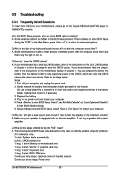
... steps below: Steps: 1. If not, try a speaker with an internal amplifier. Q:What do the beeps emitted during the POST. A: The following Award BIOS beep code descriptions may help you identify possible computer problems. (For reference only.) 1 short: System boots successfully 2 short: CMOS setting error 1 long, 1 short: Memory or motherboard error 1 long, 2 short: Monitor or graphics card error 1 long, 3 short: Keyboard error 1 long, 9 short: BIOS ROM error Continuous long beeps: Graphics card not inserted properly Continuous short beeps: Power error GA-MA78G-DS3H Motherboard - 92 -
... steps below: Steps: 1. If not, try a speaker with an internal amplifier. Q:What do the beeps emitted during the POST. A: The following Award BIOS beep code descriptions may help you identify possible computer problems. (For reference only.) 1 short: System boots successfully 2 short: CMOS setting error 1 long, 1 short: Memory or motherboard error 1 long, 2 short: Monitor or graphics card error 1 long, 3 short: Keyboard error 1 long, 9 short: BIOS ROM error Continuous long beeps: Graphics card not inserted properly Continuous short beeps: Power error GA-MA78G-DS3H Motherboard - 92 -


