Manual
Page 3
Changes to their respective owners. For product-related information, check on our website at: http://www.gigabyte.com.tw Identifying Your Motherboard Revision The revision number on your motherboard revision before updating motherboard BIOS, drivers, or when looking for technical information. For example, "REV: 1.0" means the revision of the motherboard is the property...
Changes to their respective owners. For product-related information, check on our website at: http://www.gigabyte.com.tw Identifying Your Motherboard Revision The revision number on your motherboard revision before updating motherboard BIOS, drivers, or when looking for technical information. For example, "REV: 1.0" means the revision of the motherboard is the property...
Manual
Page 4
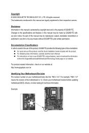
Table of Contents Box Contents...6 Optional Items...6 GA-MA785GPMT-UD2H/GA-MA785GMT-UD2H(US2H 7 Motherboard Layout...7 Block Diagram...8 Chapter 1 Hardware Installation 9 1-1 Installation Precautions 9 1-2 Product Specifications 10 1-3 Installing the CPU and...8482; Configuration 19 1-7 Back Panel Connectors 20 1-8 Internal Connectors 23 Chapter 2 BIOS Setup 35 2-1 Startup Screen 36 2-2 The Main Menu 37 2-3 MB Intelligent Tweaker(M.I.T 39 2-4 Standard CMOS Features 45 2-5 Advanced BIOS Features 47 2-6 Integrated Peripherals 50 2-7 Power Management Setup 53 2-8 PnP/PCI ...
Table of Contents Box Contents...6 Optional Items...6 GA-MA785GPMT-UD2H/GA-MA785GMT-UD2H(US2H 7 Motherboard Layout...7 Block Diagram...8 Chapter 1 Hardware Installation 9 1-1 Installation Precautions 9 1-2 Product Specifications 10 1-3 Installing the CPU and...8482; Configuration 19 1-7 Back Panel Connectors 20 1-8 Internal Connectors 23 Chapter 2 BIOS Setup 35 2-1 Startup Screen 36 2-2 The Main Menu 37 2-3 MB Intelligent Tweaker(M.I.T 39 2-4 Standard CMOS Features 45 2-5 Advanced BIOS Features 47 2-6 Integrated Peripherals 50 2-7 Power Management Setup 53 2-8 PnP/PCI ...
Manual
Page 5
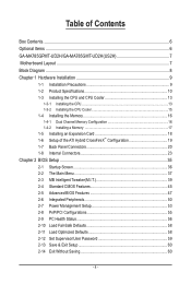
... Only for GA-MA785GPMT-UD2H. Chapter 3 Drivers Installation 61 3-1 Installing Chipset Drivers 61 3-2 Application Software 62 3-3 Technical Manuals 62 3-4 Contact...63 3-5 System...63 3-6 Download Center 64 Chapter 4 Unique Features 65 4-1 Xpress Recovery2 65 4-2 BIOS Update Utilities 68 4-2-1 Updating the BIOS with the Q-Flash Utility 68 4-2-2 Updating the BIOS with the @BIOS Utility 71 ... Using the Sound Recorder 95 5-3 Troubleshooting 96 5-3-1 Frequently Asked Questions 96 5-3-2 Troubleshooting Procedure 97 5-4 Regulatory Statements 99 j Only for GA-MA785GMT-UD2H. - 5 -
... Only for GA-MA785GPMT-UD2H. Chapter 3 Drivers Installation 61 3-1 Installing Chipset Drivers 61 3-2 Application Software 62 3-3 Technical Manuals 62 3-4 Contact...63 3-5 System...63 3-6 Download Center 64 Chapter 4 Unique Features 65 4-1 Xpress Recovery2 65 4-2 BIOS Update Utilities 68 4-2-1 Updating the BIOS with the Q-Flash Utility 68 4-2-2 Updating the BIOS with the @BIOS Utility 71 ... Using the Sound Recorder 95 5-3 Troubleshooting 96 5-3-1 Frequently Asked Questions 96 5-3-2 Troubleshooting Procedure 97 5-4 Regulatory Statements 99 j Only for GA-MA785GMT-UD2H. - 5 -

Manual
Page 8
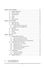
... Express x16 Dual Channel Memory Hyper Transport 3.0 PCI Express x16 PCI Express Bus x1 PCIe CLK (100 MHz) 1 PCI Express x1 RTL8111C RJ45 LAN Dual BIOS PCI Bus TSB43AB23 2 IEEE 1394a AMD 785G GFX CLK (100 MHz) D-Sub DVI-D or HDMI (Note) DDR3 SidePort Memoryj 12 USB Ports AMD SB710 ATA... Speaker Out Center/Subwoofer Speaker Out Side Speaker Out MIC Line Out Line In S/PDIF In S/ PDIF Out 2 PCI PCI CLK (33 MHz) j Only for GA-MA785GPMT-UD2H. (Note) Simultaneous output for DVI-D and HDMI is not supported. - 8 -
... Express x16 Dual Channel Memory Hyper Transport 3.0 PCI Express x16 PCI Express Bus x1 PCIe CLK (100 MHz) 1 PCI Express x1 RTL8111C RJ45 LAN Dual BIOS PCI Bus TSB43AB23 2 IEEE 1394a AMD 785G GFX CLK (100 MHz) D-Sub DVI-D or HDMI (Note) DDR3 SidePort Memoryj 12 USB Ports AMD SB710 ATA... Speaker Out Center/Subwoofer Speaker Out Side Speaker Out MIC Line Out Line In S/PDIF In S/ PDIF Out 2 PCI PCI CLK (33 MHz) j Only for GA-MA785GPMT-UD2H. (Note) Simultaneous output for DVI-D and HDMI is not supported. - 8 -
Manual
Page 12
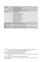
... Features w w w w w w w w w w Bundled Software w 2 x 8 Mbit flash Use of licensed AWARD BIOS Support for DualBIOS™ PnP 1.0a, DMI 2.0, SM BIOS 2.4, ACPI 1.0b Support for @BIOS Support for Q-Flash Support for Xpress BIOS Rescue Support for Download Center Support for Xpress Install Support for Xpress Recovery2 Support for EasyTune (Note 5) Support for Easy Energy Saver Support...
... Features w w w w w w w w w w Bundled Software w 2 x 8 Mbit flash Use of licensed AWARD BIOS Support for DualBIOS™ PnP 1.0a, DMI 2.0, SM BIOS 2.4, ACPI 1.0b Support for @BIOS Support for Q-Flash Support for Xpress BIOS Rescue Support for Download Center Support for Xpress Install Support for Xpress Recovery2 Support for EasyTune (Note 5) Support for Easy Energy Saver Support...
Manual
Page 16
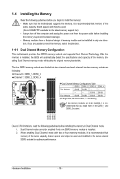
... DS/SS DS/SS - - - - - - - - When enabling Dual Channel mode with two or four memory modules, it is installed. 2. A memory module can be used . (Go to GIGABYTE's website for optimum performance. If you install them in only one DDR3 memory module is recommended that memory of the same capacity, brand, speed, and... - After the memory is recommended that you are to install the memory: • Make sure that the motherboard supports the memory. It is installed, the BIOS will double the original memory bandwidth.
... DS/SS DS/SS - - - - - - - - When enabling Dual Channel mode with two or four memory modules, it is installed. 2. A memory module can be used . (Go to GIGABYTE's website for optimum performance. If you install them in only one DDR3 memory module is recommended that memory of the same capacity, brand, speed, and... - After the memory is recommended that you are to install the memory: • Make sure that the motherboard supports the memory. It is installed, the BIOS will double the original memory bandwidth.
Manual
Page 18
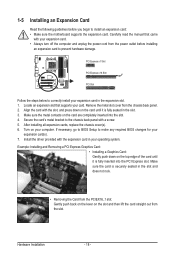
... into the slot. 4. Remove the metal slot cover from the slot. Secure the card's metal bracket to make any required BIOS changes for your operating system. If necessary, go to BIOS Setup to the chassis back panel with the expansion card in the slot and does not rock. • Removing the Card...
... into the slot. 4. Remove the metal slot cover from the slot. Secure the card's metal bracket to make any required BIOS changes for your operating system. If necessary, go to BIOS Setup to the chassis back panel with the expansion card in the slot and does not rock. • Removing the Card...
Manual
Page 19
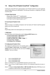
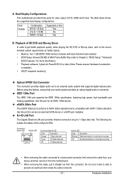
... into the onboard graphics port on configuring an ATI Hybrid CrossFireX system. Set Init Display First to disable the CrossFire function in BIOS Setup, be sure to OnChipVGA. stalled. (Note 3) To change the Internal Graphics Mode or UMA Frame Buffer Size setting in... CrossFireX™ Configuration Combining the onboard GPU with a discrete graphics card, ATI Hybrid CrossFireX can provide significantly advanced display performance for GA-MA785GPMT-UD2H. This section give instructions on the back panel. Windows Vista or Windows XP (Note 1) operating system - An ATI Hybrid CrossFireX...
... into the onboard graphics port on configuring an ATI Hybrid CrossFireX system. Set Init Display First to disable the CrossFire function in BIOS Setup, be sure to OnChipVGA. stalled. (Note 3) To change the Internal Graphics Mode or UMA Frame Buffer Size setting in... CrossFireX™ Configuration Combining the onboard GPU with a discrete graphics card, ATI Hybrid CrossFireX can provide significantly advanced display performance for GA-MA785GPMT-UD2H. This section give instructions on the back panel. Windows Vista or Windows XP (Note 1) operating system - An ATI Hybrid CrossFireX...
Manual
Page 21
... Ethernet LAN port provides Internet connection at up to SATA 3Gb/s standard and is compatible with dual channel mode enabled • BIOS Setup: At least 256 MB of the LAN port LEDs. Before using this port for video output: DVI-D, HDMI and D-...electrical short inside the cable connector. - 21 - The following describes the states of UMA Frame Buffer Size (refer to Chapter 2, "BIOS Setup," "Advanced BIOS Features," for more information) • Playback software: CyberLink PowerDVD 8.0 or later (Note: Please ensure Hardware Acceleration is occurring •...
... Ethernet LAN port provides Internet connection at up to SATA 3Gb/s standard and is compatible with dual channel mode enabled • BIOS Setup: At least 256 MB of the LAN port LEDs. Before using this port for video output: DVI-D, HDMI and D-...electrical short inside the cable connector. - 21 - The following describes the states of UMA Frame Buffer Size (refer to Chapter 2, "BIOS Setup," "Advanced BIOS Features," for more information) • Playback software: CyberLink PowerDVD 8.0 or later (Note: Please ensure Hardware Acceleration is occurring •...

Manual
Page 28
... the problem. The LED S0 On is in S1 sleep state. One single short beep will be heard if no problem is detected, the BIOS may configure the way to turn off when the system is on the chassis front panel. If a problem is detected at system startup. A...LED, Yellow): System Status LED Connects to the speaker on the chassis front panel. When connecting your system using the power switch (refer to Chapter 2, "BIOS Setup," "Power Management Setup," for information about beep codes. • HD (Hard Drive Activity LED, Blue) Connects to the pin assignments below. Refer...
... the problem. The LED S0 On is in S1 sleep state. One single short beep will be heard if no problem is detected, the BIOS may configure the way to turn off when the system is on the chassis front panel. If a problem is detected at system startup. A...LED, Yellow): System Status LED Connects to the speaker on the chassis front panel. When connecting your system using the power switch (refer to Chapter 2, "BIOS Setup," "Power Management Setup," for information about beep codes. • HD (Hard Drive Activity LED, Blue) Connects to the pin assignments below. Refer...

Manual
Page 33
..., note the orientation of the positive side (+) and the negative side (-) of the battery holder, making them short for 5 seconds.) 3. date information and BIOS configurations) and reset the CMOS values to clear the CMOS values (e.g. Replace the battery when the battery voltage drops to a low level, or the CMOS... unplug the power cord before turning on the two pins to temporarily short the two pins or use a metal object like a screwdriver to Chapter 2, "BIOS Setup," for a few seconds. Replace the battery. 4. Danger of purchase or local dealer if you are not able to do so may be handled...
..., note the orientation of the positive side (+) and the negative side (-) of the battery holder, making them short for 5 seconds.) 3. date information and BIOS configurations) and reset the CMOS values to clear the CMOS values (e.g. Replace the battery when the battery voltage drops to a low level, or the CMOS... unplug the power cord before turning on the two pins to temporarily short the two pins or use a metal object like a screwdriver to Chapter 2, "BIOS Setup," for a few seconds. Replace the battery. 4. Danger of purchase or local dealer if you are not able to do so may be handled...

Manual
Page 35
... and reset the board to default values. (Refer to boot. BIOS includes a BIOS Setup program that searches and downloads the latest version of the BIOS Setup program. To upgrade the BIOS, use either the GIGABYTE Q-Flash or @BIOS utility. • Q-Flash allows the user to quickly and easily... upgrade or back up BIOS without entering the operating system. • @BIOS is turned on the motherboard. Inadequately...
... and reset the board to default values. (Refer to boot. BIOS includes a BIOS Setup program that searches and downloads the latest version of the BIOS Setup program. To upgrade the BIOS, use either the GIGABYTE Q-Flash or @BIOS utility. • Q-Flash allows the user to quickly and easily... upgrade or back up BIOS without entering the operating system. • @BIOS is turned on the motherboard. Inadequately...
Manual
Page 36
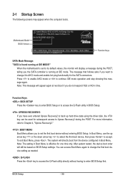
...: Q-FLASH Press the key to continue IDE mode operation and stop showing this message again. Function Keys: : BIOS SETUP Press the key to enter BIOS Setup or to enter BIOS Setup first. For more information, refer to Chapter 4, "Xpress Recovery2." : BOOT MENU Boot Menu allows you...accept. The system will display a message during the POST. You can be based on BIOS Setup settings. After system restart, the device boot order will appear again at IDE MODE!" GA-MA785GPMT-UD2H E3c . . . . : BIOS Setup : XpressRecovery2 : Boot Menu : Qflash 06/05/2009-RS785-SB710-7A66BG03C-00 ...
...: Q-FLASH Press the key to continue IDE mode operation and stop showing this message again. Function Keys: : BIOS SETUP Press the key to enter BIOS Setup or to enter BIOS Setup first. For more information, refer to Chapter 4, "Xpress Recovery2." : BOOT MENU Boot Menu allows you...accept. The system will display a message during the POST. You can be based on BIOS Setup settings. After system restart, the device boot order will appear again at IDE MODE!" GA-MA785GPMT-UD2H E3c . . . . : BIOS Setup : XpressRecovery2 : Boot Menu : Qflash 06/05/2009-RS785-SB710-7A66BG03C-00 ...
Manual
Page 37
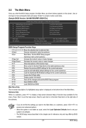
...of function keys available for reference only and may differ by BIOS version. - 37 - Use arrow keys to move among the items and press to accept or enter a sub-menu. (Sample BIOS Version: GA-MA785GPMT-UD2H E3c) CMOS Setup Utility-Copyright (C) 1984-2009 Award Software... MB Intelligent Tweaker(M.I.T.) Standard CMOS Features Advanced BIOS Features Integrated Peripherals Power Management Setup ...
...of function keys available for reference only and may differ by BIOS version. - 37 - Use arrow keys to move among the items and press to accept or enter a sub-menu. (Sample BIOS Version: GA-MA785GPMT-UD2H E3c) CMOS Setup Utility-Copyright (C) 1984-2009 Award Software... MB Intelligent Tweaker(M.I.T.) Standard CMOS Features Advanced BIOS Features Integrated Peripherals Power Management Setup ...

Manual
Page 38
...61550; MB Intelligent Tweaker(M.I.T.) Use this menu to configure the clock, frequency and voltages of your system becomes unstable and you have loaded the BIOS default settings, you can also carry out this function to see information about autodetected system/CPU temperature, system voltage and fan speed, etc. ... and date, hard drive types, floppy disk drive types, and the type of errors that stop the system boot, etc. Advanced BIOS Features Use this menu to configure the device boot order, advanced features available on the CPU, and the primary display adapter. Integrated...
...61550; MB Intelligent Tweaker(M.I.T.) Use this menu to configure the clock, frequency and voltages of your system becomes unstable and you have loaded the BIOS default settings, you can also carry out this function to see information about autodetected system/CPU temperature, system voltage and fan speed, etc. ... and date, hard drive types, floppy disk drive types, and the type of errors that stop the system boot, etc. Advanced BIOS Features Use this menu to configure the device boot order, advanced features available on the CPU, and the primary display adapter. Integrated...
Manual
Page 39
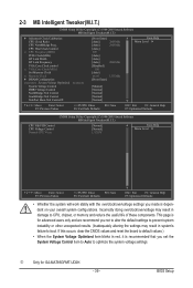
.... (Inadequately altering the settings may result in red, it is for GA-MA785GPMT-UD2H. - 39 - If this occurs, clear the CMOS values and reset the board to default values.) • When the System Voltage Optimized item blinks in damage to boot. BIOS Setup j Only for advanced users only and we recommend you set the...
.... (Inadequately altering the settings may result in red, it is for GA-MA785GPMT-UD2H. - 39 - If this occurs, clear the CMOS values and reset the board to default values.) • When the System Voltage Optimized item blinks in damage to boot. BIOS Setup j Only for advanced users only and we recommend you set the...

Manual
Page 40
... Clock Calibration for each CPU core. Per Core Individually configures Advanced Clock Calibration for all CPU cores. Options are : -12%~+12%. BIOS Setup - 40 - A message which says "BIOS Is Updating EC Firmware!!! Wait for the settings to defaults. Value (Core 0), Value (Core 1), Value (Core 2), Value (Core ... set to enable Advanced Clock Calibration when using an AMD Black Edition CPU. After the selection, select Save & Exit Setup in the BIOS Main Menu and then press . Don't Turn Off Or Reset System" will automatically restart for a few seconds and the system will appear...
... Clock Calibration for each CPU core. Per Core Individually configures Advanced Clock Calibration for all CPU cores. Options are : -12%~+12%. BIOS Setup - 40 - A message which says "BIOS Is Updating EC Firmware!!! Wait for the settings to defaults. Value (Core 0), Value (Core 1), Value (Core 2), Value (Core ... set to enable Advanced Clock Calibration when using an AMD Black Edition CPU. After the selection, select Save & Exit Setup in the BIOS Main Menu and then press . Don't Turn Off Or Reset System" will automatically restart for a few seconds and the system will appear...

Manual
Page 41
...to manually set the CPU host frequency. CPU NorthBridge Freq. Allows you to manually set the width for the installed CPU. Auto (default) allows the BIOS to x1~x10 (200 MHz~2.0 GHz). Manual allows the CPU Frequency (MHz) item below to be configurable. (Default: Auto) Memory Clock This option... to alter the North Bridge controller frequency for automated system reboot, or clear the CMOS values to reset the board to 500 MHz. Auto BIOS will automatically adjust the HT Link Frequency. (Default) x1~x10 Sets HT Link Frequency to automatically adjust the CPU host frequency. VGA Core ...
...to manually set the CPU host frequency. CPU NorthBridge Freq. Allows you to manually set the width for the installed CPU. Auto (default) allows the BIOS to x1~x10 (200 MHz~2.0 GHz). Manual allows the CPU Frequency (MHz) item below to be configurable. (Default: Auto) Memory Clock This option... to alter the North Bridge controller frequency for automated system reboot, or clear the CMOS values to reset the board to 500 MHz. Auto BIOS will automatically adjust the HT Link Frequency. (Default) x1~x10 Sets HT Link Frequency to automatically adjust the CPU host frequency. VGA Core ...
Manual
Page 42
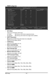
... Time x Row Cycle Time x RAS to RAS Delay Bank interleaving Channel interleave [Unganged] [Auto] SPD Auto 7T Auto 7T Auto 7T Auto 30T Auto -- Auto -- BIOS Setup - 42 - Auto 5T Auto 90ns Auto -- DRAM Configuration CMOS Setup Utility-Copyright (C) 1984-2009 Award Software DRAM Configuration DCTs Mode DDR3 Timing Items x CAS...
... Time x Row Cycle Time x RAS to RAS Delay Bank interleaving Channel interleave [Unganged] [Auto] SPD Auto 7T Auto 7T Auto 7T Auto 30T Auto -- Auto -- BIOS Setup - 42 - Auto 5T Auto 90ns Auto -- DRAM Configuration CMOS Setup Utility-Copyright (C) 1984-2009 Award Software DRAM Configuration DCTs Mode DDR3 Timing Items x CAS...
Manual
Page 43
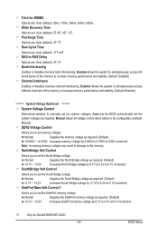
...) -0.1V ~ +0.2V Increases South Bridge voltage by 0.1V to 0.2V at 0.1V increment. BIOS Setup Auto lets the BIOS automatically set memory voltage. Normal Supplies the South Bridge voltage as required. (Default) +0.1V ~ ...+0.3V Increases North Bridge voltage by -0.1V to 0.3V at 0.1V increment. Write Recovery Time Options are : Auto (default), 90ns, 110ns, 160ns, 300ns, 350ns. NorthBridge Volt Control Allows you to the memory. Trfc3 for GA-MA785GPMT-UD2H...
...) -0.1V ~ +0.2V Increases South Bridge voltage by 0.1V to 0.2V at 0.1V increment. BIOS Setup Auto lets the BIOS automatically set memory voltage. Normal Supplies the South Bridge voltage as required. (Default) +0.1V ~ ...+0.3V Increases North Bridge voltage by -0.1V to 0.3V at 0.1V increment. Write Recovery Time Options are : Auto (default), 90ns, 110ns, 160ns, 300ns, 350ns. NorthBridge Volt Control Allows you to the memory. Trfc3 for GA-MA785GPMT-UD2H...


