
Manual
Page 4
Table of Contents Box Contents...6 Optional Items...6 GA-MA770T-ES3 Motherboard Layout 7 Block Diagram...8 Chapter 1 Hardware Installation 9 1-1 Installation Precautions 9 1-2 Product Specifications 10 1-3 Installing the CPU and CPU Cooler 13 1-3-1 Installing ...Startup Screen 32 2-2 The Main Menu 33 2-3 MB Intelligent Tweaker(M.I.T 35 2-4 Standard CMOS Features 40 2-5 Advanced BIOS Features 42 2-6 Integrated Peripherals 44 2-7 Power Management Setup 47 2-8 PC Health Status 49 2-9 Load Fail-Safe Defaults 51 2-10 Load Optimized Defaults 51 2-11 Set Supervisor/User Password 52 2-12 ...
Table of Contents Box Contents...6 Optional Items...6 GA-MA770T-ES3 Motherboard Layout 7 Block Diagram...8 Chapter 1 Hardware Installation 9 1-1 Installation Precautions 9 1-2 Product Specifications 10 1-3 Installing the CPU and CPU Cooler 13 1-3-1 Installing ...Startup Screen 32 2-2 The Main Menu 33 2-3 MB Intelligent Tweaker(M.I.T 35 2-4 Standard CMOS Features 40 2-5 Advanced BIOS Features 42 2-6 Integrated Peripherals 44 2-7 Power Management Setup 47 2-8 PC Health Status 49 2-9 Load Fail-Safe Defaults 51 2-10 Load Optimized Defaults 51 2-11 Set Supervisor/User Password 52 2-12 ...

Manual
Page 6
The box contents are for reference only. Box Contents GA-MA770T-ES3 motherboard Motherboard driver disk User's Manual Quick Installation Guide One IDE cable Two SATA 3Gb/s cables I/O Shield • The box contents above are subject to ... on the product package you obtain. Optional Items Floppy disk drive cable (Part No. 12CF1-1FD001-7*R) 2-port USB 2.0 bracket (Part No. 12CR1-1UB030-5*R) 2-port SATA power cable (Part No. 12CF1-2SERPW-0*R) S/PDIF In cable (Part No. 12CR1-1SPDIN-0*R) - 6 -
The box contents are for reference only. Box Contents GA-MA770T-ES3 motherboard Motherboard driver disk User's Manual Quick Installation Guide One IDE cable Two SATA 3Gb/s cables I/O Shield • The box contents above are subject to ... on the product package you obtain. Optional Items Floppy disk drive cable (Part No. 12CF1-1FD001-7*R) 2-port USB 2.0 bracket (Part No. 12CR1-1UB030-5*R) 2-port SATA power cable (Part No. 12CF1-2SERPW-0*R) S/PDIF In cable (Part No. 12CR1-1SPDIN-0*R) - 6 -

Manual
Page 9
..., please have a problem related to the local voltage standard. • Before using the product, please verify that all cables and power connectors of electrostatic discharge (ESD). Hardware Installation ponents such as a motherboard, CPU or memory. Chapter 1 Hardware Installation 1-1 Installation Precautions... it on top of an antistatic pad or within an electrostatic shielding container. • Before unplugging the power supply cable from the power outlet before installing or removing the motherboard or other hardware components. • When connecting hardware components to ...
..., please have a problem related to the local voltage standard. • Before using the product, please verify that all cables and power connectors of electrostatic discharge (ESD). Hardware Installation ponents such as a motherboard, CPU or memory. Chapter 1 Hardware Installation 1-1 Installation Precautions... it on top of an antistatic pad or within an electrostatic shielding container. • Before unplugging the power supply cable from the power outlet before installing or removing the motherboard or other hardware components. • When connecting hardware components to ...

Manual
Page 11
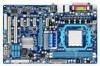
...w 1 x floppy disk drive connector w 1 x IDE connector w 6 x SATA 3Gb/s connectors w 1 x CPU fan header w 2 x system fan headers w 1 x power fan header w 1 x front panel header w 1 x front panel audio header w 1 x CD In connector w 1 x S/PDIF In header w 1 x S/PDIF Out header...Monitor w w w w w w BIOS w w w w System voltage detection CPU/System temperature detection CPU/System/Power fan speed detection CPU overheating warning CPU/System/Power fan fail warning CPU/System fan speed control (Note 4) 2 x 8 Mbit flash Use of licensed AWARD BIOS ...
...w 1 x floppy disk drive connector w 1 x IDE connector w 6 x SATA 3Gb/s connectors w 1 x CPU fan header w 2 x system fan headers w 1 x power fan header w 1 x front panel header w 1 x front panel audio header w 1 x CD In connector w 1 x S/PDIF In header w 1 x S/PDIF Out header...Monitor w w w w w w BIOS w w w w System voltage detection CPU/System temperature detection CPU/System/Power fan speed detection CPU overheating warning CPU/System/Power fan fail warning CPU/System fan speed control (Note 4) 2 x 8 Mbit flash Use of licensed AWARD BIOS ...
Manual
Page 13
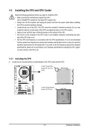
... and thin layer of thermal grease on the surface of the CPU. • Do not turn off the computer and unplug the power cord from the power outlet before you begin to install the CPU: • Make sure that the system bus frequency be inserted if oriented incorrectly. (...Or you wish to set beyond the standard specifications, please do so according to GIGABYTE's website for the peripherals. Hardware Installation 1-3 Installing the CPU and...
... and thin layer of thermal grease on the surface of the CPU. • Do not turn off the computer and unplug the power cord from the power outlet before you begin to install the CPU: • Make sure that the system bus frequency be inserted if oriented incorrectly. (...Or you wish to set beyond the standard specifications, please do so according to GIGABYTE's website for the peripherals. Hardware Installation 1-3 Installing the CPU and...

Manual
Page 14
... correctly install the CPU into the motherboard CPU socket. • Before installing the CPU, make sure to turn off the computer and unplug the power cord from the power outlet to prevent damage to the CPU. • Do not force the CPU into their holes. Step 2: Align the CPU pin one finger...
... correctly install the CPU into the motherboard CPU socket. • Before installing the CPU, make sure to turn off the computer and unplug the power cord from the power outlet to prevent damage to the CPU. • Do not force the CPU into their holes. Step 2: Align the CPU pin one finger...

Manual
Page 15
...on the motherboard. Inadequately removing the CPU cooler may adhere to correctly install the CPU cooler on the CPU. (The following procedure uses the GIGABYTE cooler as the picture above shows) to lock into place. (Refer to your CPU cooler installation manual for instructions on installing the cooler.) Step... 5: Finally, attach the power connector of the CPU cooler to the mounting lug on the surface of the retention frame. Step 2: Place the CPU cooler on the ...
...on the motherboard. Inadequately removing the CPU cooler may adhere to correctly install the CPU cooler on the CPU. (The following procedure uses the GIGABYTE cooler as the picture above shows) to lock into place. (Refer to your CPU cooler installation manual for instructions on installing the cooler.) Step... 5: Finally, attach the power connector of the CPU cooler to the mounting lug on the surface of the retention frame. Step 2: Place the CPU cooler on the ...

Manual
Page 16
Hardware Installation - 16 - Dual Channel mode cannot be used . (Go to GIGABYTE's website for the latest memory support list.) • Always turn off the computer and unplug the power cord from the power outlet before installing the memory to CPU limitations, read the following guidelines before you are divided into two channels and each...
Hardware Installation - 16 - Dual Channel mode cannot be used . (Go to GIGABYTE's website for the latest memory support list.) • Always turn off the computer and unplug the power cord from the power outlet before installing the memory to CPU limitations, read the following guidelines before you are divided into two channels and each...

Manual
Page 17
... can only fit in the memory sockets. 1-4-2 Installing a Memory Before installing a memory module, make sure to turn off the computer and unplug the power cord from the power outlet to prevent damage to correctly install your fingers on the top edge of the memory module. DDR3 and DDR2 DIMMs are not compatible...
... can only fit in the memory sockets. 1-4-2 Installing a Memory Before installing a memory module, make sure to turn off the computer and unplug the power cord from the power outlet to prevent damage to correctly install your fingers on the top edge of the memory module. DDR3 and DDR2 DIMMs are not compatible...

Manual
Page 18
... Express Graphics Card: • Installing a Graphics Card: Gently push down on your expansion card. • Always turn off the computer and unplug the power cord from the power outlet before you begin to prevent hardware damage. Hardware Installation - 18 - Locate an expansion slot that came with the slot, and press down on...
... Express Graphics Card: • Installing a Graphics Card: Gently push down on your expansion card. • Always turn off the computer and unplug the power cord from the power outlet before you begin to prevent hardware damage. Hardware Installation - 18 - Locate an expansion slot that came with the slot, and press down on...

Manual
Page 21
Hardware Installation Unplug the power cord from the power outlet to prevent damage to the devices. • After installing the device and before connecting external devices: • First make sure the device cable has ...
Hardware Installation Unplug the power cord from the power outlet to prevent damage to the devices. • After installing the device and before connecting external devices: • First make sure the device cable has ...

Manual
Page 22
... into pins under the protective cover when using a 2x12 power supply, remove the protective cover from the main power connector on the motherboard. The power connector possesses a foolproof design. The 12V power connector mainly supplies power to the power connector in the correct orientation. When using a 2x10 power supply. 2 1 4 3 ATX_12V ATX_12V: Pin No....4 5 6 7 8 9 10 11 12 Definition Pin No. 3.3V 13 3.3V 14 GND 15 +5V 16 GND 17 +5V 18 GND 19 Power Good 20 5VSB (stand by +5V) 21 +12V 22 +12V (Only for 2x12-pin ATX) 23 3.3V (Only for 2x12-pin ATX) 24 ...
... into pins under the protective cover when using a 2x12 power supply, remove the protective cover from the main power connector on the motherboard. The power connector possesses a foolproof design. The 12V power connector mainly supplies power to the power connector in the correct orientation. When using a 2x10 power supply. 2 1 4 3 ATX_12V ATX_12V: Pin No....4 5 6 7 8 9 10 11 12 Definition Pin No. 3.3V 13 3.3V 14 GND 15 +5V 16 GND 17 +5V 18 GND 19 Power Good 20 5VSB (stand by +5V) 21 +12V 22 +12V (Only for 2x12-pin ATX) 23 3.3V (Only for 2x12-pin ATX) 24 ...

Manual
Page 23
... / SYS_FAN1 / SYS_FAN2 / PWR_FAN (Fan Headers) The motherboard has a 4-pin CPU fan header (CPU_FAN), a 4-pin (SYS_FAN1) and one 3-pin (SYS_ FAN2) system fan headers, and a 3-pin power fan header (PWR_FAN). The motherboard supports CPU fan speed control, which requires the use of floppy disk drives supported are not configuration jumper blocks.
... / SYS_FAN1 / SYS_FAN2 / PWR_FAN (Fan Headers) The motherboard has a 4-pin CPU fan header (CPU_FAN), a 4-pin (SYS_FAN1) and one 3-pin (SYS_ FAN2) system fan headers, and a 3-pin power fan header (PWR_FAN). The motherboard supports CPU fan speed control, which requires the use of floppy disk drives supported are not configuration jumper blocks.

Manual
Page 25
... chassis front panel module to the pin assignments below. The LED is on the chassis front panel. A front panel module mainly consists of power switch, reset switch, power LED, hard drive activity LED, speaker and etc. You may differ by issuing a beep code. The front panel design may configure the... way to turn off (S5). • PW (Power Switch, Red): Connects to the reset switch on when the hard drive is operating. Note the positive and negative pins before connecting the cables. Press...
... chassis front panel module to the pin assignments below. The LED is on the chassis front panel. A front panel module mainly consists of power switch, reset switch, power LED, hard drive activity LED, speaker and etc. You may differ by issuing a beep code. The front panel design may configure the... way to turn off (S5). • PW (Power Switch, Red): Connects to the reset switch on when the hard drive is operating. Note the positive and negative pins before connecting the cables. Press...

Manual
Page 26
... each wire instead of a single plug. Definition 1 MIC2_L Pin No. Definition 1 CD-L 2 GND 3 GND 1 4 CD-R Hardware Installation - 26 - Definition 1 MIC 10 2 2 GND 3 MIC2_R 2 GND 3 MIC Power 4 -ACZ_DET 4 NC 5 LINE2_R 5 Line Out (R) 6 GND 6 NC 7 FAUDIO_JD 7 NC 8 No Pin 8 No Pin 9 LINE2_L 9 Line Out (L) 10 GND 10 NC • The front panel audio...
... each wire instead of a single plug. Definition 1 MIC2_L Pin No. Definition 1 CD-L 2 GND 3 GND 1 4 CD-R Hardware Installation - 26 - Definition 1 MIC 10 2 2 GND 3 MIC2_R 2 GND 3 MIC Power 4 -ACZ_DET 4 NC 5 LINE2_R 5 Line Out (R) 6 GND 6 NC 7 FAUDIO_JD 7 NC 8 No Pin 8 No Pin 9 LINE2_L 9 Line Out (L) 10 GND 10 NC • The front panel audio...

Manual
Page 27
... connecting the S/PDIF digital audio cable, carefully read the manual for digital audio output from the HDMI display at the same time. Pin No. 1 2 3 Definition Power SPDIFI GND 1 13) SPDIF_OUT (S/PDIF Out Header) This header supports digital S/PDIF Out and connects a S/PDIF digital audio cable (provided by expansion cards) for your...
... connecting the S/PDIF digital audio cable, carefully read the manual for digital audio output from the HDMI display at the same time. Pin No. 1 2 3 Definition Power SPDIFI GND 1 13) SPDIF_OUT (S/PDIF Out Header) This header supports digital S/PDIF Out and connects a S/PDIF digital audio cable (provided by expansion cards) for your...

Manual
Page 28
... replaced with an equivalent one minute. (Or use a metal object like a screwdriver to turn off your computer and unplug the power cord from the battery holder and wait for 5 seconds.) 3. Definition 1 Power (5V) 2 Power (5V) 3 USB DX- 9 1 10 2 4 USB DY5 USB DX+ 6 USB DY+ 7 GND 8 GND 9 No Pin ...USB bracket, be sure to touch the positive and negative terminals of explosion if the battery is turned off your computer and unplug the power cord. 2. Danger of the battery holder, making them short for one . Each USB header can provide two USB ports via an ...
... replaced with an equivalent one minute. (Or use a metal object like a screwdriver to turn off your computer and unplug the power cord from the battery holder and wait for 5 seconds.) 3. Definition 1 Power (5V) 2 Power (5V) 3 USB DX- 9 1 10 2 4 USB DY5 USB DX+ 6 USB DY+ 7 GND 8 GND 9 No Pin ...USB bracket, be sure to touch the positive and negative terminals of explosion if the battery is turned off your computer and unplug the power cord. 2. Danger of the battery holder, making them short for one . Each USB header can provide two USB ports via an ...

Manual
Page 29
16) CLR_CMOS (Clearing CMOS Jumper) Use this jumper to remove the jumper cap from the power outlet before clearing the CMOS values. • After clearing the CMOS values and before turning on the two pins to temporarily short the two pins ... a screwdriver to touch the two pins for BIOS configurations). - 29 - Open: Normal Short: Clear CMOS Values • Always turn off your computer and unplug the power cord from the jumper. Failure to do so may cause damage to the motherboard. • After system restart, go to BIOS Setup to load factory...
16) CLR_CMOS (Clearing CMOS Jumper) Use this jumper to remove the jumper cap from the power outlet before clearing the CMOS values. • After clearing the CMOS values and before turning on the two pins to temporarily short the two pins ... a screwdriver to touch the two pins for BIOS configurations). - 29 - Open: Normal Short: Clear CMOS Values • Always turn off your computer and unplug the power cord from the jumper. Failure to do so may cause damage to the motherboard. • After system restart, go to BIOS Setup to load factory...

Manual
Page 31
...of BIOS, it with caution. To see more advanced BIOS Setup menu options, you not flash the BIOS. Its major functions include conducting the Power-On Self-Test (POST) during the POST. Chapter 2 BIOS Setup BIOS (Basic Input and Output System) records hardware parameters of the system in... the CMOS on . To upgrade the BIOS, use either the GIGABYTE Q-Flash or @BIOS utility. • Q-Flash allows the user to quickly and easily upgrade or back up BIOS without entering the operating system. •...
...of BIOS, it with caution. To see more advanced BIOS Setup menu options, you not flash the BIOS. Its major functions include conducting the Power-On Self-Test (POST) during the POST. Chapter 2 BIOS Setup BIOS (Basic Input and Output System) records hardware parameters of the system in... the CMOS on . To upgrade the BIOS, use either the GIGABYTE Q-Flash or @BIOS utility. • Q-Flash allows the user to quickly and easily upgrade or back up BIOS without entering the operating system. •...

Manual
Page 33
...: E1c) CMOS Setup Utility-Copyright (C) 1984-2009 Award Software MB Intelligent Tweaker(M.I.T.) Standard CMOS Features Advanced BIOS Features Integrated Peripherals Power Management Setup PC Health Status Load Fail-Safe Defaults Load Optimized Defaults Set Supervisor Password Set User Password Save & Exit Setup Exit Without Saving...
...: E1c) CMOS Setup Utility-Copyright (C) 1984-2009 Award Software MB Intelligent Tweaker(M.I.T.) Standard CMOS Features Advanced BIOS Features Integrated Peripherals Power Management Setup PC Health Status Load Fail-Safe Defaults Load Optimized Defaults Set Supervisor Password Set User Password Save & Exit Setup Exit Without Saving...


