Manual
Page 1
GA-MA770-DS3/ GA-MA770-S3 AM2+/AM2 socket motherboard for AMD PhenomTM FX processor/ AMD PhenomTM processor/ AMD AthlonTM 64 FX processor/ AMD AthlonTM 64 X2 Dual-Core processor/ AMD AthlonTM 64 processor/AMD SempronTM processor User's Manual Rev. 1003 12ME-MA770S3-1003R
GA-MA770-DS3/ GA-MA770-S3 AM2+/AM2 socket motherboard for AMD PhenomTM FX processor/ AMD PhenomTM processor/ AMD AthlonTM 64 FX processor/ AMD AthlonTM 64 X2 Dual-Core processor/ AMD AthlonTM 64 processor/AMD SempronTM processor User's Manual Rev. 1003 12ME-MA770S3-1003R

Manual
Page 2
Motherboard GA-MA770-DS3/GA-MA770-S3 Nov. 12, 2007 Motherboard GA-MA770-DS3/ GA-MA770-S3 Nov. 12, 2007
Motherboard GA-MA770-DS3/GA-MA770-S3 Nov. 12, 2007 Motherboard GA-MA770-DS3/ GA-MA770-S3 Nov. 12, 2007

Manual
Page 3
.... For product-related information, check on our website at: http://www.gigabyte.com.tw Identifying Your Motherboard Revision The revision number on our website. Check your motherboard looks like this manual are legally registered to GIGABYTE UNITED INC. No part of GIGABYTE branded motherboards. is protected by any form or by copyright laws and is the...
.... For product-related information, check on our website at: http://www.gigabyte.com.tw Identifying Your Motherboard Revision The revision number on our website. Check your motherboard looks like this manual are legally registered to GIGABYTE UNITED INC. No part of GIGABYTE branded motherboards. is protected by any form or by copyright laws and is the...

Manual
Page 4
Table of Contents Box Contents ...6 OptionalItems ...6 GA-MA770-DS3/S3 Motherboard Layout 7 Block Diagram ...8 Chapter 1 Hardware Installation 9 1-1 Installation Precautions 9 1-2 Product Specifications 10 1-3 Installing the CPU and CPU Cooler 13 1-3-1 Installing the CPU 13 1-3-2 Installing the CPU ...
Table of Contents Box Contents ...6 OptionalItems ...6 GA-MA770-DS3/S3 Motherboard Layout 7 Block Diagram ...8 Chapter 1 Hardware Installation 9 1-1 Installation Precautions 9 1-2 Product Specifications 10 1-3 Installing the CPU and CPU Cooler 13 1-3-1 Installing the CPU 13 1-3-2 Installing the CPU ...

Manual
Page 6
...1SPDIN-01R) LPT port cable (Part No. 12CF1-1LP001-01R) - 6 - The box contents are for reference only. Box Contents GA-MA770-DS3 or GA-MA770-S3 motherboard Motherboard driver disk User's Manual Quick Installation Guide One IDE cable and one floppy disk drive cable Two SATA 3Gb/s cables I/O Shield •...; The box contents above are subject to change without notice. • The motherboard image is for reference only ...
...1SPDIN-01R) LPT port cable (Part No. 12CF1-1LP001-01R) - 6 - The box contents are for reference only. Box Contents GA-MA770-DS3 or GA-MA770-S3 motherboard Motherboard driver disk User's Manual Quick Installation Guide One IDE cable and one floppy disk drive cable Two SATA 3Gb/s cables I/O Shield •...; The box contents above are subject to change without notice. • The motherboard image is for reference only ...

Manual
Page 7
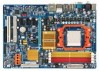
GA-MA770-DS3/S3 Motherboard Layout KB_MS SYS_FAN2 CPU_FAN Socket AM2 RCA_SPDIF ATX COMA USB_1394_1 USB_1394_2 USB_LAN PWR_FAN F_AUDIO GA-MA770-DS3/S3 AUDIO RTL8111B CODEC ATX_12V PCIE_1 NB_FAN PCIE_2 PCIE_3 AMD 770 PCIE_16 DDRII_1 DDRII_2 DDRII_3 DDRII_4 IDE AMD SB600 CD_IN SPDIF_IN SPDIF_OUT PCIE_4 TSB43AB23 PCI1 BAT F_USB1 CLR_CMOS PCI2 F1_1394 FDD F_USB2 SATAII1 SATAII3 SATAII0 SATAII2 IT8718 CI LPT BIOS SYS_FAN1 F_PANEL PWR_LED "*" Only the GA-MA770-DS3 adopts All-Solid Capacitor design. - 7 -
GA-MA770-DS3/S3 Motherboard Layout KB_MS SYS_FAN2 CPU_FAN Socket AM2 RCA_SPDIF ATX COMA USB_1394_1 USB_1394_2 USB_LAN PWR_FAN F_AUDIO GA-MA770-DS3/S3 AUDIO RTL8111B CODEC ATX_12V PCIE_1 NB_FAN PCIE_2 PCIE_3 AMD 770 PCIE_16 DDRII_1 DDRII_2 DDRII_3 DDRII_4 IDE AMD SB600 CD_IN SPDIF_IN SPDIF_OUT PCIE_4 TSB43AB23 PCI1 BAT F_USB1 CLR_CMOS PCI2 F1_1394 FDD F_USB2 SATAII1 SATAII3 SATAII0 SATAII2 IT8718 CI LPT BIOS SYS_FAN1 F_PANEL PWR_LED "*" Only the GA-MA770-DS3 adopts All-Solid Capacitor design. - 7 -

Manual
Page 9
... an ESD wrist strap, keep your hands dry and first touch a metal object to eliminate static electricity. • Prior to installing the motherboard, please have a problem related to wear an electrostatic discharge (ESD) wrist strap when handling electronic components such as a result of the product...technician. - 9 - These stickers are required for warranty validation. • Always remove the AC power by unplugging the power cord from the motherboard, make sure the power supply has been turned off. • Before turning on the power, make sure they are uncertain about any metal ...
... an ESD wrist strap, keep your hands dry and first touch a metal object to eliminate static electricity. • Prior to installing the motherboard, please have a problem related to wear an electrostatic discharge (ESD) wrist strap when handling electronic components such as a result of the product...technician. - 9 - These stickers are required for warranty validation. • Always remove the AC power by unplugging the power cord from the motherboard, make sure the power supply has been turned off. • Before turning on the power, make sure they are uncertain about any metal ...
Manual
Page 10
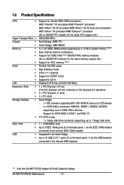
...10 USB 2.0/1.1 ports (6 on the back panel, 4 via the USB brackets connected to the internal USB headers) "*" Only the GA-MA770-DS3 adopts All-Solid Capacitor design. GA-MA770-DS3/S3 Motherboard - 10 - Support for CD In Realtek 8111B chip (10/100/1000 Mbit) 1 x PCI Express x16 slot (The PCI ... 16 GB of system memory (Note 1) Dual channel memory architecture Support for DDR2 1066 (Note 2)/800/667 MHz memory modules (Go to GIGABYTE's website for the latest memory support list.) Support for ECC memory (Note 3) Realtek ALC888 codec High Definition Audio 2/4/5.1/7.1-channel Support for S/PDIF...
...10 USB 2.0/1.1 ports (6 on the back panel, 4 via the USB brackets connected to the internal USB headers) "*" Only the GA-MA770-DS3 adopts All-Solid Capacitor design. GA-MA770-DS3/S3 Motherboard - 10 - Support for CD In Realtek 8111B chip (10/100/1000 Mbit) 1 x PCI Express x16 slot (The PCI ... 16 GB of system memory (Note 1) Dual channel memory architecture Support for DDR2 1066 (Note 2)/800/667 MHz memory modules (Go to GIGABYTE's website for the latest memory support list.) Support for ECC memory (Note 3) Realtek ALC888 codec High Definition Audio 2/4/5.1/7.1-channel Support for S/PDIF...

Manual
Page 12
GA-MA770-DS3/S3 Motherboard - 12 - Unique Features Bundled Software Operating System Form Factor Š Support for @BIOS Š Support for Download Center Š Support for Q-Flash Š Support for ... CPU/system fan speed control function is supported will depend on the CPU/ system cooler you install. (Note 5) Available functions in EasyTune may differ by motherboard model.
GA-MA770-DS3/S3 Motherboard - 12 - Unique Features Bundled Software Operating System Form Factor Š Support for @BIOS Š Support for Download Center Š Support for Q-Flash Š Support for ... CPU/system fan speed control function is supported will depend on the CPU/ system cooler you install. (Note 5) Available functions in EasyTune may differ by motherboard model.

Manual
Page 13
... (denoted by a small triangle) of the Socket AM2 CPU Socket A Small Triangle Marking Denotes CPU Pin One AM2 CPU - 13 - Hardware Installation mended that the motherboard supports the CPU. (Go to GIGABYTE's website for the peripherals.
... (denoted by a small triangle) of the Socket AM2 CPU Socket A Small Triangle Marking Denotes CPU Pin One AM2 CPU - 13 - Hardware Installation mended that the motherboard supports the CPU. (Go to GIGABYTE's website for the peripherals.
Manual
Page 14
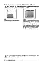
... into the CPU socket. Do not force the CPU into their holes. CPU Socket Locking Lever Step 1: Completely lift up the CPU socket locking lever. GA-MA770-DS3/S3 Motherboard - 14 - The CPU cannot fit in if oriented incorrectly. Once the CPU is positioned into its socket, place one (small triangle marking) with the... it into the fully locked position. Step 2: Align the CPU pin one finger down on the CPU socket and gently insert the CPU into the motherboard CPU socket. Adjust the CPU orientation if this occurs. B. Follow the steps below to the CPU.
... into the CPU socket. Do not force the CPU into their holes. CPU Socket Locking Lever Step 1: Completely lift up the CPU socket locking lever. GA-MA770-DS3/S3 Motherboard - 14 - The CPU cannot fit in if oriented incorrectly. Once the CPU is positioned into its socket, place one (small triangle marking) with the... it into the fully locked position. Step 2: Align the CPU pin one finger down on the CPU socket and gently insert the CPU into the motherboard CPU socket. Adjust the CPU orientation if this occurs. B. Follow the steps below to the CPU.

Manual
Page 15
... the retention frame. 1-3-2 Installing the CPU Cooler Follow the steps below to correctly install the CPU cooler on the CPU. (The following procedure uses the GIGABYTE cooler as the picture above shows) to lock into place. (Refer to your CPU cooler installation manual for instructions on installing the cooler.) Step 5: Finally... cam handle from the left side to the right side (as the example.) Step 1: Apply an even and thin layer of thermal grease on the motherboard. On the other side, push straight down on the the CPU cooler clip to hook it to the CPU.
... the retention frame. 1-3-2 Installing the CPU Cooler Follow the steps below to correctly install the CPU cooler on the CPU. (The following procedure uses the GIGABYTE cooler as the picture above shows) to lock into place. (Refer to your CPU cooler installation manual for instructions on installing the cooler.) Step 5: Finally... cam handle from the left side to the right side (as the example.) Step 1: Apply an even and thin layer of thermal grease on the motherboard. On the other side, push straight down on the the CPU cooler clip to hook it to the CPU.

Manual
Page 16
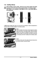
...if only one direction. The four DDR2 memory sockets are unable to install the memory: • Make sure that the motherboard supports the memory. Dual Channel mode cannot be used and installed in the DDRII_1 and DDRII_2 sockets. It is installed, ...Dual Channel Memory Configuration This motherboard provides four DDR2 memory sockets and supports Dual Channel Technology. A memory module can be used . (Go to GIGABYTE's website for optimum performance. When enabling Dual Channel mode with two or four memory modules, it is installed. 2. GA-MA770-DS3/S3 Motherboard - 16 -
...if only one direction. The four DDR2 memory sockets are unable to install the memory: • Make sure that the motherboard supports the memory. Dual Channel mode cannot be used and installed in the DDRII_1 and DDRII_2 sockets. It is installed, ...Dual Channel Memory Configuration This motherboard provides four DDR2 memory sockets and supports Dual Channel Technology. A memory module can be used . (Go to GIGABYTE's website for optimum performance. When enabling Dual Channel mode with two or four memory modules, it is installed. 2. GA-MA770-DS3/S3 Motherboard - 16 -
Manual
Page 17
... memory module is securely inserted. - 17 - Step 1: Note the orientation of the socket will snap into the memory socket. Place the memory module on this motherboard.
... memory module is securely inserted. - 17 - Step 1: Note the orientation of the socket will snap into the memory socket. Place the memory module on this motherboard.

Manual
Page 18
... top edge of the card until it is securely seated in the expansion slot. 1. If necessary, go to BIOS Setup to correctly install your card. GA-MA770-DS3/S3 Motherboard - 18 - Make sure the card is fully inserted into the slot. 4. After installing all expansion cards, replace the chassis cover(s). 6. Carefully read the manual...
... top edge of the card until it is securely seated in the expansion slot. 1. If necessary, go to BIOS Setup to correctly install your card. GA-MA770-DS3/S3 Motherboard - 18 - Make sure the card is fully inserted into the slot. 4. After installing all expansion cards, replace the chassis cover(s). 6. Carefully read the manual...

Manual
Page 19
... transmission or receiving is occurring • When removing the cable connected to an external audio system that your device and then remove it from the motherboard. • When removing the cable, pull it side to side to prevent an electrical short inside the cable connector. - 19 - IEEE 1394a Port The IEEE...
... transmission or receiving is occurring • When removing the cable connected to an external audio system that your device and then remove it from the motherboard. • When removing the cable, pull it side to side to prevent an electrical short inside the cable connector. - 19 - IEEE 1394a Port The IEEE...

Manual
Page 20
... in jack. Mic In Jack (Pink) The default Mic in a 7.1-channel audio configuration. Only microphones still MUST be reconfigured to connect rear speakers in jack ( ). GA-MA770-DS3/S3 Motherboard - 20 - Rear Speaker Out Jack (Black) Use this audio jack to connect front speakers in a 4/5.1/7.1-channel audio configuration. Line Out Jack (Green) The default...
... in jack. Mic In Jack (Pink) The default Mic in a 7.1-channel audio configuration. Only microphones still MUST be reconfigured to connect rear speakers in jack ( ). GA-MA770-DS3/S3 Motherboard - 20 - Rear Speaker Out Jack (Black) Use this audio jack to connect front speakers in a 4/5.1/7.1-channel audio configuration. Line Out Jack (Green) The default...

Manual
Page 21
... 14) SPDIF_IN 15) SPDIF_OUT 16) F_USB1/F_USB2 17) F1_1394 18) LPT 19) BAT 20) CI 21) CLR_CMOS Read the following guidelines before turning on the motherboard. - 21 -
... 14) SPDIF_IN 15) SPDIF_OUT 16) F_USB1/F_USB2 17) F1_1394 18) LPT 19) BAT 20) CI 21) CLR_CMOS Read the following guidelines before turning on the motherboard. - 21 -

Manual
Page 22
... power supply cable into pins under the protective cover when using a 2x12 power supply, remove the protective cover from the main power connector on the motherboard. When using a 2x10 power supply. 3 4 1 2 ATX_12V ATX_12V: Pin No. 1 2 3 4 Definition GND GND +12V +12V 13 1 24 12 ATX ATX: Pin No. 1 2 3 4 5 6 7 8 9... GND PS_ON(soft On/Off) GND GND GND -5V +5V +5V +5V (Only for 2x12-pin ATX) GND (Only for 2x12-pin ATX) GA-MA770-DS3/S3 Motherboard - 22 - If a power supply is used that does not provide the required power, the result can lead to an unstable or unbootable system. ...
... power supply cable into pins under the protective cover when using a 2x12 power supply, remove the protective cover from the main power connector on the motherboard. When using a 2x10 power supply. 3 4 1 2 ATX_12V ATX_12V: Pin No. 1 2 3 4 Definition GND GND +12V +12V 13 1 24 12 ATX ATX: Pin No. 1 2 3 4 5 6 7 8 9... GND PS_ON(soft On/Off) GND GND GND -5V +5V +5V +5V (Only for 2x12-pin ATX) GND (Only for 2x12-pin ATX) GA-MA770-DS3/S3 Motherboard - 22 - If a power supply is used that does not provide the required power, the result can lead to an unstable or unbootable system. ...

Manual
Page 23
...supplies a +12V power voltage and possesses a foolproof insertion design. CPU_FAN: Pin No. Pin No. Hardware Installation 3/4/5) CPU_FAN/SYS_FAN1/SYS_FAN2/PWR_FAN (Fan Headers) The motherboard has a 4-pin CPU fan header (CPU_FAN), a 4-pin (SYS_FAN1) and a 3-pin (SYS_FAN2) system fan header, and a 3-pin power fan header (PWR_FAN... overheating. Do not place a jumper cap on the headers. - 23 - The black connector wire is the ground wire. The motherboard supports CPU fan speed control, which requires the use of a CPU fan with color-coded power connector wires. The black connector wire...
...supplies a +12V power voltage and possesses a foolproof insertion design. CPU_FAN: Pin No. Pin No. Hardware Installation 3/4/5) CPU_FAN/SYS_FAN1/SYS_FAN2/PWR_FAN (Fan Headers) The motherboard has a 4-pin CPU fan header (CPU_FAN), a 4-pin (SYS_FAN1) and a 3-pin (SYS_FAN2) system fan header, and a 3-pin power fan header (PWR_FAN... overheating. Do not place a jumper cap on the headers. - 23 - The black connector wire is the ground wire. The motherboard supports CPU fan speed control, which requires the use of a CPU fan with color-coded power connector wires. The black connector wire...


