
Manual
Page 1
GA-MA770-ES3 AM2+/AM2 socket motherboard for AMD Phenom™ II processor/ AMD Phenom™ processor/ AMD Athlon™ II processor/ AMD Athlon™ processor/ AMD Sempron™ processor User's Manual Rev. 1001 12ME-MA77ES3-1001R
GA-MA770-ES3 AM2+/AM2 socket motherboard for AMD Phenom™ II processor/ AMD Phenom™ processor/ AMD Athlon™ II processor/ AMD Athlon™ processor/ AMD Sempron™ processor User's Manual Rev. 1001 12ME-MA77ES3-1001R

Manual
Page 2
Motherboard GA-MA770-ES3 Feb. 8, 2010 Motherboard GA-MA770-ES3 Feb. 8, 2010
Motherboard GA-MA770-ES3 Feb. 8, 2010 Motherboard GA-MA770-ES3 Feb. 8, 2010

Manual
Page 3
...is 1.0. For instructions on how to their respective owners. Check your motherboard looks like this manual is protected by GIGABYTE without GIGABYTE's prior written permission. Disclaimer Information in any form or by any means without prior notice. For detailed product information... Installation Guide included with the product. Example: Documentation Classifications In order to the specifications and features in the use GIGABYTE's unique features, read or download the information on/from the Support&Downloads\Motherboard\Technology Guide page on your motherboard ...
...is 1.0. For instructions on how to their respective owners. Check your motherboard looks like this manual is protected by GIGABYTE without GIGABYTE's prior written permission. Disclaimer Information in any form or by any means without prior notice. For detailed product information... Installation Guide included with the product. Example: Documentation Classifications In order to the specifications and features in the use GIGABYTE's unique features, read or download the information on/from the Support&Downloads\Motherboard\Technology Guide page on your motherboard ...

Manual
Page 4
Table of Contents Box Contents...6 Optional Items...6 GA-MA770-ES3 Motherboard Layout 7 GA-MA770-ES3 Motherboard Block Diagram 8 Chapter 1 Hardware Installation 9 1-1 Installation Precautions 9 1-2 Product Specifications 10 1-3 Installing the CPU and CPU Cooler 13 1-3-1 Installing the CPU 13 1-3-2 Installing the CPU ...
Table of Contents Box Contents...6 Optional Items...6 GA-MA770-ES3 Motherboard Layout 7 GA-MA770-ES3 Motherboard Block Diagram 8 Chapter 1 Hardware Installation 9 1-1 Installation Precautions 9 1-2 Product Specifications 10 1-3 Installing the CPU and CPU Cooler 13 1-3-1 Installing the CPU 13 1-3-2 Installing the CPU ...

Manual
Page 5
Chapter 3 Drivers Installation 55 3-1 Installing Chipset Drivers 55 3-2 Application Software 56 3-3 Technical Manuals 56 3-4 Contact...57 3-5 System...57 3-6 Download Center 58 Chapter 4 Unique Features 59 4-1 Xpress Recovery2 59 4-2 BIOS Update Utilities 62 4-2-1 Updating the BIOS with the Q-Flash Utility 62 4-2-2 Updating the BIOS with the @BIOS Utility 65 4-3 EasyTune 6...66 4-4 Easy Energy Saver 67 4-5 Q-Share...69 4-6 SMART Recovery 70 Chapter 5 Appendix...71 5-1 Configuring SATA Hard Drive(s 71 5-1-1 Configuring the Onboard SATA Controller 71 5-1-2 Making a SATA RAID/AHCI ...
Chapter 3 Drivers Installation 55 3-1 Installing Chipset Drivers 55 3-2 Application Software 56 3-3 Technical Manuals 56 3-4 Contact...57 3-5 System...57 3-6 Download Center 58 Chapter 4 Unique Features 59 4-1 Xpress Recovery2 59 4-2 BIOS Update Utilities 62 4-2-1 Updating the BIOS with the Q-Flash Utility 62 4-2-2 Updating the BIOS with the @BIOS Utility 65 4-3 EasyTune 6...66 4-4 Easy Energy Saver 67 4-5 Q-Share...69 4-6 SMART Recovery 70 Chapter 5 Appendix...71 5-1 Configuring SATA Hard Drive(s 71 5-1-1 Configuring the Onboard SATA Controller 71 5-1-2 Making a SATA RAID/AHCI ...

Manual
Page 6
...-1FD001-7*R) 2-port USB 2.0 bracket (Part No. 12CR1-1UB030-5*R) 2-port SATA power cable (Part No. 12CF1-2SERPW-0*R) S/PDIF In cable (Part No. 12CR1-1SPDIN-0*R) - 6 - Box Contents GA-MA770-ES3 motherboard Motherboard driver disk User's Manual Quick Installation Guide One IDE cable Two SATA 3Gb/s cables I/O Shield • The box contents above are subject to...
...-1FD001-7*R) 2-port USB 2.0 bracket (Part No. 12CR1-1UB030-5*R) 2-port SATA power cable (Part No. 12CF1-2SERPW-0*R) S/PDIF In cable (Part No. 12CR1-1SPDIN-0*R) - 6 - Box Contents GA-MA770-ES3 motherboard Motherboard driver disk User's Manual Quick Installation Guide One IDE cable Two SATA 3Gb/s cables I/O Shield • The box contents above are subject to...

Manual
Page 7
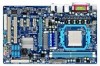
GA-MA770-ES3 Motherboard Layout USB COMA LPT LAN KB(Note)_USB SYS_FAN2 ATX_12V COAXIAL Socket AM2 ATX R_USB AUDIO CPU_FAN F_AUDIO RTL8111D PCIEX1_1 PCIEX16 CODEC PCIEX1_2 PCIEX1_3 SPDIF_IN SPDIF_OUT CD_IN PCIEX1_4 PCI1 IT8720 PCI2 FDD GA-MA770-ES3 AMD 770 DDR2_1 DDR2_2 PWR_FAN IDE M_BIOS AMD SB710 BAT B_BIOS CLR_CMOS SATA2_2 SATA2_5 F_USB2 SATA2_0 SATA2_3 F_PANEL F_USB1 SATA2_1 SATA2_4 SYS_FAN1 (Note) Use this port to connect a PS/2 keyboard or PS/2 mouse. - 7 -
GA-MA770-ES3 Motherboard Layout USB COMA LPT LAN KB(Note)_USB SYS_FAN2 ATX_12V COAXIAL Socket AM2 ATX R_USB AUDIO CPU_FAN F_AUDIO RTL8111D PCIEX1_1 PCIEX16 CODEC PCIEX1_2 PCIEX1_3 SPDIF_IN SPDIF_OUT CD_IN PCIEX1_4 PCI1 IT8720 PCI2 FDD GA-MA770-ES3 AMD 770 DDR2_1 DDR2_2 PWR_FAN IDE M_BIOS AMD SB710 BAT B_BIOS CLR_CMOS SATA2_2 SATA2_5 F_USB2 SATA2_0 SATA2_3 F_PANEL F_USB1 SATA2_1 SATA2_4 SYS_FAN1 (Note) Use this port to connect a PS/2 keyboard or PS/2 mouse. - 7 -

Manual
Page 8
GA-MA770-ES3 Motherboard Block Diagram CPU CLK+/- (200 MHz) PCIe CLK (100 MHz) AM3/AM2+/AM2 CPU DDR2 1200(O.C.)/1066(Note)/800 MHz Dual Channel Memory 1 PCI ...
GA-MA770-ES3 Motherboard Block Diagram CPU CLK+/- (200 MHz) PCIe CLK (100 MHz) AM3/AM2+/AM2 CPU DDR2 1200(O.C.)/1066(Note)/800 MHz Dual Channel Memory 1 PCI ...

Manual
Page 9
ponents such as physical harm to the user. • If you do not allow screws to come in contact with the motherboard circuit or its components. • Make sure there are no leftover screws or metal components placed on the motherboard or within the computer casing. • Do not place the computer system on an uneven surface. • Do not place the computer system in a high-temperature environment. • Turning on the computer power during the installation process can become damaged as a result of your dealer. Hardware Installation Prior to installation, carefully read the ...
ponents such as physical harm to the user. • If you do not allow screws to come in contact with the motherboard circuit or its components. • Make sure there are no leftover screws or metal components placed on the motherboard or within the computer casing. • Do not place the computer system on an uneven surface. • Do not place the computer system in a high-temperature environment. • Turning on the computer power during the installation process can become damaged as a result of your dealer. Hardware Installation Prior to installation, carefully read the ...
Manual
Page 10
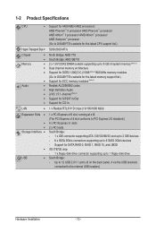
...II processor/ AMD Phenom™ processor/ AMD Athlon™ II processor/ AMD Athlon™ processor/ AMD Sempron™ processor (Go to GIGABYTE's website for the latest CPU support list.) Hyper Transport Bus 5200/2000 MT/s Chipset Memory Audio North Bridge: AMD ...of system memory (Note 1) Dual channel memory architecture Support for DDR2 1200(O.C.)/1066 (Note 2)/800 MHz memory modules (Go to GIGABYTE's website for the latest memory support list.) Support for ECC memory modules (Note 3) Realtek ALC888/892 codec High ...
...II processor/ AMD Phenom™ processor/ AMD Athlon™ II processor/ AMD Athlon™ processor/ AMD Sempron™ processor (Go to GIGABYTE's website for the latest CPU support list.) Hyper Transport Bus 5200/2000 MT/s Chipset Memory Audio North Bridge: AMD ...of system memory (Note 1) Dual channel memory architecture Support for DDR2 1200(O.C.)/1066 (Note 2)/800 MHz memory modules (Go to GIGABYTE's website for the latest memory support list.) Support for ECC memory modules (Note 3) Realtek ALC888/892 codec High ...

Manual
Page 11
Internal Connectors Back Panel Connectors w 1 x 24-pin ATX main power connector w 1 x 4-pin ATX 12V power connector w 1 x floppy disk drive connector w 1 x IDE connector w 6 x SATA 3Gb/s connectors w 1 x CPU fan header w 2 x system fan headers w 1 x power fan header w 1 x front panel header w 1 x front panel audio header w 1 x CD In connector w 1 x S/PDIF In header w 1 x S/PDIF Out header w 2 x USB 2.0/1.1 headers w 1 x clearing CMOS jumper w 1 x PS/2 keyboard port or PS/2 mouse port w 1 x parallel port w 1 x serial port w 1 x coaxial S/PDIF Out connector w 8 x USB 2.0/1.1 ports w 1 ...
Internal Connectors Back Panel Connectors w 1 x 24-pin ATX main power connector w 1 x 4-pin ATX 12V power connector w 1 x floppy disk drive connector w 1 x IDE connector w 6 x SATA 3Gb/s connectors w 1 x CPU fan header w 2 x system fan headers w 1 x power fan header w 1 x front panel header w 1 x front panel audio header w 1 x CD In connector w 1 x S/PDIF In header w 1 x S/PDIF Out header w 2 x USB 2.0/1.1 headers w 1 x clearing CMOS jumper w 1 x PS/2 keyboard port or PS/2 mouse port w 1 x parallel port w 1 x serial port w 1 x coaxial S/PDIF Out connector w 8 x USB 2.0/1.1 ports w 1 ...

Manual
Page 12
Unique Features w w w w w w w w w w Bundled Software w Support for @BIOS Support for Q-Flash Support for Xpress BIOS Rescue Support for Download Center Support for Xpress Install Support for Xpress Recovery2 Support for EasyTune (Note 6) Support for Easy Energy Saver (Note 7) Support for Smart Recovery Support for Q-Share Norton Internet Security (OEM version) Operating System w Support for Microsoft® Windows® 7/Vista/XP Form Factor w ATX Form Factor; 30.5cm x 19cm (Note 1) Due to Windows 32-bit operating system ...
Unique Features w w w w w w w w w w Bundled Software w Support for @BIOS Support for Q-Flash Support for Xpress BIOS Rescue Support for Download Center Support for Xpress Install Support for Xpress Recovery2 Support for EasyTune (Note 6) Support for Easy Energy Saver (Note 7) Support for Smart Recovery Support for Q-Share Norton Internet Security (OEM version) Operating System w Support for Microsoft® Windows® 7/Vista/XP Form Factor w ATX Form Factor; 30.5cm x 19cm (Note 1) Due to Windows 32-bit operating system ...
Manual
Page 13
... even and thin layer of thermal grease on the computer if the CPU cooler is not recommended that the motherboard supports the CPU. (Go to GIGABYTE's website for the peripherals. The CPU cannot be set the frequency beyond hardware specifications since it does not meet the standard requirements for the latest...
... even and thin layer of thermal grease on the computer if the CPU cooler is not recommended that the motherboard supports the CPU. (Go to GIGABYTE's website for the peripherals. The CPU cannot be set the frequency beyond hardware specifications since it does not meet the standard requirements for the latest...

Manual
Page 14
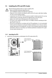
CPU Socket Locking Lever Step 1: Completely lift up the CPU socket locking lever. B. The CPU cannot fit in if oriented incorrectly. Once the CPU is positioned into its socket, place one (small triangle marking) with the triangle mark on the middle of the CPU, lowering the locking lever and latching it into the socket. Adjust the CPU orientation if this occurs. Make sure that the CPU pins fit perfectly into the CPU socket. Follow the steps below to correctly install the CPU into the motherboard CPU socket. • Before installing the CPU, make sure to turn off the computer...
CPU Socket Locking Lever Step 1: Completely lift up the CPU socket locking lever. B. The CPU cannot fit in if oriented incorrectly. Once the CPU is positioned into its socket, place one (small triangle marking) with the triangle mark on the middle of the CPU, lowering the locking lever and latching it into the socket. Adjust the CPU orientation if this occurs. Make sure that the CPU pins fit perfectly into the CPU socket. Follow the steps below to correctly install the CPU into the motherboard CPU socket. • Before installing the CPU, make sure to turn off the computer...

Manual
Page 15
... CPU. Hardware Installation 1-3-2 Installing the CPU Cooler Follow the steps below to correctly install the CPU cooler on the CPU. (The following procedure uses the GIGABYTE cooler as the picture above shows) to lock into place. (Refer to your CPU cooler installation manual for instructions on installing the cooler.) Step 5: Finally...
... CPU. Hardware Installation 1-3-2 Installing the CPU Cooler Follow the steps below to correctly install the CPU cooler on the CPU. (The following procedure uses the GIGABYTE cooler as the picture above shows) to lock into place. (Refer to your CPU cooler installation manual for instructions on installing the cooler.) Step 5: Finally...

Manual
Page 16
A memory module can be used . (Go to GIGABYTE's website for the latest memory support list.) • Always turn off the computer and unplug the power cord from the power outlet before installing the ...
A memory module can be used . (Go to GIGABYTE's website for the latest memory support list.) • Always turn off the computer and unplug the power cord from the power outlet before installing the ...

Manual
Page 17
Follow the steps below to correctly install your fingers on the top edge of the socket will snap into the memory socket. 1-4-2 Installing a Memory Before installing a memory module, make sure to turn off the computer and unplug the power cord from the power outlet to prevent damage to install DDR2 DIMMs on this motherboard. Step 1: Note the orientation of the memory socket. Spread the retaining clips at both ends of the memory module. Hardware Installation As indicated in the picture on the socket. Step 2: The clips at both ends of the memory, push down on the memory and ...
Follow the steps below to correctly install your fingers on the top edge of the socket will snap into the memory socket. 1-4-2 Installing a Memory Before installing a memory module, make sure to turn off the computer and unplug the power cord from the power outlet to prevent damage to install DDR2 DIMMs on this motherboard. Step 1: Note the orientation of the memory socket. Spread the retaining clips at both ends of the memory module. Hardware Installation As indicated in the picture on the socket. Step 2: The clips at both ends of the memory, push down on the memory and ...

Manual
Page 18
Remove the metal slot cover from the power outlet before you begin to make any required BIOS changes for your expansion card(s). 7. Make sure the metal contacts on the card are completely inserted into the PCI Express slot. If necessary, go to BIOS Setup to install an expansion card: • Make sure the motherboard supports the expansion card. Example: Installing and Removing a PCI Express Graphics Card: • Installing a Graphics Card: Gently push down on the card until it is fully seated in your operating system. Make sure the card is fully inserted into the slot. 4. ...
Remove the metal slot cover from the power outlet before you begin to make any required BIOS changes for your expansion card(s). 7. Make sure the metal contacts on the card are completely inserted into the PCI Express slot. If necessary, go to BIOS Setup to install an expansion card: • Make sure the motherboard supports the expansion card. Example: Installing and Removing a PCI Express Graphics Card: • Installing a Graphics Card: Gently push down on the card until it is fully seated in your operating system. Make sure the card is fully inserted into the slot. 4. ...

Manual
Page 19
Parallel Port Use the parallel port to connect devices such as a mouse, modem or other peripherals. Coaxial S/PDIF Out Connector This connector provides digital audio out to connect devices such as a printer, scanner and etc. Serial Port Use the serial port to an external audio system that your audio system provides a coaxial digital audio in connector. PS/2 Keyboard or PS/2 Mouse Port Use this port for USB devices such as a USB keyboard/mouse, USB printer, USB flash drive and etc. RJ-45 LAN Port The Gigabit Ethernet LAN port provides Internet connection at up to...
Parallel Port Use the parallel port to connect devices such as a mouse, modem or other peripherals. Coaxial S/PDIF Out Connector This connector provides digital audio out to connect devices such as a printer, scanner and etc. Serial Port Use the serial port to an external audio system that your audio system provides a coaxial digital audio in connector. PS/2 Keyboard or PS/2 Mouse Port Use this port for USB devices such as a USB keyboard/mouse, USB printer, USB flash drive and etc. RJ-45 LAN Port The Gigabit Ethernet LAN port provides Internet connection at up to...

Manual
Page 20
This jack can be connected to connect front speakers in a 4/5.1-channel audio configuration. Hardware Installation - 20 - Microphones must be used to this jack. Do not rock it side to side to a back panel connector, first remove the cable from your device and then remove it from the motherboard. • When removing the cable, pull it straight out from the connector. Use this audio jack for a headphone or 2-channel speaker. Refer to the instructions on setting up a 2/4/5.1/7.1-channel audio configuration in devices such as an optical drive, walkman, etc. Line Out ...
This jack can be connected to connect front speakers in a 4/5.1-channel audio configuration. Hardware Installation - 20 - Microphones must be used to this jack. Do not rock it side to side to a back panel connector, first remove the cable from your device and then remove it from the motherboard. • When removing the cable, pull it straight out from the connector. Use this audio jack for a headphone or 2-channel speaker. Refer to the instructions on setting up a 2/4/5.1/7.1-channel audio configuration in devices such as an optical drive, walkman, etc. Line Out ...
