Manual
Page 3
... to assist in the use GIGABYTE's unique features, read or download the information on/from the Support&Downloads\Motherboard\Technology Guide page on your motherboard revision before updating motherboard BIOS, drivers, or when looking for technical information. Example: No part of documentations: For detailed product information, carefully read the User's Manual. For instructions on how to the specifications and features in this manual may be reproduced, copied...
... to assist in the use GIGABYTE's unique features, read or download the information on/from the Support&Downloads\Motherboard\Technology Guide page on your motherboard revision before updating motherboard BIOS, drivers, or when looking for technical information. Example: No part of documentations: For detailed product information, carefully read the User's Manual. For instructions on how to the specifications and features in this manual may be reproduced, copied...
Manual
Page 4
... of Contents Box Contents...6 Optional Items...6 GA-MA74GMT-S2H/GA-MA74GMT-S2 Motherboard Layout 7 Block Diagram...8 Chapter 1 Hardware Installation 9 1-1 Installation Precautions 9 1-2 Product Specifications 10 1-3 Installing the CPU and CPU Cooler 13 1-3-1 Installing the CPU 13 1-3-2 Installing the CPU Cooler 15 1-4 Installing the Memory 16 1-4-1 Dual Channel Memory Configuration 16 1-4-2 Installing a Memory 17 1-5 Installing an Expansion Card 18 1-6 Back Panel Connectors 19 1-7 Internal Connectors 21 Chapter 2 BIOS Setup 31 2-1 Startup Screen 32 2-2 The Main Menu 33 2-3 MB...
... of Contents Box Contents...6 Optional Items...6 GA-MA74GMT-S2H/GA-MA74GMT-S2 Motherboard Layout 7 Block Diagram...8 Chapter 1 Hardware Installation 9 1-1 Installation Precautions 9 1-2 Product Specifications 10 1-3 Installing the CPU and CPU Cooler 13 1-3-1 Installing the CPU 13 1-3-2 Installing the CPU Cooler 15 1-4 Installing the Memory 16 1-4-1 Dual Channel Memory Configuration 16 1-4-2 Installing a Memory 17 1-5 Installing an Expansion Card 18 1-6 Back Panel Connectors 19 1-7 Internal Connectors 21 Chapter 2 BIOS Setup 31 2-1 Startup Screen 32 2-2 The Main Menu 33 2-3 MB...
Manual
Page 10
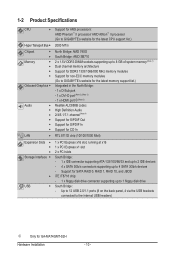
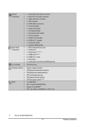
... memory support list.) Integrated in the North Bridge: - 1 x D-Sub port - 1 x DVI-D port (Note 2) (Note 3) - 1 x HDMI port j(Note 3) Realtek ALC888B codec High Definition Audio 2/4/5.1/7.1-channel (Note 4) Support for S/PDIF Out Support for S/PDIF In Support for GA-MA74GMT-S2H Hardware Installation - 10 - Up to 12 USB 2.0/1.1 ports (8 on the back panel, 4 via the USB brackets connected to the internal USB headers) j Only for CD In LAN RTL 8111D chip (10/100/1000 Mbit) Expansion Slots 1 x PCI Express x16 slot...
... memory support list.) Integrated in the North Bridge: - 1 x D-Sub port - 1 x DVI-D port (Note 2) (Note 3) - 1 x HDMI port j(Note 3) Realtek ALC888B codec High Definition Audio 2/4/5.1/7.1-channel (Note 4) Support for S/PDIF Out Support for S/PDIF In Support for GA-MA74GMT-S2H Hardware Installation - 10 - Up to 12 USB 2.0/1.1 ports (8 on the back panel, 4 via the USB brackets connected to the internal USB headers) j Only for CD In LAN RTL 8111D chip (10/100/1000 Mbit) Expansion Slots 1 x PCI Express x16 slot...
Manual
Page 11
Internal Connectors Back Panel Connectors w 1 x 24-pin ATX main power connector w 1 x 4-pin ATX 12V power connector w 1 x floppy disk drive connector w 1 x IDE connector w 4 x SATA 3Gb/s connectors w 1 x CPU fan header w 1 x system fan header w 1 x front panel header w 1 x front panel audio header w 1 x CD In connector w 1 x S/PDIF In/Out header w 2 x USB 2.0/1.1 headers w 1 x serial port header w 1 x clearing CMOS jumper w 1 x PS/2 keyboard/mouse port w 1 x D-Sub port w 1 x DVI-D port (Note 2) (Note 3) w 1 x HDMI portj(Note 3) w 8 x USB 2.0/1.1 ports w 1 x RJ-45 port w ...
Internal Connectors Back Panel Connectors w 1 x 24-pin ATX main power connector w 1 x 4-pin ATX 12V power connector w 1 x floppy disk drive connector w 1 x IDE connector w 4 x SATA 3Gb/s connectors w 1 x CPU fan header w 1 x system fan header w 1 x front panel header w 1 x front panel audio header w 1 x CD In connector w 1 x S/PDIF In/Out header w 2 x USB 2.0/1.1 headers w 1 x serial port header w 1 x clearing CMOS jumper w 1 x PS/2 keyboard/mouse port w 1 x D-Sub port w 1 x DVI-D port (Note 2) (Note 3) w 1 x HDMI portj(Note 3) w 8 x USB 2.0/1.1 ports w 1 x RJ-45 port w ...
Manual
Page 16
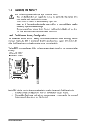
... memory support list.) • Always turn off the computer and unplug the power cord from the power outlet before you are divided into two channels and each channel has one DDR3 memory module is recommended that the motherboard supports the memory. The two DDR3 memory sockets are unable to insert the memory, switch the direction. 1-4-1 Dual Channel Memory Configuration This motherboard provides two DDR3 memory sockets and supports Dual Channel Technology. Dual Channel mode cannot be installed in Dual Channel mode. 1. When enabling Dual Channel mode with two memory...
... memory support list.) • Always turn off the computer and unplug the power cord from the power outlet before you are divided into two channels and each channel has one DDR3 memory module is recommended that the motherboard supports the memory. The two DDR3 memory sockets are unable to insert the memory, switch the direction. 1-4-1 Dual Channel Memory Configuration This motherboard provides two DDR3 memory sockets and supports Dual Channel Technology. Dual Channel mode cannot be installed in Dual Channel mode. 1. When enabling Dual Channel mode with two memory...
Manual
Page 18
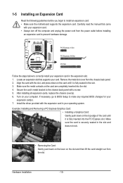
... begin to make any required BIOS changes for your operating system. Turn on the card until it is securely seated in the slot. 3. Install the driver provided with the slot, and press down on the card are completely inserted into the PCI Express slot. After installing all expansion cards, replace the chassis cover(s). 6. Example: Installing and Removing a PCI Express Graphics Card: • Installing a Graphics Card: Gently push down on your card. Make sure the metal contacts...
... begin to make any required BIOS changes for your operating system. Turn on the card until it is securely seated in the slot. 3. Install the driver provided with the slot, and press down on the card are completely inserted into the PCI Express slot. After installing all expansion cards, replace the chassis cover(s). 6. Example: Installing and Removing a PCI Express Graphics Card: • Installing a Graphics Card: Gently push down on your card. Make sure the metal contacts...
Manual
Page 20
... speakers in a 4/5.1-channel audio configuration. Microphones must be used to this audio jack for line in jack. The table below . • CPU: AMD Phenom™ X3 processor or above • Memory: Two 1 GB DDR3 1066 MHz memory modules with dual channel mode enabled • BIOS Setup: At least 256 MB of UMA Frame Buffer Size (refer to Chapter 2, "BIOS Setup," "Advanced BIOS Features," for video output: DVI-D, HDMI and D-Sub. Playback of the LAN port LEDs. Connection/ Speed LED...
... speakers in a 4/5.1-channel audio configuration. Microphones must be used to this audio jack for line in jack. The table below . • CPU: AMD Phenom™ X3 processor or above • Memory: Two 1 GB DDR3 1066 MHz memory modules with dual channel mode enabled • BIOS Setup: At least 256 MB of UMA Frame Buffer Size (refer to Chapter 2, "BIOS Setup," "Advanced BIOS Features," for video output: DVI-D, HDMI and D-Sub. Playback of the LAN port LEDs. Connection/ Speed LED...
Manual
Page 28
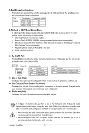
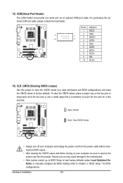
... No Pin 14) CLR_CMOS (Clearing CMOS Jumper) Use this jumper to factory defaults. Failure to do so may cause damage to the motherboard. • After system restart, go to BIOS Setup to load factory defaults (select Load Optimized Defaults) or manually configure the BIOS settings (refer to remove the jumper cap from the power outlet before clearing the CMOS values. • After clearing the CMOS values and before turning on the two pins to temporarily short the two pins or use...
... No Pin 14) CLR_CMOS (Clearing CMOS Jumper) Use this jumper to factory defaults. Failure to do so may cause damage to the motherboard. • After system restart, go to BIOS Setup to load factory defaults (select Load Optimized Defaults) or manually configure the BIOS settings (refer to remove the jumper cap from the power outlet before clearing the CMOS values. • After clearing the CMOS values and before turning on the two pins to temporarily short the two pins or use...
Manual
Page 34
... CPU, memory, etc. Standard CMOS Features Use this menu to configure the system time and date, hard drive types, floppy disk drive types, and the type of errors that stop the system boot, etc. Advanced BIOS Features Use this menu to configure the device boot order, advanced features available on the CPU, and the primary display adapter. Integrated Peripherals Use this menu to configure all peripheral devices, such as IDE, SATA, USB, integrated audio, and integrated LAN, etc. Power Management Setup Use...
... CPU, memory, etc. Standard CMOS Features Use this menu to configure the system time and date, hard drive types, floppy disk drive types, and the type of errors that stop the system boot, etc. Advanced BIOS Features Use this menu to configure the device boot order, advanced features available on the CPU, and the primary display adapter. Integrated Peripherals Use this menu to configure all peripheral devices, such as IDE, SATA, USB, integrated audio, and integrated LAN, etc. Power Management Setup Use...
Manual
Page 36
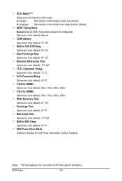
... EC firmware version. (Default) Hybrid Uses the specific AMD EC firmware version. Value (Core 0), Value (Core 1), Value (Core 2), Value (Core 3) This option is configurable only when Advanced Clock Calibration is dependent on the CPU being used. Options are : -12%~+12%. CPU core 2 Enables or disables CPU Core 2. (Default: Enabled) CPU core 3 (Note) Enables or disables CPU Core 3. (Default: Enabled) HT Link Frequency Allows you to alter the North Bridge controller frequency for the settings to be configurable. After the selection, select Save & Exit Setup in the BIOS Main Menu...
... EC firmware version. (Default) Hybrid Uses the specific AMD EC firmware version. Value (Core 0), Value (Core 1), Value (Core 2), Value (Core 3) This option is configurable only when Advanced Clock Calibration is dependent on the CPU being used. Options are : -12%~+12%. CPU core 2 Enables or disables CPU Core 2. (Default: Enabled) CPU core 3 (Note) Enables or disables CPU Core 3. (Default: Enabled) HT Link Frequency Allows you to alter the North Bridge controller frequency for the settings to be configurable. After the selection, select Save & Exit Setup in the BIOS Main Menu...
Manual
Page 37
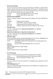
... highly recommended that supports this feature. - 37 - CPU Host Clock Control Enables or disables the control of CPU host clock. Auto sets the PCIe clock frequency to be set the PCIe clock frequency. Manual allows the CPU Frequency (MHz) item below to be configurable. (Default: Auto) Memory Clock This option is configurable only when Set Memory Clock is from 100 MHz to Manual. The adjustable range is from 200 MHz to RAS Delay CKE Power Down Mode [Unganged] [Auto] SPD Auto 9T Auto 9T Auto 9T Auto 24T Auto -- Auto (default) allows the BIOS...
... highly recommended that supports this feature. - 37 - CPU Host Clock Control Enables or disables the control of CPU host clock. Auto sets the PCIe clock frequency to be set the PCIe clock frequency. Manual allows the CPU Frequency (MHz) item below to be configurable. (Default: Auto) Memory Clock This option is configurable only when Set Memory Clock is from 100 MHz to Manual. The adjustable range is from 200 MHz to RAS Delay CKE Power Down Mode [Unganged] [Auto] SPD Auto 9T Auto 9T Auto 9T Auto 24T Auto -- Auto (default) allows the BIOS...
Manual
Page 38
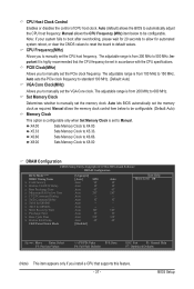
... Options are : Auto (default), 11T~42T. RAS to be configurable. Write Recovery Time Options are : Auto (default), 4T~7T. CKE Power Down Mode Enables or disables the CKE Power Down Mode. (Default: Disabled) (Note) This item appears only if you to single dual-channel. DCTs Mode (Note) Allows you install a CPU that supports this feature. TwTr Command Delay Options are : Auto (default), 5T~12T. Row Precharge Time Options are : Auto (default), 4T~7T. BIOS Setup - 38 - Unganged Sets memory control mode to two single-channel. (Default...
... Options are : Auto (default), 11T~42T. RAS to be configurable. Write Recovery Time Options are : Auto (default), 4T~7T. CKE Power Down Mode Enables or disables the CKE Power Down Mode. (Default: Disabled) (Note) This item appears only if you to single dual-channel. DCTs Mode (Note) Allows you install a CPU that supports this feature. TwTr Command Delay Options are : Auto (default), 5T~12T. Row Precharge Time Options are : Auto (default), 4T~7T. BIOS Setup - 38 - Unganged Sets memory control mode to two single-channel. (Default...
Manual
Page 42
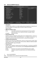
...the list. 2-5 Advanced BIOS Features CMOS Setup Utility-Copyright (C) 1984-2009 Award Software Advanced BIOS Features Virtualization AMD K8 Cool&Quiet control } Hard Disk Boot Priority First Boot Device Second Boot Device Third Boot Device Password Check HDD S.M.A.R.T. Capability Away Mode Backup BIOS Image to HDD Init Display First x Surround View Graphics Display Mode j Internal Graphics Mode Frame Buffer Size Current UMA Size [Enabled] [Auto] [Press Enter] [Floppy] [Hard Disk] [CDROM] [Setup] [Disabled] [Disabled] [Disabled] [PCI Slot...
...the list. 2-5 Advanced BIOS Features CMOS Setup Utility-Copyright (C) 1984-2009 Award Software Advanced BIOS Features Virtualization AMD K8 Cool&Quiet control } Hard Disk Boot Priority First Boot Device Second Boot Device Third Boot Device Password Check HDD S.M.A.R.T. Capability Away Mode Backup BIOS Image to HDD Init Display First x Surround View Graphics Display Mode j Internal Graphics Mode Frame Buffer Size Current UMA Size [Enabled] [Auto] [Press Enter] [Floppy] [Hard Disk] [CDROM] [Setup] [Disabled] [Disabled] [Disabled] [PCI Slot...
Manual
Page 43
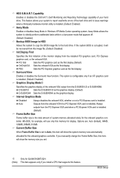
...Internal Graphics Mode Disabled Always disables the onboard VGA, whether or not a PCI Express card is installed. (Default: Enabled) Away Mode Enables or disables Away Mode in a low-power mode that supports this memory for the onboard graphics controller. BIOS Setup This option is configurable only if an ATI graphics card is installed. (Default: Disabled) Graphics Display Modej Specifies the graphics display of the hard drive and to issue warnings when a third party hardware monitor utility is installed. Always outputs from the installed PCI graphics card, PCI...
...Internal Graphics Mode Disabled Always disables the onboard VGA, whether or not a PCI Express card is installed. (Default: Enabled) Away Mode Enables or disables Away Mode in a low-power mode that supports this memory for the onboard graphics controller. BIOS Setup This option is configurable only if an ATI graphics card is installed. (Default: Disabled) Graphics Display Modej Specifies the graphics display of the hard drive and to issue warnings when a third party hardware monitor utility is installed. Always outputs from the installed PCI graphics card, PCI...
Manual
Page 44
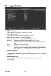
... Native IDE mode. (Default) Enable Native IDE mode if you to decide whether to install operating systems that allows the storage driver to AHCI mode. 2-6 Integrated Peripherals CMOS Setup Utility-Copyright (C) 1984-2009 Award Software Integrated Peripherals OnChip IDE Channel OnChip SATA Controller OnChip SATA Type Onboard LAN Function Onboard LAN Boot ROM } SMART LAN Onboard Audio Function Legacy USB storage detect Onboard Serial Port 1 OnChip USB Controller USB EHCI Controller USB Keyboard Support USB Mouse Support [Enabled] [Enabled...
... Native IDE mode. (Default) Enable Native IDE mode if you to decide whether to install operating systems that allows the storage driver to AHCI mode. 2-6 Integrated Peripherals CMOS Setup Utility-Copyright (C) 1984-2009 Award Software Integrated Peripherals OnChip IDE Channel OnChip SATA Controller OnChip SATA Type Onboard LAN Function Onboard LAN Boot ROM } SMART LAN Onboard Audio Function Legacy USB storage detect Onboard Serial Port 1 OnChip USB Controller USB EHCI Controller USB Keyboard Support USB Mouse Support [Enabled] [Enabled...
Manual
Page 47
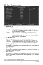
2-7 Power Management Setup CMOS Setup Utility-Copyright (C) 1984-2009 Award Software Power Management Setup ACPI Suspend Type Soft-Off by Power button USB Wake Up from a PCI or PCIe device. The system can be turned off instantly. (Default) Delay 4 Sec. In S3 sleep state, the system appears to be off and consumes less power than 4 seconds, the system will be resumed at least 1A on the +5VSB lead. (Default: Enabled) (Note) Supported on Suspend) sleep state. If...
2-7 Power Management Setup CMOS Setup Utility-Copyright (C) 1984-2009 Award Software Power Management Setup ACPI Suspend Type Soft-Off by Power button USB Wake Up from a PCI or PCIe device. The system can be turned off instantly. (Default) Delay 4 Sec. In S3 sleep state, the system appears to be off and consumes less power than 4 seconds, the system will be resumed at least 1A on the +5VSB lead. (Default: Enabled) (Note) Supported on Suspend) sleep state. If...
Manual
Page 69
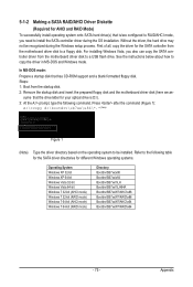
...Then connect the power connector from your computer. Appendix Install SATA hard drive(s) in BIOS Setup. If you do not want to available SATA port on the SATA controller. (Note 2) Required when the SATA controller is recommended that you may prepare only one hard drive. • An empty formatted floppy disk. • Windows Vista/XP setup disk. • Motherboard driver disk. 5-1-1 Configuring the Onboard SATA Controller A. Install the SATA RAID/AHCI driver (Note 2) and operating system. Configuring RAID set to ensure optimal performance, it is set in RAID BIOS. (Note...
...Then connect the power connector from your computer. Appendix Install SATA hard drive(s) in BIOS Setup. If you do not want to available SATA port on the SATA controller. (Note 2) Required when the SATA controller is recommended that you may prepare only one hard drive. • An empty formatted floppy disk. • Windows Vista/XP setup disk. • Motherboard driver disk. 5-1-1 Configuring the Onboard SATA Controller A. Install the SATA RAID/AHCI driver (Note 2) and operating system. Configuring RAID set to ensure optimal performance, it is set in RAID BIOS. (Note...
Manual
Page 75
... formatted floppy disk. Steps: 1: Boot from the motherboard driver disk to be recognized during the OS installation. Refer to copy the driver in MS-DOS and Windows mode. First of all, copy the driver for the SATA controller from the startup disk. 2: Remove the startup disk and insert the prepared floppy disk and the motherboard driver disk (here we as- sume that the drive letter for your optical drive is /are configured to RAID/AHCI mode, you...
... formatted floppy disk. Steps: 1: Boot from the motherboard driver disk to be recognized during the OS installation. Refer to copy the driver in MS-DOS and Windows mode. First of all, copy the driver for the SATA controller from the startup disk. 2: Remove the startup disk and insert the prepared floppy disk and the motherboard driver disk (here we as- sume that the drive letter for your optical drive is /are configured to RAID/AHCI mode, you...
Manual
Page 77
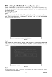
... or RAID driver. Appendix The followings are ready to install Windows Vista/ XP onto your system to boot from the following list, or press ESC to return to continue the driver installation. 5-1-3 Installing the SATA RAID/AHCI Driver and Operating System With the SATA RAID/AHCI driver diskette and correct BIOS settings, you are examples of Windows XP and Vista installation on the AMD SB750 SATA controller. Windows Setup Press F6 if you can pro- ceed with Windows, using a device support disk...
... or RAID driver. Appendix The followings are ready to install Windows Vista/ XP onto your system to boot from the following list, or press ESC to return to continue the driver installation. 5-1-3 Installing the SATA RAID/AHCI Driver and Operating System With the SATA RAID/AHCI driver diskette and correct BIOS settings, you are examples of Windows XP and Vista installation on the AMD SB750 SATA controller. Windows Setup Press F6 if you can pro- ceed with Windows, using a device support disk...
Manual
Page 89
... internal amplifier. A: The following Award BIOS beep code descriptions may help you identify possible computer problems. (For reference only.) 1 short: System boots successfully 1 long, 3 short: Keyboard error 2 short: CMOS setting error 1 long, 9 short: BIOS ROM error 1 long, 1 short: Memory or motherboard error Continuous long beeps: Graphics card not inserted properly 1 long, 2 short: Monitor or graphics card error Continuous short beeps: Power error - 89 - Then install the onboard HD audio driver from the motherboard driver disk or download the audio driver from GIGABYTE...
... internal amplifier. A: The following Award BIOS beep code descriptions may help you identify possible computer problems. (For reference only.) 1 short: System boots successfully 1 long, 3 short: Keyboard error 2 short: CMOS setting error 1 long, 9 short: BIOS ROM error 1 long, 1 short: Memory or motherboard error Continuous long beeps: Graphics card not inserted properly 1 long, 2 short: Monitor or graphics card error Continuous short beeps: Power error - 89 - Then install the onboard HD audio driver from the motherboard driver disk or download the audio driver from GIGABYTE...


