
Manual
Page 8
Block Diagram PCIe CLK (100 MHz) 1 PCI Express x16 AM3/AM2+/AM2 CPU CPU CLK+/- (200 MHz) DDR2 1066/800/667/533 MHz Dual Channel Memory Hyper Transport Bus PCI Express x16 GFX CLK (100 MHz) PCI Express Bus x1 PCIe CLK (100 ... BIOS Floppy COM Port 2 PCI PS/2 KB or Mouse MIC Line Out Line In S/PDIF In S/PDIF Out PCI CLK (33 MHz) j (Note) Only for GA-MA74GM-S2H Simultaneous output for DVI-D and HDMI is not supported. - 8 -
Block Diagram PCIe CLK (100 MHz) 1 PCI Express x16 AM3/AM2+/AM2 CPU CPU CLK+/- (200 MHz) DDR2 1066/800/667/533 MHz Dual Channel Memory Hyper Transport Bus PCI Express x16 GFX CLK (100 MHz) PCI Express Bus x1 PCIe CLK (100 ... BIOS Floppy COM Port 2 PCI PS/2 KB or Mouse MIC Line Out Line In S/PDIF In S/PDIF Out PCI CLK (33 MHz) j (Note) Only for GA-MA74GM-S2H Simultaneous output for DVI-D and HDMI is not supported. - 8 -

Manual
Page 10
...™ processor/ AMD Athlon™ II processor/ AMD Athlon™ processor/ AMD Sempron™ processor (Go to GIGABYTE's website for the latest CPU support list.) Hyper Transport Bus 2000 MT/s Chipset Memory...up to 8 GB of system memory (Note 1) Dual channel memory architecture Support for DDR2 1066/800/667/533 MHz memory modules Support for non-ECC memory modules (Go to GIGABYTE's website for the latest memory support list.) Integrated in the North Bridge: - 1... connected to 4 SATA 3Gb/s devices - Support for GA-MA74GM-S2H Hardware Installation - 10 -
...™ processor/ AMD Athlon™ II processor/ AMD Athlon™ processor/ AMD Sempron™ processor (Go to GIGABYTE's website for the latest CPU support list.) Hyper Transport Bus 2000 MT/s Chipset Memory...up to 8 GB of system memory (Note 1) Dual channel memory architecture Support for DDR2 1066/800/667/533 MHz memory modules Support for non-ECC memory modules (Go to GIGABYTE's website for the latest memory support list.) Integrated in the North Bridge: - 1... connected to 4 SATA 3Gb/s devices - Support for GA-MA74GM-S2H Hardware Installation - 10 -
Manual
Page 16
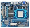
... memory module can be used . (Go to GIGABYTE's website for the latest memory support list.) •...chips be enabled if only one direction. It is recommended that the motherboard supports the memory. The two DDR2 memory sockets are divided into two channels as following: Channel 0: DDR2_1 Channel 1: DDR2_2 DDR2_1 DDR2_2 Due...If you begin to insert the memory, switch the direction. 1-4-1 Dual Channel Memory Configuration This motherboard provides two DDR2 memory sockets and supports Dual Channel Technology. Hardware Installation - 16 - Dual Channel mode cannot be used . ...
... memory module can be used . (Go to GIGABYTE's website for the latest memory support list.) •...chips be enabled if only one direction. It is recommended that the motherboard supports the memory. The two DDR2 memory sockets are divided into two channels as following: Channel 0: DDR2_1 Channel 1: DDR2_2 DDR2_1 DDR2_2 Due...If you begin to insert the memory, switch the direction. 1-4-1 Dual Channel Memory Configuration This motherboard provides two DDR2 memory sockets and supports Dual Channel Technology. Hardware Installation - 16 - Dual Channel mode cannot be used . ...

Manual
Page 17
...inserted. - 17 - Step 2: The clips at both ends of the memory, push down on the socket. Step 1: Note the orientation of the memory socket. DDR2 DIMMs are not compatible to DDR DIMMs. Be sure to correctly install your fingers on the top edge of the socket will snap into the... left, place your memory modules in one direction. Spread the retaining clips at both ends of the memory module. Follow the steps below to install DDR2 DIMMs on this motherboard. 1-4-2 Installing a Memory Before installing a memory module , make sure to turn off the computer and unplug the power cord from ...
...inserted. - 17 - Step 2: The clips at both ends of the memory, push down on the socket. Step 1: Note the orientation of the memory socket. DDR2 DIMMs are not compatible to DDR DIMMs. Be sure to correctly install your fingers on the top edge of the socket will snap into the... left, place your memory modules in one direction. Spread the retaining clips at both ends of the memory module. Follow the steps below to install DDR2 DIMMs on this motherboard. 1-4-2 Installing a Memory Before installing a memory module , make sure to turn off the computer and unplug the power cord from ...
Manual
Page 20
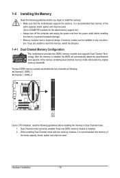
... it straight out from the connector. Hardware Installation - 20 - A. The table below . • CPU: AMD Phenom™ X3 processor or above • Memory: Two 1 GB DDR2 800 MHz memory modules with dual channel mode enabled • BIOS Setup: At least 256 MB of the LAN port LEDs. Refer to the instructions...
... it straight out from the connector. Hardware Installation - 20 - A. The table below . • CPU: AMD Phenom™ X3 processor or above • Memory: Two 1 GB DDR2 800 MHz memory modules with dual channel mode enabled • BIOS Setup: At least 256 MB of the LAN port LEDs. Refer to the instructions...
Manual
Page 35
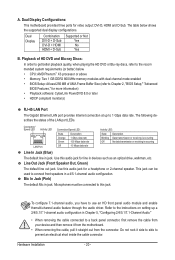
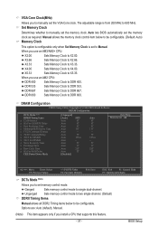
.... (Note) CPU Host Clock Control x CPU Frequency(MHz) PCIE Clock(MHz) VGA Core Clock(MHz) Set Memory Clock x Memory Clock } DRAM Configuration System Voltage Control x DDR2 Voltage Control x NorthBridge Volt Control x SouthBridge Volt Control x CPU NB VID Control x CPU Voltage Control Normal CPU Vcore [Press Enter] [Auto] [Auto] [Auto] [Auto] 200...
.... (Note) CPU Host Clock Control x CPU Frequency(MHz) PCIE Clock(MHz) VGA Core Clock(MHz) Set Memory Clock x Memory Clock } DRAM Configuration System Voltage Control x DDR2 Voltage Control x NorthBridge Volt Control x SouthBridge Volt Control x CPU NB VID Control x CPU Voltage Control Normal CPU Vcore [Press Enter] [Auto] [Auto] [Auto] [Auto] 200...
Manual
Page 37
...+ CPU: X2.00 Sets Memory Clock to be configurable. Unganged Sets memory control mode to two single-channel. (Default) DDRII Timing Items Manual allows all DDR2 Timing items below to X2.00. Manual allows the memory clock control item below to be configurable. (Default: Auto) Memory Clock This option is configurable...
...+ CPU: X2.00 Sets Memory Clock to be configurable. Unganged Sets memory control mode to two single-channel. (Default) DDRII Timing Items Manual allows all DDR2 Timing items below to X2.00. Manual allows the memory clock control item below to be configurable. (Default: Auto) Memory Clock This option is configurable...
Manual
Page 39
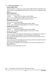
... ******** System Voltage Control Determines whether to manually set the system voltages as required. Manual allows all voltage control items below to be configurable. (Default: Manual) DDR2 Voltage Control Allows you to set memory voltage. Note: Increasing memory voltage may result in damage to 0.3V at 0.1V increment. Auto sets the CPU...
... ******** System Voltage Control Determines whether to manually set the system voltages as required. Manual allows all voltage control items below to be configurable. (Default: Manual) DDR2 Voltage Control Allows you to set memory voltage. Note: Increasing memory voltage may result in damage to 0.3V at 0.1V increment. Auto sets the CPU...

Manual
Page 50
... Status CMOS Setup Utility-Copyright (C) 1984-2009 Award Software PC Health Status Reset Case Open Status Case Opened Vcore DDR2 1.8V +3.3V +12V Current System Temperature Current CPU Temperature Current CPU FAN Speed Current SYSTEM FAN Speed CPU Warning... temperature exceeds the threshold, BIOS will show "No". Current System/CPU Temperature Displays current system/CPU temperature. Current Voltage(V) Vcore/DDR2 1.8V/+3.3V/+12V Displays the current system voltages. CPU Warning Temperature Sets the warning threshold for CPU temperature. Check the fan ...
... Status CMOS Setup Utility-Copyright (C) 1984-2009 Award Software PC Health Status Reset Case Open Status Case Opened Vcore DDR2 1.8V +3.3V +12V Current System Temperature Current CPU Temperature Current CPU FAN Speed Current SYSTEM FAN Speed CPU Warning... temperature exceeds the threshold, BIOS will show "No". Current System/CPU Temperature Displays current system/CPU temperature. Current Voltage(V) Vcore/DDR2 1.8V/+3.3V/+12V Displays the current system voltages. CPU Warning Temperature Sets the warning threshold for CPU temperature. Check the fan ...

