Manual
Page 4
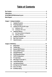
Table of Contents Box Contents ...6 OptionalItems ...6 GA-M78SM-S2H Motherboard Layout 7 Block Diagram ...8 Chapter 1 Hardware Installation 9 1-1 Installation Precautions 9 1-2 Product Specifications 10 1-3 Installing the CPU and CPU Cooler 12 1-3-1 Installing the CPU 12 1-3-2 Installing the CPU Cooler 14 1-4 Installing the Memory 15 1-4-1 Dual Channel Memory Configuration 15 1-4-2 Installing a Memory 16 1-5 Installing an Expansion Card 17 1-6 Back Panel Connectors 18 1-7 Internal Connectors 21 Chapter...
Table of Contents Box Contents ...6 OptionalItems ...6 GA-M78SM-S2H Motherboard Layout 7 Block Diagram ...8 Chapter 1 Hardware Installation 9 1-1 Installation Precautions 9 1-2 Product Specifications 10 1-3 Installing the CPU and CPU Cooler 12 1-3-1 Installing the CPU 12 1-3-2 Installing the CPU Cooler 14 1-4 Installing the Memory 15 1-4-1 Dual Channel Memory Configuration 15 1-4-2 Installing a Memory 16 1-5 Installing an Expansion Card 17 1-6 Back Panel Connectors 18 1-7 Internal Connectors 21 Chapter...
Manual
Page 5
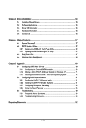
Chapter 3 Drivers Installation 53 3-1 Installing Chipset Drivers 53 3-2 SoftwareApplications 54 3-3 Driver CD Information 54 3-4 Hardware Information 55 3-5 Contact Us ...55 Chapter 4 Unique Features 57 4-1 Xpress ... Onboard SATA Controller 69 5-1-2 Making a SATA RAID/AHCI Driver Diskette for Windows XP 74 5-1-3 Installing the SATA RAID/AHCI Driver and Operating System 75 5-2 ConfiguringAudio Input and Output 81 5-2-1 Configuring 2/4/5.1/7.1-Channel Audio 81 5-2-2 Installing the S/PDIF Out Cable (Optional 84 5-2-3 Configuring Microphone Recording 86 5-2-4 Using the Sound Recorder ...
Chapter 3 Drivers Installation 53 3-1 Installing Chipset Drivers 53 3-2 SoftwareApplications 54 3-3 Driver CD Information 54 3-4 Hardware Information 55 3-5 Contact Us ...55 Chapter 4 Unique Features 57 4-1 Xpress ... Onboard SATA Controller 69 5-1-2 Making a SATA RAID/AHCI Driver Diskette for Windows XP 74 5-1-3 Installing the SATA RAID/AHCI Driver and Operating System 75 5-2 ConfiguringAudio Input and Output 81 5-2-1 Configuring 2/4/5.1/7.1-Channel Audio 81 5-2-2 Installing the S/PDIF Out Cable (Optional 84 5-2-3 Configuring Microphone Recording 86 5-2-4 Using the Sound Recorder ...
Manual
Page 9
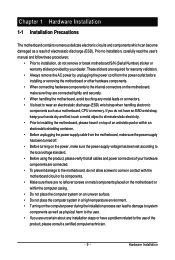
... have an ESD wrist strap, keep your hands dry and first touch a metal object to eliminate static electricity. • Prior to installing the motherboard, please have a problem related to come in contact with the motherboard circuit or its components. • Make sure there are...placed on the motherboard or within an electrostatic shielding container. • Before unplugging the power supply cable from the power outlet before installing or removing the motherboard or other hardware components. • When connecting hardware components to the internal connectors on the motherboard, make...
... have an ESD wrist strap, keep your hands dry and first touch a metal object to eliminate static electricity. • Prior to installing the motherboard, please have a problem related to come in contact with the motherboard circuit or its components. • Make sure there are...placed on the motherboard or within an electrostatic shielding container. • Before unplugging the power supply cable from the power outlet before installing or removing the motherboard or other hardware components. • When connecting hardware components to the internal connectors on the motherboard, make...
Manual
Page 11
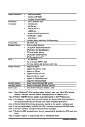
...; Support for @BIOS Š Support for Download Center Š Support for Q-Flash Š Support for EasyTune (Note 8) Š Support for Xpress Install Š Support for Xpress Recovery2 Š Support for Virtual Dual BIOS Bundled Software Š Norton Internet Security (OEM version) Operating System Š Support...Factor; 24.4cm x 21cm (Note 1) Due to Windows XP 32-bit operating system limitation, when more than 4 GB of physical memory is installed, the actual memory size displayed will be less than 4 GB. (Note 2) Whether 1066 MHz memory speed is supported depends on the CPU being...
...; Support for @BIOS Š Support for Download Center Š Support for Q-Flash Š Support for EasyTune (Note 8) Š Support for Xpress Install Š Support for Xpress Recovery2 Š Support for Virtual Dual BIOS Bundled Software Š Norton Internet Security (OEM version) Operating System Š Support...Factor; 24.4cm x 21cm (Note 1) Due to Windows XP 32-bit operating system limitation, when more than 4 GB of physical memory is installed, the actual memory size displayed will be less than 4 GB. (Note 2) Whether 1066 MHz memory speed is supported depends on the CPU being...
Manual
Page 12
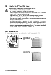
...if the CPU cooler is not recom- mended that the motherboard supports the CPU. (Go to GIGABYTE's website for the peripherals. 1-3 Installing the CPU and CPU Cooler Read the following guidelines before installing the CPU to prevent hardware damage. • Locate the pin one (denoted by a small ... begin to install the CPU: • Make sure that the system bus frequency be inserted if oriented incorrectly. • Apply an even and thin layer of thermal grease on the surface of the Socket AM2 Socket A Small Triangle Marking Denotes CPU Pin One AM2+/AM2 CPU GA-M78SM-S2H Motherboard -...
...if the CPU cooler is not recom- mended that the motherboard supports the CPU. (Go to GIGABYTE's website for the peripherals. 1-3 Installing the CPU and CPU Cooler Read the following guidelines before installing the CPU to prevent hardware damage. • Locate the pin one (denoted by a small ... begin to install the CPU: • Make sure that the system bus frequency be inserted if oriented incorrectly. • Apply an even and thin layer of thermal grease on the surface of the Socket AM2 Socket A Small Triangle Marking Denotes CPU Pin One AM2+/AM2 CPU GA-M78SM-S2H Motherboard -...
Manual
Page 13
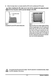
... CPU, make sure to turn off the computer and unplug the power cord from the power outlet to prevent damage to correctly install the CPU into the fully locked position. B. CPU Socket Locking Lever Step 1: Completely lift up the CPU socket locking lever. Step 2: Align the CPU pin ... triangle marking) with the triangle mark on the middle of the CPU, lowering the locking lever and latching it into the motherboard CPU socket. Hardware Installation Adjust the CPU orientation if this occurs. - 13 - The CPU cannot fit in if oriented incorrectly.
... CPU, make sure to turn off the computer and unplug the power cord from the power outlet to prevent damage to correctly install the CPU into the fully locked position. B. CPU Socket Locking Lever Step 1: Completely lift up the CPU socket locking lever. Step 2: Align the CPU pin ... triangle marking) with the triangle mark on the middle of the CPU, lowering the locking lever and latching it into the motherboard CPU socket. Hardware Installation Adjust the CPU orientation if this occurs. - 13 - The CPU cannot fit in if oriented incorrectly.
Manual
Page 14
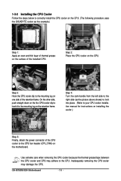
...steps below to the mounting lug on one side of the retention frame. Step 3: Hook the CPU cooler clip to correctly install the CPU cooler on the CPU. (The following procedure uses the GIGABYTE cooler as the picture above shows) to lock into place. (Refer to your CPU cooler... clip to hook it to the mounting lug on the CPU. GA-M78SM-S2H Motherboard - 14 - Inadequately removing the CPU cooler may adhere to the CPU fan header (CPU_FAN) on installing the cooler.) Step 5: Finally, attach the power connector of the installed CPU. Step 2: Place the CPU cooler on the retention frame....
...steps below to the mounting lug on one side of the retention frame. Step 3: Hook the CPU cooler clip to correctly install the CPU cooler on the CPU. (The following procedure uses the GIGABYTE cooler as the picture above shows) to lock into place. (Refer to your CPU cooler... clip to hook it to the mounting lug on the CPU. GA-M78SM-S2H Motherboard - 14 - Inadequately removing the CPU cooler may adhere to the CPU fan header (CPU_FAN) on installing the cooler.) Step 5: Finally, attach the power connector of the installed CPU. Step 2: Place the CPU cooler on the retention frame....
Manual
Page 15
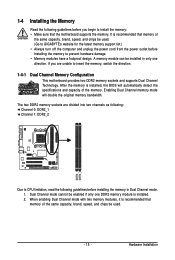
...of the memory. Dual Channel mode cannot be used . (Go to GIGABYTE's website for the latest memory support list.) • Always turn off the computer and unplug the power cord from the power outlet before installing the memory to insert the memory, switch the direction. 1-4-1 Dual Channel... is recommended that memory of the same capacity, brand, speed, and chips be installed in Dual Channel mode. 1. After the memory is recommended that the motherboard supports the memory. It is installed, the BIOS will double the original memory bandwidth. The two DDR2 memory sockets are...
...of the memory. Dual Channel mode cannot be used . (Go to GIGABYTE's website for the latest memory support list.) • Always turn off the computer and unplug the power cord from the power outlet before installing the memory to insert the memory, switch the direction. 1-4-1 Dual Channel... is recommended that memory of the same capacity, brand, speed, and chips be installed in Dual Channel mode. 1. After the memory is recommended that the motherboard supports the memory. It is installed, the BIOS will double the original memory bandwidth. The two DDR2 memory sockets are...
Manual
Page 16
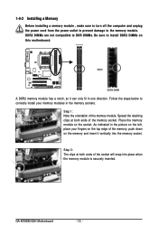
...in one direction. DDR2 DIMMs are not compatible to DDR DIMMs. Be sure to install DDR2 DIMMs on the socket. Spread the retaining clips at both ends of the socket will snap into the memory socket. GA-M78SM-S2H Motherboard - 16 - Step 1: Note the orientation of the memory, push down.... Notch DDR2 DIMM A DDR2 memory module has a notch, so it vertically into place when the memory module is securely inserted. 1-4-2 Installing a Memory Before installing a memory module , make sure to turn off the computer and unplug the power cord from the power outlet to prevent damage to correctly...
...in one direction. DDR2 DIMMs are not compatible to DDR DIMMs. Be sure to install DDR2 DIMMs on the socket. Spread the retaining clips at both ends of the socket will snap into the memory socket. GA-M78SM-S2H Motherboard - 16 - Step 1: Note the orientation of the memory, push down.... Notch DDR2 DIMM A DDR2 memory module has a notch, so it vertically into place when the memory module is securely inserted. 1-4-2 Installing a Memory Before installing a memory module , make sure to turn off the computer and unplug the power cord from the power outlet to prevent damage to correctly...
Manual
Page 17
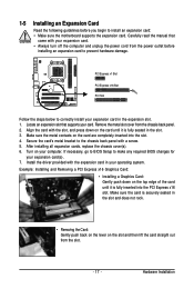
...: • Make sure the motherboard supports the expansion card. Align the card with your expansion card(s). 7. Example: Installing and Removing a PCI Express x16 Graphics Card: • Installing a Graphics Card: Gently push down on the slot and then lift the card straight out from the slot. - 17... - Secure the card's metal bracket to the chassis back panel with the expansion card in the expansion slot. 1. After installing all expansion cards, replace the chassis cover(s). 6. If necessary, go to BIOS Setup to make any required BIOS changes for your expansion card....
...: • Make sure the motherboard supports the expansion card. Align the card with your expansion card(s). 7. Example: Installing and Removing a PCI Express x16 Graphics Card: • Installing a Graphics Card: Gently push down on the slot and then lift the card straight out from the slot. - 17... - Secure the card's metal bracket to the chassis back panel with the expansion card in the expansion slot. 1. After installing all expansion cards, replace the chassis cover(s). 6. If necessary, go to BIOS Setup to make any required BIOS changes for your expansion card....
Manual
Page 18
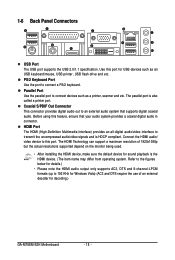
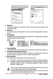
... DTS and 8-channel-LPCM formats (up to transmit the uncompressed audio/video signals and is HDCP compliant. Refer to the figures below for decoding.) GA-M78SM-S2H Motherboard - 18 - 1-6 Back Panel Connectors USB Port The USB port supports the USB 2.0/1.1 specification. The parallel port is the HDMI device. ... Vista) (AC3 and DTS require the use of 1920x1080p but the actual resolutions supported depend on the monitor being used. • After installing the HDMI device, make sure the default device for USB devices such as a printer, scanner and etc. PS/2 Keyboard Port Use the...
... DTS and 8-channel-LPCM formats (up to transmit the uncompressed audio/video signals and is HDCP compliant. Refer to the figures below for decoding.) GA-M78SM-S2H Motherboard - 18 - 1-6 Back Panel Connectors USB Port The USB port supports the USB 2.0/1.1 specification. The parallel port is the HDMI device. ... Vista) (AC3 and DTS require the use of 1920x1080p but the actual resolutions supported depend on the monitor being used. • After installing the HDMI device, make sure the default device for USB devices such as a printer, scanner and etc. PS/2 Keyboard Port Use the...
Manual
Page 19
... HDMI Audio. D-Sub Port The D-Sub port supports a 15-pin D-Sub connector. Line Out Jack (Front Speaker Out, Green) The default line out jack. Hardware Installation In Windows Vista, select Start>Control Panel> Sound, select NVIDIA HDMI Output and then click Set Default. Use this jack. Refer to this audio jack...
... HDMI Audio. D-Sub Port The D-Sub port supports a 15-pin D-Sub connector. Line Out Jack (Front Speaker Out, Green) The default line out jack. Hardware Installation In Windows Vista, select Start>Control Panel> Sound, select NVIDIA HDMI Output and then click Set Default. Use this jack. Refer to this audio jack...
Manual
Page 21
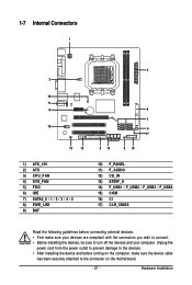
... device and before connecting external devices: • First make sure your devices are compliant with the connectors you wish to connect. • Before installing the devices, be sure to the connector on the computer, make sure the device cable has been securely attached to turn off the devices and ...) CD_IN 13) SPDIF_O 14) F_USB1 / F_USB2 / F_USB3 / F_USB4 15) COM 16) CI 17) CLR_CMOS Read the following guidelines before turning on the motherboard. - 21 - Hardware Installation
... device and before connecting external devices: • First make sure your devices are compliant with the connectors you wish to connect. • Before installing the devices, be sure to the connector on the computer, make sure the device cable has been securely attached to turn off the devices and ...) CD_IN 13) SPDIF_O 14) F_USB1 / F_USB2 / F_USB3 / F_USB4 15) COM 16) CI 17) CLR_CMOS Read the following guidelines before turning on the motherboard. - 21 - Hardware Installation
Manual
Page 22
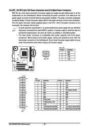
... -12V GND PS_ON(soft On/Off) GND GND GND -5V +5V +5V +5V (Only for 2x12-pin ATX) GND (Only for 2x12-pin ATX) GA-M78SM-S2H Motherboard - 22 - If the 12V power connector is not connected, the computer will not start. • To meet expansion requirements, it is turned off and... withstand high power consumption be used that does not provide the required power, the result can supply enough stable power to all devices are properly installed. Connect the power supply cable to the power connector in the correct orientation. 1/2) ATX_12V/ATX (2x2 12V Power Connector and 2x12 Main Power ...
... -12V GND PS_ON(soft On/Off) GND GND GND -5V +5V +5V +5V (Only for 2x12-pin ATX) GND (Only for 2x12-pin ATX) GA-M78SM-S2H Motherboard - 22 - If the 12V power connector is not connected, the computer will not start. • To meet expansion requirements, it is turned off and... withstand high power consumption be used that does not provide the required power, the result can supply enough stable power to all devices are properly installed. Connect the power supply cable to the power connector in the correct orientation. 1/2) ATX_12V/ATX (2x2 12V Power Connector and 2x12 Main Power ...
Manual
Page 23
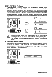
... Most fans are designed with fan speed control design. For optimum heat dissipation, it in damage to connect a floppy disk drive. Hardware Installation 3/4) CPU_FAN/SYS_FAN (Fan Headers) The motherboard has a 4-pin CPU fan header (CPU_FAN) and a 3-pin system fan header (SYS_FAN...is typically designated by a stripe of floppy disk drives supported are not configuration jumper blocks. Before connecting a floppy disk drive, be installed inside the chassis. Each fan header supplies a +12V power voltage and possesses a foolproof insertion design. When connecting a fan cable,...
... Most fans are designed with fan speed control design. For optimum heat dissipation, it in damage to connect a floppy disk drive. Hardware Installation 3/4) CPU_FAN/SYS_FAN (Fan Headers) The motherboard has a 4-pin CPU fan header (CPU_FAN) and a 3-pin system fan header (SYS_FAN...is typically designated by a stripe of floppy disk drives supported are not configuration jumper blocks. Before connecting a floppy disk drive, be installed inside the chassis. Each fan header supplies a +12V power voltage and possesses a foolproof insertion design. When connecting a fan cable,...
Manual
Page 25
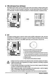
...the battery is replaced with an incorrect model. • Contact the place of the battery holder, making them short for one . Pin No. Hardware Installation The LED is on the chassis to indicate system power status. The LED keeps blinking when the system is turned off your computer and unplug... level, or the CMOS values may not be accurate or may clear the CMOS values by yourself or uncertain about the battery model. • When installing the battery, note the orientation of the positive side (+) and the negative side (-) of the battery (the positive side should face up). • ...
...the battery is replaced with an incorrect model. • Contact the place of the battery holder, making them short for one . Pin No. Hardware Installation The LED is on the chassis to indicate system power status. The LED keeps blinking when the system is turned off your computer and unplug... level, or the CMOS values may not be accurate or may clear the CMOS values by yourself or uncertain about the battery model. • When installing the battery, note the orientation of the positive side (+) and the negative side (-) of the battery (the positive side should face up). • ...
Manual
Page 27
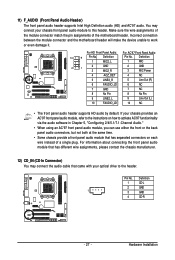
...; The front panel audio header supports HD audio by default. For HD Front Panel Audio: For AC'97 Front Panel Audio: 10 9 Pin No. Hardware Installation Make sure the wire assignments of the module connector match the pin assignments of a single plug.
...; The front panel audio header supports HD audio by default. For HD Front Panel Audio: For AC'97 Front Panel Audio: 10 9 Pin No. Hardware Installation Make sure the wire assignments of the module connector match the pin assignments of a single plug.
Manual
Page 28
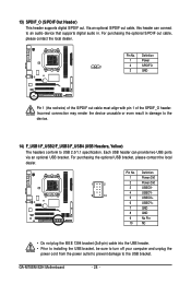
... header. • Prior to installing the USB bracket, be sure to turn off your computer and unplug the power cord from the power outlet to prevent damage to USB 2.0/1.1 specification. Via an optional S/PDIF out cable, this header can provide two USB ports via an optional USB bracket. GA-M78SM-S2H Motherboard - 28 - Definition...
... header. • Prior to installing the USB bracket, be sure to turn off your computer and unplug the power cord from the power outlet to prevent damage to USB 2.0/1.1 specification. Via an optional S/PDIF out cable, this header can provide two USB ports via an optional USB bracket. GA-M78SM-S2H Motherboard - 28 - Definition...

Manual
Page 29
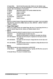
For purchasing the optional COM port cable, please contact the local dealer. 9 1 10 2 Pin No. 1 2 3 4 5 6 7 8 9 10 Definition NDCD NSIN NSOUT NDTR GND NDSR NRTS NCTS NRI No Pin 16) CI (Chassis Intrusion Header) This motherboard provides a chassis detection feature that detects if the chassis cover has been removed. 15) COM (Serial Port Header) The COM header can provide one serial port via an optional COM port cable. Definition 1 1 Signal 2 GND - 29 - Hardware Installation Pin No. This function requires a chassis with chassis intrusion detection design.
For purchasing the optional COM port cable, please contact the local dealer. 9 1 10 2 Pin No. 1 2 3 4 5 6 7 8 9 10 Definition NDCD NSIN NSOUT NDTR GND NDSR NRTS NCTS NRI No Pin 16) CI (Chassis Intrusion Header) This motherboard provides a chassis detection feature that detects if the chassis cover has been removed. 15) COM (Serial Port Header) The COM header can provide one serial port via an optional COM port cable. Definition 1 1 Signal 2 GND - 29 - Hardware Installation Pin No. This function requires a chassis with chassis intrusion detection design.
Manual
Page 36
... called conventional memory. Access Mode Sets the hard drive access mode. Precomp Write precompensation cylinder. Drive A Allows you to specify whether the installed floppy disk drive is 3-mode floppy disk drive, a Japanese standard floppy disk drive. All, But Keyboard The system boot will not stop.... (Default) All, But Diskette The system boot will stop for an error during the POST. Typically, 640 KB will not stop . GA-M78SM-S2H Motherboard - 36 - Capacity Approximate capacity of heads. Floppy 3 Mode Support Allows you to the information on the hard drive. Halt On ...
... called conventional memory. Access Mode Sets the hard drive access mode. Precomp Write precompensation cylinder. Drive A Allows you to specify whether the installed floppy disk drive is 3-mode floppy disk drive, a Japanese standard floppy disk drive. All, But Keyboard The system boot will not stop.... (Default) All, But Diskette The system boot will stop for an error during the POST. Typically, 640 KB will not stop . GA-M78SM-S2H Motherboard - 36 - Capacity Approximate capacity of heads. Floppy 3 Mode Support Allows you to the information on the hard drive. Halt On ...


