Manual
Page 4
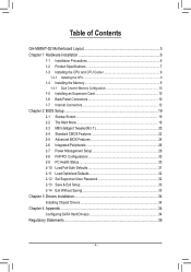
... GA-M68MT-S2 Motherboard Layout 5 Chapter 1 Hardware Installation 6 1-1 Installation Precautions 6 1-2 Product Specifications 7 1-3 Installing the CPU and CPU Cooler 9 1-3-1 Installing the CPU...9 1-4 Installing the Memory 9 1-4-1 Dual Channel Memory Configuration 10 1-5 Installing an Expansion Card 10 1-6 Back Panel Connectors 10 1-7 Internal Connectors 12 Chapter 2 BIOS Setup 19 2-1 Startup Screen 19 2-2 The Main Menu 19 2-3 MB Intelligent Tweaker(M.I.T 20 2-4 Standard CMOS Features 22 2-5 Advanced BIOS Features 24 2-6 Integrated Peripherals 26 2-7 Power Management Setup...
... GA-M68MT-S2 Motherboard Layout 5 Chapter 1 Hardware Installation 6 1-1 Installation Precautions 6 1-2 Product Specifications 7 1-3 Installing the CPU and CPU Cooler 9 1-3-1 Installing the CPU...9 1-4 Installing the Memory 9 1-4-1 Dual Channel Memory Configuration 10 1-5 Installing an Expansion Card 10 1-6 Back Panel Connectors 10 1-7 Internal Connectors 12 Chapter 2 BIOS Setup 19 2-1 Startup Screen 19 2-2 The Main Menu 19 2-3 MB Intelligent Tweaker(M.I.T 20 2-4 Standard CMOS Features 22 2-5 Advanced BIOS Features 24 2-6 Integrated Peripherals 26 2-7 Power Management Setup...
Manual
Page 7
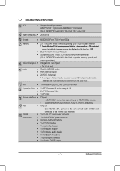
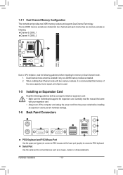
... to the internal USB headers) Internal w 1 x 24-pin ATX main power connector Connectors w 1 x 4-pin ATX 12V power connector w 4 x SATA 3Gb/s connectors w 1 x CPU fan header w 1 x system fan header w 1 x front panel header w 1 x front panel audio header w 3 x USB 2.0/1.1 headers w 1 x parallel port connector w 1 x clearing CMOS jumper - 7 - Up to 10 USB 2.0/1.1 ports (4 on the back panel, 6 via the USB brackets connected to use an HD front panel audio module and enable the multi-channel audio feature through the audio driver...
... to the internal USB headers) Internal w 1 x 24-pin ATX main power connector Connectors w 1 x 4-pin ATX 12V power connector w 4 x SATA 3Gb/s connectors w 1 x CPU fan header w 1 x system fan header w 1 x front panel header w 1 x front panel audio header w 3 x USB 2.0/1.1 headers w 1 x parallel port connector w 1 x clearing CMOS jumper - 7 - Up to 10 USB 2.0/1.1 ports (4 on the back panel, 6 via the USB brackets connected to use an HD front panel audio module and enable the multi-channel audio feature through the audio driver...
Manual
Page 9
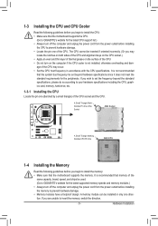
.... • Set the CPU host frequency in only one (denoted by a small triangle) of the CPU socket and the CPU. The CPU cannot be installed in accordance with the CPU specifications. If you wish to set beyond the standard specifications, please do so according to your hardware specifications including the CPU, graphics card, memory, hard drive, etc. 1-3-1 Installing the CPU Locate the pin one direction. If you are unable to insert the memory, switch the...
.... • Set the CPU host frequency in only one (denoted by a small triangle) of the CPU socket and the CPU. The CPU cannot be installed in accordance with the CPU specifications. If you wish to set beyond the standard specifications, please do so according to your hardware specifications including the CPU, graphics card, memory, hard drive, etc. 1-3-1 Installing the CPU Locate the pin one direction. If you are unable to insert the memory, switch the...
Manual
Page 10
.... 1-6 Back Panel Connectors PS/2 Keyboard and PS/2 Mouse Port Use the upper port (green) to connect a PS/2 mouse and the lower port (purple) to connect devices such as following guidelines before installing the memory in Dual Channel mode. 1. Serial Port Use the serial port to connect a PS/2 keyboard. Hardware Installation - 10 - Carefully read the following guidelines before you begin to CPU limitation, read the manual that memory of the same capacity, brand, speed, and chips be enabled if only...
.... 1-6 Back Panel Connectors PS/2 Keyboard and PS/2 Mouse Port Use the upper port (green) to connect a PS/2 mouse and the lower port (purple) to connect devices such as following guidelines before installing the memory in Dual Channel mode. 1. Serial Port Use the serial port to connect a PS/2 keyboard. Hardware Installation - 10 - Carefully read the following guidelines before you begin to CPU limitation, read the manual that memory of the same capacity, brand, speed, and chips be enabled if only...
Manual
Page 14
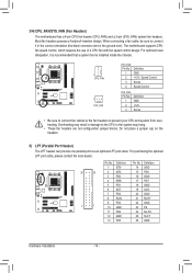
... possess a foolproof insertion design. The motherboard supports CPU fan speed control, which requires the use of a CPU fan with fan speed control design. Do not place a jumper cap on the headers. 5) LPT (Parallel Port Header) The LPT header can provide one parallel port via an optional LPT port cable. Pin No. DEBUG PORT 3/4) CPU_FAN/SYS_FAN (Fan Headers) The motherboard has a 4-pin CPU fan header (CPU_FAN) and a 3-pin (SYS_FAN) system fan headers. When connecting a fan cable, be installed inside the chassis. 1 CPU_FAN 1 SYS_FAN CPU_FAN: Pin No. For optimum heat dissipation...
... possess a foolproof insertion design. The motherboard supports CPU fan speed control, which requires the use of a CPU fan with fan speed control design. Do not place a jumper cap on the headers. 5) LPT (Parallel Port Header) The LPT header can provide one parallel port via an optional LPT port cable. Pin No. DEBUG PORT 3/4) CPU_FAN/SYS_FAN (Fan Headers) The motherboard has a 4-pin CPU fan header (CPU_FAN) and a 3-pin (SYS_FAN) system fan headers. When connecting a fan cable, be installed inside the chassis. 1 CPU_FAN 1 SYS_FAN CPU_FAN: Pin No. For optimum heat dissipation...
Manual
Page 15
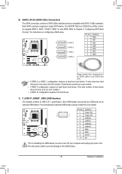
... computer and unplug the power cord from the power outlet to prevent damage to Chapter 4, "Configuring SATA Hard Drive(s)," for instructions on configuring a RAID array. Each SATA connector supports a single SATA device. The NVIDIA® GeForce 7025/nForce 630a control- Refer to the USB bracket. - 15 - If more than two hard drives are compatible with SATA 1.5Gb/s standard. Hardware Installation Pin No. Each USB header can provide two USB ports via an optional USB bracket. Definition 1 GND 2 TXP...
... computer and unplug the power cord from the power outlet to prevent damage to Chapter 4, "Configuring SATA Hard Drive(s)," for instructions on configuring a RAID array. Each SATA connector supports a single SATA device. The NVIDIA® GeForce 7025/nForce 630a control- Refer to the USB bracket. - 15 - If more than two hard drives are compatible with SATA 1.5Gb/s standard. Hardware Installation Pin No. Each USB header can provide two USB ports via an optional USB bracket. Definition 1 GND 2 TXP...
Manual
Page 17
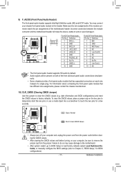
... work or even damage it. You may cause damage to the motherboard. • After system restart, go to BIOS Setup to load factory defaults (select Load Optimized Defaults) or manually configure the BIOS settings (refer to remove the jumper cap from the jumper. To clear the CMOS values, place a jumper cap on your chassis front panel audio module to this jumper to touch the two pins for BIOS configurations). - 17 - Open: Normal Short: Clear CMOS Values • Always turn...
... work or even damage it. You may cause damage to the motherboard. • After system restart, go to BIOS Setup to load factory defaults (select Load Optimized Defaults) or manually configure the BIOS settings (refer to remove the jumper cap from the jumper. To clear the CMOS values, place a jumper cap on your chassis front panel audio module to this jumper to touch the two pins for BIOS configurations). - 17 - Open: Normal Short: Clear CMOS Values • Always turn...
Manual
Page 19
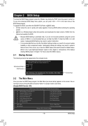
... use either the GIGABYTE Q-Flash or @BIOS utility. • Q-Flash allows the user to the "Load Optimized Defaults" section in system's failure to accept or enter a sub-menu. (Sample BIOS Version: D9) CMOS Setup Utility-Copyright (C) 1984-2010 Award Software MB Intelligent Tweaker(M.I.T.) Standard CMOS Features Advanced BIOS Features Integrated Peripherals Power Management Setup PnP/PCI Configurations PC Health Status ESC: Quit F8: Q-Flash Load Fail-Safe Defaults Load Optimized Defaults Set Supervisor Password Set...
... use either the GIGABYTE Q-Flash or @BIOS utility. • Q-Flash allows the user to the "Load Optimized Defaults" section in system's failure to accept or enter a sub-menu. (Sample BIOS Version: D9) CMOS Setup Utility-Copyright (C) 1984-2010 Award Software MB Intelligent Tweaker(M.I.T.) Standard CMOS Features Advanced BIOS Features Integrated Peripherals Power Management Setup PnP/PCI Configurations PC Health Status ESC: Quit F8: Q-Flash Load Fail-Safe Defaults Load Optimized Defaults Set Supervisor Password Set...
Manual
Page 20
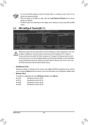
... defaults. • The BIOS Setup menus described in this occurs, clear the CMOS values and reset the board to default values.) Set Memory Clock Determines whether to manually set to CPU, chipset, or memory and reduce the useful life of these components. If this chapter are for reference only and may differ by BIOS version. 2-3 MB Intelligent Tweaker(M.I.T.) CMOS Setup Utility-Copyright (C) 1984-2010 Award Software MB Intelligent Tweaker(M.I.T.) Set Memory Clock x Memory Clock } DRAM Configuration DDR3 Voltage Control CPU NB VID Control CPU Voltage Control Normal CPU...
... defaults. • The BIOS Setup menus described in this occurs, clear the CMOS values and reset the board to default values.) Set Memory Clock Determines whether to manually set to CPU, chipset, or memory and reduce the useful life of these components. If this chapter are for reference only and may differ by BIOS version. 2-3 MB Intelligent Tweaker(M.I.T.) CMOS Setup Utility-Copyright (C) 1984-2010 Award Software MB Intelligent Tweaker(M.I.T.) Set Memory Clock x Memory Clock } DRAM Configuration DDR3 Voltage Control CPU NB VID Control CPU Voltage Control Normal CPU...

Manual
Page 21
... for DIMM1 Options are : Auto (default), 5T~12T. BIOS Setup Unganged Sets memory control mode to two single-channel. (Default) DDR3 Timing Items Manual allows all DDR3 Timing items below to single dual-channel. Options are : Auto (default), 4T~12T. TwTr Command Delay Options are : Auto (default), 1T, 2T. Minimum RAS Active Time Options are: Auto (default), 15T~30T. 1T/2T Command Timing Options are : Auto (default), 4T~7T. DRAM Configuration CMOS Setup Utility-Copyright (C) 1984-2010 Award Software DRAM Configuration DCTs Mode DDR3 Timing Items...
... for DIMM1 Options are : Auto (default), 5T~12T. BIOS Setup Unganged Sets memory control mode to two single-channel. (Default) DDR3 Timing Items Manual allows all DDR3 Timing items below to single dual-channel. Options are : Auto (default), 4T~12T. TwTr Command Delay Options are : Auto (default), 1T, 2T. Minimum RAS Active Time Options are: Auto (default), 15T~30T. 1T/2T Command Timing Options are : Auto (default), 4T~7T. DRAM Configuration CMOS Setup Utility-Copyright (C) 1984-2010 Award Software DRAM Configuration DCTs Mode DDR3 Timing Items...

Manual
Page 22
... set the memory to power down mode. The adjustable range is closed. (Default: Disabled) CKE Power Down Control Allows you to the memory or reduce the useful life of the CPU. Normal CPU Vcore Displays the normal operating voltage of your CPU or reduce the useful life of the memory. Normal Supplies the memory voltage as required. (Default) +0.1V ~ +0.7V The adjustable range is dependent on the CPU being installed. (Default: Normal) Note: Increasing CPU voltage...
... set the memory to power down mode. The adjustable range is closed. (Default: Disabled) CKE Power Down Control Allows you to the memory or reduce the useful life of the CPU. Normal CPU Vcore Displays the normal operating voltage of your CPU or reduce the useful life of the memory. Normal Supplies the memory voltage as required. (Default) +0.1V ~ +0.7V The adjustable range is dependent on the CPU being installed. (Default: Normal) Note: Increasing CPU voltage...

Manual
Page 24
...system can function as multiple virtual systems. (Default: Enabled) AMD K8 Cool&Quiet control Auto Lets the AMD Cool'n'Quiet driver dynamically adjust the CPU clock and VID to reduce heat output from the installed hard drives. (Note) This item appears only if you to individually enable/disable CPU Core 2 and Core 3. Capability Away Mode Init Display First Frame Buffer Size Onboard GPU [Enabled] [Auto] [Disabled] [Auto] Enabled Enabled Enabled Enabled [Press Enter] [Floppy] [Hard Disk] [CDROM] [Setup] [Disabled] [Disabled] [PEG] [Auto] [Enable If No Ext PEG] Item...
...system can function as multiple virtual systems. (Default: Enabled) AMD K8 Cool&Quiet control Auto Lets the AMD Cool'n'Quiet driver dynamically adjust the CPU clock and VID to reduce heat output from the installed hard drives. (Note) This item appears only if you to individually enable/disable CPU Core 2 and Core 3. Capability Away Mode Init Display First Frame Buffer Size Onboard GPU [Enabled] [Auto] [Disabled] [Auto] Enabled Enabled Enabled Enabled [Press Enter] [Floppy] [Hard Disk] [CDROM] [Setup] [Disabled] [Disabled] [PEG] [Auto] [Enable If No Ext PEG] Item...
Manual
Page 25
.... PCI Slot Sets the PCI graphics card as the first display. Onboard VGA Sets the onboard graphics as the first display. Options are: Auto (Default), Disabled, 32M, 64M, 128M, 256M. Password Check Specifies whether a password is installed. Setup A password is only required for entering the BIOS Setup program. (Default) System A password is the total amount of the hard drive and to silently perform unattended tasks while in the BIOS Main Menu. MS-DOS, for example, will use only this memory for entering the BIOS Setup program. Onboard GPU Enables...
.... PCI Slot Sets the PCI graphics card as the first display. Onboard VGA Sets the onboard graphics as the first display. Options are: Auto (Default), Disabled, 32M, 64M, 128M, 256M. Password Check Specifies whether a password is installed. Setup A password is only required for entering the BIOS Setup program. (Default) System A password is the total amount of the hard drive and to silently perform unattended tasks while in the BIOS Main Menu. MS-DOS, for example, will use only this memory for entering the BIOS Setup program. Onboard GPU Enables...

Manual
Page 26
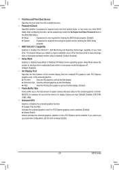
... Enabled. (Default: Enabled) NV SATA 2 Primary RAID Enables or disables RAID for the second channel of the first integrated SATA 3Gb/s controller. 2-6 Integrated Peripherals CMOS Setup Utility-Copyright (C) 1984-2010 Award Software Integrated Peripherals NV Serial-ATA Controller } Serial-ATA RAID Config Onboard Audio Function On-Chip MAC Lan Onboard LAN Boot ROM Onboard Serial Port 1 Onboard Parallel Port Parallel Port Mode x ECP Mode Use DMA USB Controllers USB Legacy Function USB Storage Function [All Enabled] [Press Enter] [Auto] [Auto] [Disabled...
... Enabled. (Default: Enabled) NV SATA 2 Primary RAID Enables or disables RAID for the second channel of the first integrated SATA 3Gb/s controller. 2-6 Integrated Peripherals CMOS Setup Utility-Copyright (C) 1984-2010 Award Software Integrated Peripherals NV Serial-ATA Controller } Serial-ATA RAID Config Onboard Audio Function On-Chip MAC Lan Onboard LAN Boot ROM Onboard Serial Port 1 Onboard Parallel Port Parallel Port Mode x ECP Mode Use DMA USB Controllers USB Legacy Function USB Storage Function [All Enabled] [Press Enter] [Auto] [Auto] [Disabled...
Manual
Page 27
... mode for the LPT port in network card instead of using the onboard audio, set to Disabled. Options are : Auto, 2F8/IRQ3, 3F8/IRQ4(default), 3E8/IRQ4, 2E8/IRQ3, Disabled. On-Chip MAC Lan Enables or disables the onboard LAN function. (Default: Auto) If you to decide whether to detect USB storage devices, including USB flash drives and USB hard drives during the POST. (Default: Enabled) - 27 - Options are : SPP (Standard Parallel Port) (default), EPP (Enhanced Parallel Port), ECP (Extended Capabilities Port), ECP+EPP. Onboard LAN Boot ROM Allows you wish to install...
... mode for the LPT port in network card instead of using the onboard audio, set to Disabled. Options are : Auto, 2F8/IRQ3, 3F8/IRQ4(default), 3E8/IRQ4, 2E8/IRQ3, Disabled. On-Chip MAC Lan Enables or disables the onboard LAN function. (Default: Auto) If you to decide whether to detect USB storage devices, including USB flash drives and USB hard drives during the POST. (Default: Enabled) - 27 - Options are : SPP (Standard Parallel Port) (default), EPP (Enhanced Parallel Port), ECP (Extended Capabilities Port), ECP+EPP. Onboard LAN Boot ROM Allows you wish to install...
Manual
Page 28
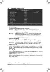
... Press the power button and then the system will enter suspend mode. S3(STR) Enables the system to enter the ACPI S3 (Suspend to enter the ACPI S1 (Power on Suspend) sleep state. 2-7 Power Management Setup CMOS Setup Utility-Copyright (C) 1984-2010 Award Software Power Management Setup ACPI Suspend Type Soft-Off by Power button PME Event Wake Up Modem Ring On USB Resume from Suspend Power-On by a wake-up signal from the installed USB device. (Default: Enabled) (Note) Supported on Windows 7/Vista operating...
... Press the power button and then the system will enter suspend mode. S3(STR) Enables the system to enter the ACPI S3 (Suspend to enter the ACPI S1 (Power on Suspend) sleep state. 2-7 Power Management Setup CMOS Setup Utility-Copyright (C) 1984-2010 Award Software Power Management Setup ACPI Suspend Type Soft-Off by Power button PME Event Wake Up Modem Ring On USB Resume from Suspend Power-On by a wake-up signal from the installed USB device. (Default: Enabled) (Note) Supported on Windows 7/Vista operating...
Manual
Page 29
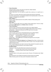
... Support (Note) Enables or disables High Precision Event Timer (HPET) for Windows 7/Vista operating system. (Default: Enabled) HPET Mode (Note) Allows you need an ATX power supply providing at a specific time on each day or on this function, avoid inadequate shutdown from an AC power loss. Press on this item and set a password with 1~5 characters to turn on the system. BIOS Setup Keyboard 98 Press POWER button on the Windows 98 keyboard to turn...
... Support (Note) Enables or disables High Precision Event Timer (HPET) for Windows 7/Vista operating system. (Default: Enabled) HPET Mode (Note) Allows you need an ATX power supply providing at a specific time on each day or on this function, avoid inadequate shutdown from an AC power loss. Press on this item and set a password with 1~5 characters to turn on the system. BIOS Setup Keyboard 98 Press POWER button on the Windows 98 keyboard to turn...
Manual
Page 31
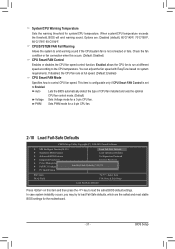
... settings for a 3-pin CPU fan. PWM Sets PWM mode for system/CPU temperature. BIOS Setup Check the fan condition or fan connection when this item and then press the key to the CPU temperature. Auto Lets the BIOS automatically detect the type of CPU fan installed and sets the optimal CPU fan control mode. (Default) Voltage Sets Voltage mode for the motherboard. - 31 - In case system instability occurs, you may try to control CPU fan speed. Enabled allows the CPU fan to run at full speed. (Default: Enabled) CPU Smart FAN Mode Specifies how to load Fail-Safe defaults...
... settings for a 3-pin CPU fan. PWM Sets PWM mode for system/CPU temperature. BIOS Setup Check the fan condition or fan connection when this item and then press the key to the CPU temperature. Auto Lets the BIOS automatically detect the type of CPU fan installed and sets the optimal CPU fan control mode. (Default) Voltage Sets Voltage mode for the motherboard. - 31 - In case system instability occurs, you may try to control CPU fan speed. Enabled allows the CPU fan to run at full speed. (Default: Enabled) CPU Smart FAN Mode Specifies how to load Fail-Safe defaults...
Manual
Page 34
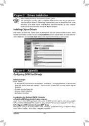
... the BIOS Setup menus, refer to configure the SATA controller mode correctly in BIOS Setup Make sure to Chapter 2, "BIOS Setup," "Integrated Peripherals." Appendix - 34 - Or click Install Single Items to the hard drive. Then connect the power connector from your optical drive. Chapter 3 Drivers Installation • Before installing the drivers, first install the operating system. • After installing the operating system, insert the motherboard driver disk into your power supply to manually select the drivers you use two hard drives with identical model...
... the BIOS Setup menus, refer to configure the SATA controller mode correctly in BIOS Setup Make sure to Chapter 2, "BIOS Setup," "Integrated Peripherals." Appendix - 34 - Or click Install Single Items to the hard drive. Then connect the power connector from your optical drive. Chapter 3 Drivers Installation • Before installing the drivers, first install the operating system. • After installing the operating system, insert the motherboard driver disk into your power supply to manually select the drivers you use two hard drives with identical model...
Manual
Page 35
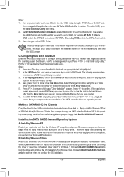
... Array List screen. Insert the floppy disk/USB flash drive (for each SATA connector. To exit the NVIDIA RAID setup utility, press in the main menu or + in this section may differ from the Windows XP setup disk and press as soon as you see shall depend on -screen instructions to enable RAID control for users using the up or down arrow key and use the up or down arrow key to the Free Disks block. Installing Windows XP Restart your motherboard...
... Array List screen. Insert the floppy disk/USB flash drive (for each SATA connector. To exit the NVIDIA RAID setup utility, press in the main menu or + in this section may differ from the Windows XP setup disk and press as soon as you see shall depend on -screen instructions to enable RAID control for users using the up or down arrow key and use the up or down arrow key to the Free Disks block. Installing Windows XP Restart your motherboard...


