Manual
Page 1
GA-M68M-S2P AM2+/AM2 socket motherboard for AMD Phenom™ II processor/ AMD Phenom™ processor/ AMD Athlon™ II processor/ AMD Athlon™ processor/ AMD Sempron™ processor User's Manual Rev. 1001 12ME-M68MS2P-1001R
GA-M68M-S2P AM2+/AM2 socket motherboard for AMD Phenom™ II processor/ AMD Phenom™ processor/ AMD Athlon™ II processor/ AMD Athlon™ processor/ AMD Sempron™ processor User's Manual Rev. 1001 12ME-M68MS2P-1001R
Manual
Page 2
Motherboard GA-M68M-S2P Nov. 9, 2009 Motherboard GA-M68M-S2P Nov. 9, 2009
Motherboard GA-M68M-S2P Nov. 9, 2009 Motherboard GA-M68M-S2P Nov. 9, 2009
Manual
Page 3
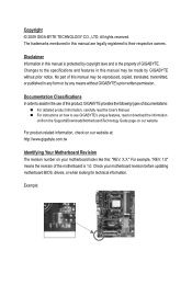
... detailed product information, carefully read the User's Manual. For instructions on how to use GIGABYTE's unique features, read or download the information on/from the Support&Downloads\Motherboard\Technology Guide page on your motherboard revision before updating motherboard BIOS, drivers, or when looking for technical information. Documentation Classifications In order to assist in...
... detailed product information, carefully read the User's Manual. For instructions on how to use GIGABYTE's unique features, read or download the information on/from the Support&Downloads\Motherboard\Technology Guide page on your motherboard revision before updating motherboard BIOS, drivers, or when looking for technical information. Documentation Classifications In order to assist in...
Manual
Page 4
Table of Contents Box Contents...6 Optional Items...6 GA-M68M-S2P Motherboard Layout 7 Block Diagram...8 Chapter 1 Hardware Installation 9 1-1 Installation Precautions 9 1-2 Product Specifications 10 1-3 Installing the CPU and CPU Cooler 13 1-3-1 Installing the CPU 13 1-3-2 Installing the CPU ...
Table of Contents Box Contents...6 Optional Items...6 GA-M68M-S2P Motherboard Layout 7 Block Diagram...8 Chapter 1 Hardware Installation 9 1-1 Installation Precautions 9 1-2 Product Specifications 10 1-3 Installing the CPU and CPU Cooler 13 1-3-1 Installing the CPU 13 1-3-2 Installing the CPU ...
Manual
Page 6
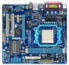
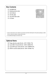
Optional Items Floppy disk drive cable (Part No. 12CF1-1FD001-7*R) 2-port USB 2.0 bracket (Part No. 12CR1-1UB030-5*R) 2-port SATA power cable (Part No. 12CF1-2SERPW-0*R) S/PDIF In and Out cable (Part No. 12CR1-1SPINO-1*R) - 6 - The box contents are for reference only. Box Contents GA-M68M-S2P Motherboard driver disk User's Manual One IDE cable One SATA 3Gb/s cable I/O Shield • The box contents above are subject to change without notice. • The motherboard image is for reference only and the actual items shall depend on the product package you obtain.
Optional Items Floppy disk drive cable (Part No. 12CF1-1FD001-7*R) 2-port USB 2.0 bracket (Part No. 12CR1-1UB030-5*R) 2-port SATA power cable (Part No. 12CF1-2SERPW-0*R) S/PDIF In and Out cable (Part No. 12CR1-1SPINO-1*R) - 6 - The box contents are for reference only. Box Contents GA-M68M-S2P Motherboard driver disk User's Manual One IDE cable One SATA 3Gb/s cable I/O Shield • The box contents above are subject to change without notice. • The motherboard image is for reference only and the actual items shall depend on the product package you obtain.
Manual
Page 9
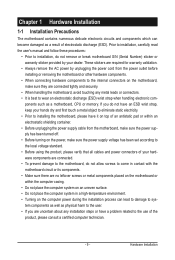
...• Turning on the computer power during the installation process can become damaged as a result of electrostatic discharge (ESD). ponents such as a motherboard, CPU or memory. Hardware Installation Prior to installation, carefully read the user's manual and follow these procedures: • Prior to installation, do...been turned off. • Before turning on the power, make sure they are connected tightly and securely. • When handling the motherboard, avoid touching any metal leads or connectors. • It is best to wear an electrostatic discharge (ESD) wrist strap when handling ...
...• Turning on the computer power during the installation process can become damaged as a result of electrostatic discharge (ESD). ponents such as a motherboard, CPU or memory. Hardware Installation Prior to installation, carefully read the user's manual and follow these procedures: • Prior to installation, do...been turned off. • Before turning on the power, make sure they are connected tightly and securely. • When handling the motherboard, avoid touching any metal leads or connectors. • It is best to wear an electrostatic discharge (ESD) wrist strap when handling ...

Manual
Page 12
... 3) Whether the CPU fan speed control function is supported will depend on the CPU cooler you install. (Note 4) Available functions in EasyTune may differ by motherboard model.
... 3) Whether the CPU fan speed control function is supported will depend on the CPU cooler you install. (Note 4) Available functions in EasyTune may differ by motherboard model.
Manual
Page 13
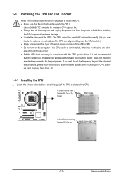
... socket.) • Apply an even and thin layer of thermal grease on the computer if the CPU cooler is not recommended that the motherboard supports the CPU. (Go to GIGABYTE's website for the latest CPU support list.) • Always turn on the surface of the CPU socket and the CPU. A Small Triangle...
... socket.) • Apply an even and thin layer of thermal grease on the computer if the CPU cooler is not recommended that the motherboard supports the CPU. (Go to GIGABYTE's website for the latest CPU support list.) • Always turn on the surface of the CPU socket and the CPU. A Small Triangle...
Manual
Page 14
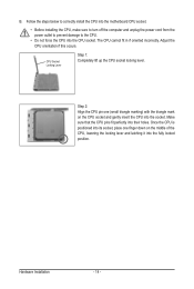
Follow the steps below to correctly install the CPU into the motherboard CPU socket. • Before installing the CPU, make sure to turn off the computer and unplug the power cord from the power outlet to prevent ...
Follow the steps below to correctly install the CPU into the motherboard CPU socket. • Before installing the CPU, make sure to turn off the computer and unplug the power cord from the power outlet to prevent ...
Manual
Page 15
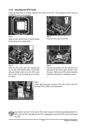
...cooler.) Step 5: Finally, attach the power connector of the CPU cooler to correctly install the CPU cooler on the CPU. (The following procedure uses the GIGABYTE cooler as the example.) Step 1: Apply an even and thin layer of thermal grease on the surface of the retention frame. 1-3-2 Installing the CPU ...Cooler Follow the steps below to the CPU fan header (CPU_FAN) on the motherboard. Step 3: Hook the CPU cooler clip to the mounting lug on the retention frame. On the other side,push straight down on the the CPU...
...cooler.) Step 5: Finally, attach the power connector of the CPU cooler to correctly install the CPU cooler on the CPU. (The following procedure uses the GIGABYTE cooler as the example.) Step 1: Apply an even and thin layer of thermal grease on the surface of the retention frame. 1-3-2 Installing the CPU ...Cooler Follow the steps below to the CPU fan header (CPU_FAN) on the motherboard. Step 3: Hook the CPU cooler clip to the mounting lug on the retention frame. On the other side,push straight down on the the CPU...
Manual
Page 16
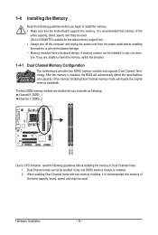
After the memory is installed. 2. Hardware Installation - 16 - Dual Channel mode cannot be used . (Go to GIGABYTE's website for the latest memory support list.) • Always turn off the computer and unplug the power cord from the power outlet ... that memory of the memory. A memory module can be used . When enabling Dual Channel mode with two memory modules, it is recommended that the motherboard supports the memory. 1-4 Installing the Memory Read the following guidelines before you are divided into two channels as following: Channel 0: DDR2_1 Channel 1: DDR2_2 ...
After the memory is installed. 2. Hardware Installation - 16 - Dual Channel mode cannot be used . (Go to GIGABYTE's website for the latest memory support list.) • Always turn off the computer and unplug the power cord from the power outlet ... that memory of the memory. A memory module can be used . When enabling Dual Channel mode with two memory modules, it is recommended that the motherboard supports the memory. 1-4 Installing the Memory Read the following guidelines before you are divided into two channels as following: Channel 0: DDR2_1 Channel 1: DDR2_2 ...

Manual
Page 17
Follow the steps below to the memory module. Place the memory module on this motherboard. As indicated in the picture on the left, place your memory modules in the memory sockets. Step 2: The clips at both ends of the socket ...
Follow the steps below to the memory module. Place the memory module on this motherboard. As indicated in the picture on the left, place your memory modules in the memory sockets. Step 2: The clips at both ends of the socket ...
Manual
Page 18
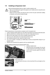
... turn off the computer and unplug the power cord from the power outlet before you begin to install an expansion card: • Make sure the motherboard supports the expansion card. Make sure the card is fully inserted into the slot. 4. Remove the metal slot cover from the slot. After installing all...
... turn off the computer and unplug the power cord from the power outlet before you begin to install an expansion card: • Make sure the motherboard supports the expansion card. Make sure the card is fully inserted into the slot. 4. Remove the metal slot cover from the slot. After installing all...
Manual
Page 20
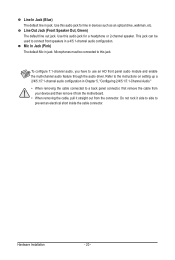
... be connected to connect front speakers in a 4/5.1-channel audio configuration. Microphones must be used to this jack. Do not rock it straight out from the motherboard. • When removing the cable, pull it side to side to use an HD front panel audio module and enable the multi-channel audio feature...
... be connected to connect front speakers in a 4/5.1-channel audio configuration. Microphones must be used to this jack. Do not rock it straight out from the motherboard. • When removing the cable, pull it side to side to use an HD front panel audio module and enable the multi-channel audio feature...

Manual
Page 21
..., make sure your devices are compliant with the connectors you wish to connect. • Before installing the devices, be sure to the connector on the motherboard. - 21 -
..., make sure your devices are compliant with the connectors you wish to connect. • Before installing the devices, be sure to the connector on the motherboard. - 21 -
Manual
Page 22
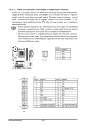
... power connector is not connected, the computer will not start. • To meet expansion requirements, it is turned off and all the components on the motherboard. Connect the power supply cable to the CPU. When using a 2x10 power supply. 21 43 ATX_12V ATX_12V: Pin No. 1 2 3 4 Definition GND ...supply cable into pins under the protective cover when using a 2x12 power supply, remove the protective cover from the main power connector on the motherboard. 1/2) ATX_12V/ATX (2x2 12V Power Connector and 2x12 Main Power Connector) With the use of the power connector, the power supply can...
... power connector is not connected, the computer will not start. • To meet expansion requirements, it is turned off and all the components on the motherboard. Connect the power supply cable to the CPU. When using a 2x10 power supply. 21 43 ATX_12V ATX_12V: Pin No. 1 2 3 4 Definition GND ...supply cable into pins under the protective cover when using a 2x12 power supply, remove the protective cover from the main power connector on the motherboard. 1/2) ATX_12V/ATX (2x2 12V Power Connector and 2x12 Main Power Connector) With the use of the power connector, the power supply can...
Manual
Page 23
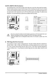
The motherboard supports CPU fan speed control, which requires the use of floppy disk drives supported are not configuration jumper blocks. Definition 1 GND 2 +12V / Speed Control 3 Sense 4 ... No. The pin 1 of the cable is typically designated by a stripe of the connector and the floppy disk drive cable. 3/4) CPU_FAN/SYS_FAN (Fan Headers) The motherboard has a 4-pin CPU fan header (CPU_FAN) and a 3-pin (SYS_FAN) system fan headers. Most fan headers possess a foolproof insertion design. When connecting a fan cable, be sure...
The motherboard supports CPU fan speed control, which requires the use of floppy disk drives supported are not configuration jumper blocks. Definition 1 GND 2 +12V / Speed Control 3 Sense 4 ... No. The pin 1 of the cable is typically designated by a stripe of the connector and the floppy disk drive cable. 3/4) CPU_FAN/SYS_FAN (Fan Headers) The motherboard has a 4-pin CPU fan header (CPU_FAN) and a 3-pin (SYS_FAN) system fan headers. Most fan headers possess a foolproof insertion design. When connecting a fan cable, be sure...

Manual
Page 26
...Pin No. Definition 1 CD-L 1 2 GND 3 GND 4 CD-R Hardware Installation - 26 - Incorrect connection between the module connector and the motherboard header will be present on each wire instead of a single plug. If your chassis provides an AC'97 front panel audio module, refer to ...Intel High Definition audio (HD) and AC'97 audio. You may connect the audio cable that has separated connectors on both of the motherboard header. For information about connecting the front panel audio module that has different wire assignments, please contact the chassis manufacturer. 10) CD_IN ...
...Pin No. Definition 1 CD-L 1 2 GND 3 GND 4 CD-R Hardware Installation - 26 - Incorrect connection between the module connector and the motherboard header will be present on each wire instead of a single plug. If your chassis provides an AC'97 front panel audio module, refer to ...Intel High Definition audio (HD) and AC'97 audio. You may connect the audio cable that has separated connectors on both of the motherboard header. For information about connecting the front panel audio module that has different wire assignments, please contact the chassis manufacturer. 10) CD_IN ...
Manual
Page 28
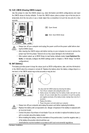
... off your computer and unplug the power cord. 2. 13) CLR_CMOS (Clearing CMOS Jumper) Use this jumper to factory defaults. You may cause damage to the motherboard. • After system restart, go to BIOS Setup to load factory defaults (select Load Optimized Defaults) or manually configure the BIOS settings (refer to replace...
... off your computer and unplug the power cord. 2. 13) CLR_CMOS (Clearing CMOS Jumper) Use this jumper to factory defaults. You may cause damage to the motherboard. • After system restart, go to BIOS Setup to load factory defaults (select Load Optimized Defaults) or manually configure the BIOS settings (refer to replace...
Manual
Page 29
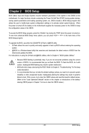
... may result in the CMOS on using the current version of BIOS from the Internet and updates the BIOS. For instructions on the motherboard. Its major functions include conducting the Power-On Self-Test (POST) during system startup, saving system parameters and loading operating system, ...etc. To upgrade the BIOS, use either the GIGABYTE Q-Flash or @BIOS utility. • Q-Flash allows the user to Chapter 4, "BIOS Update Utilities." • Because BIOS flashing is potentially risky...
... may result in the CMOS on using the current version of BIOS from the Internet and updates the BIOS. For instructions on the motherboard. Its major functions include conducting the Power-On Self-Test (POST) during system startup, saving system parameters and loading operating system, ...etc. To upgrade the BIOS, use either the GIGABYTE Q-Flash or @BIOS utility. • Q-Flash allows the user to Chapter 4, "BIOS Update Utilities." • Because BIOS flashing is potentially risky...


