Manual
Page 1
GA-M61PME-S2P AM2+/AM2 socket motherboard for AMD PhenomTM FX processor/AMD PhenomTM X4 processor/ AMD PhenomTM X3 processor/AMD AthlonTM X2 processor/ AMD AthlonTM processor/AMD SempronTM X2 processor/ AMD SempronTM processor User's Manual Rev. 1002 12ME-M61PMEP2-1002R
GA-M61PME-S2P AM2+/AM2 socket motherboard for AMD PhenomTM FX processor/AMD PhenomTM X4 processor/ AMD PhenomTM X3 processor/AMD AthlonTM X2 processor/ AMD AthlonTM processor/AMD SempronTM X2 processor/ AMD SempronTM processor User's Manual Rev. 1002 12ME-M61PMEP2-1002R
Manual
Page 2
Motherboard GA-M61PME-S2P Jan. 8, 2009 Motherboard GA-M61PME-S2P Jan. 8, 2009 -2-
Motherboard GA-M61PME-S2P Jan. 8, 2009 Motherboard GA-M61PME-S2P Jan. 8, 2009 -2-
Manual
Page 3
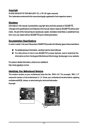
...by any means without prior notice. Copyright © 2008 GIGA-BYTE TECHNOLOGY CO., LTD. Check your motherboard looks like this product, GIGABYTE provides the following types of the motherboard is 1.0. Documentation Classifications In order to use of this : "REV: X.X." Changes to their respective... owners. Example: - 3 - For product-related information, check on our website at: http://www.gigabyte.com.tw Identifying Your Motherboard Revision The revision number on our website. The trademarks mentioned in this manual is the property of this manual are...
...by any means without prior notice. Copyright © 2008 GIGA-BYTE TECHNOLOGY CO., LTD. Check your motherboard looks like this product, GIGABYTE provides the following types of the motherboard is 1.0. Documentation Classifications In order to use of this : "REV: X.X." Changes to their respective... owners. Example: - 3 - For product-related information, check on our website at: http://www.gigabyte.com.tw Identifying Your Motherboard Revision The revision number on our website. The trademarks mentioned in this manual is the property of this manual are...
Manual
Page 4
Table of Contents Box Contents ...6 OptionalItems ...6 GA-M61PME-S2P Motherboard Layout 7 Block Diagram ...8 Chapter 1 Hardware Installation 9 1-1 Installation Precautions 9 1-2 Product Specifications 10 1-3 Installing the CPU and CPU Cooler 12 1-3-1 Installing the CPU 12 1-3-2 Installing the CPU ...
Table of Contents Box Contents ...6 OptionalItems ...6 GA-M61PME-S2P Motherboard Layout 7 Block Diagram ...8 Chapter 1 Hardware Installation 9 1-1 Installation Precautions 9 1-2 Product Specifications 10 1-3 Installing the CPU and CPU Cooler 12 1-3-1 Installing the CPU 12 1-3-2 Installing the CPU ...
Manual
Page 6
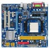
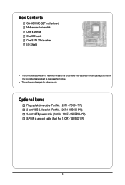
Optional Items Floppy disk drive cable (Part No. 12CF1-1FD001-7*R) 2-port USB 2.0 bracket (Part No. 12CR1-1UB030-5*R) 2-port SATA power cable (Part No. 12CF1-2SERPW-0*R) S/PDIF in and out cable (Part No. 12CR1-1SPINO-1*R) - 6 - The box contents are for reference only. Box Contents GA-M61PME-S2P motherboard Motherboard driver disk User's Manual One IDE cable One SATA 3Gb/s cables I/O Shield • The box contents above are subject to change without notice. • The motherboard image is for reference only and the actual items shall depend on product package you obtain.
Optional Items Floppy disk drive cable (Part No. 12CF1-1FD001-7*R) 2-port USB 2.0 bracket (Part No. 12CR1-1UB030-5*R) 2-port SATA power cable (Part No. 12CF1-2SERPW-0*R) S/PDIF in and out cable (Part No. 12CR1-1SPINO-1*R) - 6 - The box contents are for reference only. Box Contents GA-M61PME-S2P motherboard Motherboard driver disk User's Manual One IDE cable One SATA 3Gb/s cables I/O Shield • The box contents above are subject to change without notice. • The motherboard image is for reference only and the actual items shall depend on product package you obtain.
Manual
Page 9
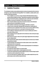
... are required for warranty validation. • Always remove the AC power by your hardware components are connected. • To prevent damage to the motherboard, do not have an ESD wrist strap, keep your hands dry and first touch a metal object to eliminate static electricity. • Prior to...to system components as well as physical harm to the user. • If you are connected tightly and securely. • When handling the motherboard, avoid touching any installation steps or have a problem related to the local voltage standard. • Before using the product, please verify that ...
... are required for warranty validation. • Always remove the AC power by your hardware components are connected. • To prevent damage to the motherboard, do not have an ESD wrist strap, keep your hands dry and first touch a metal object to eliminate static electricity. • Prior to...to system components as well as physical harm to the user. • If you are connected tightly and securely. • When handling the motherboard, avoid touching any installation steps or have a problem related to the local voltage standard. • Before using the product, please verify that ...
Manual
Page 10
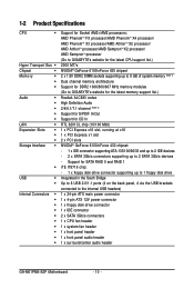
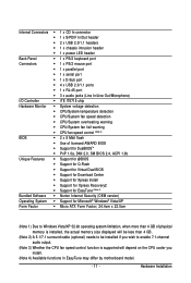
...up to 8 GB of system memory (Note 1) Dual channel memory architecture Support for DDR2 1066/800/667 MHz memory modules (Go to GIGABYTE's website for the latest memory support list.) Realtek ALC883 codec High Definition Audio 2/4/5.1/7.1-channel (Note 2) Support for S/PDIF In/Out Support... 2 x SATA 3Gb/s connectors 1 x CPU fan header 1 x system fan header 1 x front panel header 1 x front panel audio header 1 x surround/center audio header GA-M61PME-S2P Motherboard - 10 - Support for CD In RTL 8201CL chip (10/100 Mbit) 1 x PCI Express x16 slot, running at x16 1 x PCI Express x1 slot 2 x PCI ...
...up to 8 GB of system memory (Note 1) Dual channel memory architecture Support for DDR2 1066/800/667 MHz memory modules (Go to GIGABYTE's website for the latest memory support list.) Realtek ALC883 codec High Definition Audio 2/4/5.1/7.1-channel (Note 2) Support for S/PDIF In/Out Support... 2 x SATA 3Gb/s connectors 1 x CPU fan header 1 x system fan header 1 x front panel header 1 x front panel audio header 1 x surround/center audio header GA-M61PME-S2P Motherboard - 10 - Support for CD In RTL 8201CL chip (10/100 Mbit) 1 x PCI Express x16 slot, running at x16 1 x PCI Express x1 slot 2 x PCI ...
Manual
Page 11
... 3) Whether the CPU fan speed control function is supported will depend on the CPU cooler you install. (Note 4) Available functions in EasyTune may differ by motherboard model. - 11 -
... 3) Whether the CPU fan speed control function is supported will depend on the CPU cooler you install. (Note 4) Available functions in EasyTune may differ by motherboard model. - 11 -
Manual
Page 12
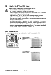
... It is not installed, otherwise overheating and damage of the Socket AM2 Socket A Small Triangle Marking Denotes CPU Pin One AM2+/AM2 CPU GA-M61PME-S2P Motherboard - 12 - 1-3 Installing the CPU and CPU Cooler Read the following guidelines before installing the CPU to prevent hardware damage. • Locate... card, memory, hard drive, etc. 1-3-1 Installing the CPU A. Locate the pin one of the CPU. mended that the motherboard supports the CPU. (Go to GIGABYTE's website for the peripherals. A Small Triangle Mark Denotes Pin One of the CPU may occur. • Set the CPU host...
... It is not installed, otherwise overheating and damage of the Socket AM2 Socket A Small Triangle Marking Denotes CPU Pin One AM2+/AM2 CPU GA-M61PME-S2P Motherboard - 12 - 1-3 Installing the CPU and CPU Cooler Read the following guidelines before installing the CPU to prevent hardware damage. • Locate... card, memory, hard drive, etc. 1-3-1 Installing the CPU A. Locate the pin one of the CPU. mended that the motherboard supports the CPU. (Go to GIGABYTE's website for the peripherals. A Small Triangle Mark Denotes Pin One of the CPU may occur. • Set the CPU host...
Manual
Page 13
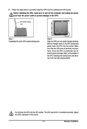
... socket, place one (small triangle marking) with the triangle mark on the middle of the CPU, lowering the locking lever and latching it into the motherboard CPU socket. Follow the steps below to the CPU. Adjust the CPU orientation if this occurs. - 13 - Before installing the CPU, make sure to turn...
... socket, place one (small triangle marking) with the triangle mark on the middle of the CPU, lowering the locking lever and latching it into the motherboard CPU socket. Follow the steps below to the CPU. Adjust the CPU orientation if this occurs. - 13 - Before installing the CPU, make sure to turn...
Manual
Page 14
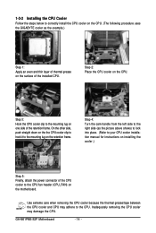
... down on the the CPU cooler clip to hook it to correctly install the CPU cooler on the CPU. (The following procedure uses the GIGABYTE cooler as the picture above shows) to lock into place. (Refer to your CPU cooler installation manual for instructions on installing the cooler.) ...Installing the CPU Cooler Follow the steps below to the mounting lug on the retention frame. Step 2: Place the CPU cooler on the CPU. GA-M61PME-S2P Motherboard - 14 - Use extreme care when removing the CPU cooler because the thermal grease/tape between the CPU cooler and CPU may damage the CPU.
... down on the the CPU cooler clip to hook it to correctly install the CPU cooler on the CPU. (The following procedure uses the GIGABYTE cooler as the picture above shows) to lock into place. (Refer to your CPU cooler installation manual for instructions on installing the cooler.) ...Installing the CPU Cooler Follow the steps below to the mounting lug on the retention frame. Step 2: Place the CPU cooler on the CPU. GA-M61PME-S2P Motherboard - 14 - Use extreme care when removing the CPU cooler because the thermal grease/tape between the CPU cooler and CPU may damage the CPU.
Manual
Page 15
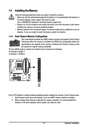
... same capacity, brand, speed, and chips be installed in Dual Channel mode. 1. Dual Channel mode cannot be used . (Go to GIGABYTE's website for the latest memory support list.) • Always turn off the computer and unplug the power cord from the power outlet before...DDR2 memory sockets and supports Dual Channel Technology. Hardware Installation When enabling Dual Channel mode with two memory modules, it is recommended that the motherboard supports the memory. A memory module can be used . - 15 - Enabling Dual Channel memory mode will automatically detect the specifications and...
... same capacity, brand, speed, and chips be installed in Dual Channel mode. 1. Dual Channel mode cannot be used . (Go to GIGABYTE's website for the latest memory support list.) • Always turn off the computer and unplug the power cord from the power outlet before...DDR2 memory sockets and supports Dual Channel Technology. Hardware Installation When enabling Dual Channel mode with two memory modules, it is recommended that the motherboard supports the memory. A memory module can be used . - 15 - Enabling Dual Channel memory mode will automatically detect the specifications and...
Manual
Page 16
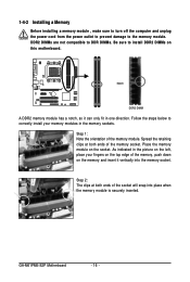
... indicated in the picture on the left, place your memory modules in one direction. Place the memory module on this motherboard. Spread the retaining clips at both ends of the memory module. GA-M61PME-S2P Motherboard - 16 - Step 1: Note the orientation of the memory socket. DDR2 DIMMs are not compatible to DDR DIMMs. Be sure...
... indicated in the picture on the left, place your memory modules in one direction. Place the memory module on this motherboard. Spread the retaining clips at both ends of the memory module. GA-M61PME-S2P Motherboard - 16 - Step 1: Note the orientation of the memory socket. DDR2 DIMMs are not compatible to DDR DIMMs. Be sure...
Manual
Page 17
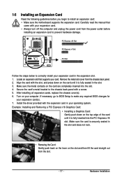
... the card until it is securely seated in the slot. 3. If necessary, go to BIOS Setup to install an expansion card: • Make sure the motherboard supports the expansion card. Align the card with the expansion card in the expansion slot. 1. 1-5 Installing an Expansion Card Read the following guidelines before installing...
... the card until it is securely seated in the slot. 3. If necessary, go to BIOS Setup to install an expansion card: • Make sure the motherboard supports the expansion card. Align the card with the expansion card in the expansion slot. 1. 1-5 Installing an Expansion Card Read the following guidelines before installing...
Manual
Page 18
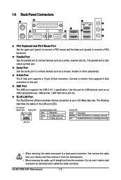
Do not rock it straight out from the motherboard. • When removing the cable, pull it side to side to prevent an electrical short inside the cable connector. The parallel port is occurring LAN ... 2.0/1.1 specification. RJ-45 LAN Port The Fast Ethernet LAN port provides Internet connection at up to connect devices such as a mouse, modem or other peripherals. GA-M61PME-S2P Motherboard - 18 - D-Sub Port The D-Sub port supports a 15-pin D-Sub connector. 1-6 Back Panel Connectors PS/2 Keyboard and PS/2 Mouse Port Use the upper port (green...
Do not rock it straight out from the motherboard. • When removing the cable, pull it side to side to prevent an electrical short inside the cable connector. The parallel port is occurring LAN ... 2.0/1.1 specification. RJ-45 LAN Port The Fast Ethernet LAN port provides Internet connection at up to connect devices such as a mouse, modem or other peripherals. GA-M61PME-S2P Motherboard - 18 - D-Sub Port The D-Sub port supports a 15-pin D-Sub connector. 1-6 Back Panel Connectors PS/2 Keyboard and PS/2 Mouse Port Use the upper port (green...
Manual
Page 20
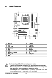
..., be sure to the connector on the computer, make sure the device cable has been securely attached to turn off the devices and your computer. GA-M61PME-S2P Motherboard - 20 - 1-7 Internal Connectors 1 3 16 11 12 17 9 13 14 1) ATX_12V 2) ATX 3) CPU_FAN 4) SYS_FAN 5) FDD 6) IDE 7) SATA2_0 / SATA2_1 8) PWR_LED 9) BAT 2 6 7 15 5 48 10 10) F_PANEL 11...
..., be sure to the connector on the computer, make sure the device cable has been securely attached to turn off the devices and your computer. GA-M61PME-S2P Motherboard - 20 - 1-7 Internal Connectors 1 3 16 11 12 17 9 13 14 1) ATX_12V 2) ATX 3) CPU_FAN 4) SYS_FAN 5) FDD 6) IDE 7) SATA2_0 / SATA2_1 8) PWR_LED 9) BAT 2 6 7 15 5 48 10 10) F_PANEL 11...
Manual
Page 21
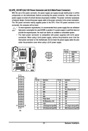
... power supply cable into pins under the protective cover when using a 2x12 power supply, remove the protective cover from the main power connector on the motherboard. If a power supply is compatible with power supplies with 2x10 power connectors. If the 12V power connector is not connected, the computer will not start...
... power supply cable into pins under the protective cover when using a 2x12 power supply, remove the protective cover from the main power connector on the motherboard. If a power supply is compatible with power supplies with 2x10 power connectors. If the 12V power connector is not connected, the computer will not start...
Manual
Page 22
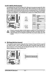
... a 4-pin CPU fan header (CPU_FAN) and a 3-pin system fan header (SYS_FAN). The motherboard supports CPU fan speed control, which requires the use of different color. 33 1 34 2 GA-M61PME-S2P Motherboard - 22 - Do not place a jumper cap on the headers. 5) FDD (Floppy Disk Drive Connector) This connector is the ground wire). The pin 1 of the...
... a 4-pin CPU fan header (CPU_FAN) and a 3-pin system fan header (SYS_FAN). The motherboard supports CPU fan speed control, which requires the use of different color. 33 1 34 2 GA-M61PME-S2P Motherboard - 22 - Do not place a jumper cap on the headers. 5) FDD (Floppy Disk Drive Connector) This connector is the ground wire). The pin 1 of the...
Manual
Page 24
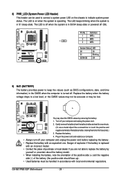
... when the computer is in accordance with an incorrect model. • Contact the place of explosion if the battery is replaced with local environmental regulations. GA-M61PME-S2P Motherboard - 24 -
... when the computer is in accordance with an incorrect model. • Contact the place of explosion if the battery is replaced with local environmental regulations. GA-M61PME-S2P Motherboard - 24 -
Manual
Page 26
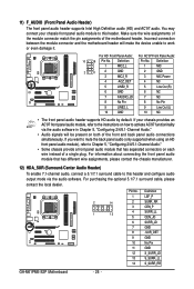
Incorrect connection between the module connector and the motherboard header will be present on both of the front and back panel audio connections simultaneously. If your chassis front panel audio module to this header .... 2 14 1 13 Pin No. 1 2 3 4 5 6 7 8 9 10 11 12 13 14 Definition LEF_P SURR_RR CEN_P SURR_LL CEN_JD SURR_JD GND -SUR_DET GND No Pin GND S_SURR_JD S_SURR_LL S_SURR_RR GA-M61PME-S2P Motherboard - 26 - Make sure the wire assignments of the module connector match the pin assignments of a single plug. You may connect your chassis provides an AC...
Incorrect connection between the module connector and the motherboard header will be present on both of the front and back panel audio connections simultaneously. If your chassis front panel audio module to this header .... 2 14 1 13 Pin No. 1 2 3 4 5 6 7 8 9 10 11 12 13 14 Definition LEF_P SURR_RR CEN_P SURR_LL CEN_JD SURR_JD GND -SUR_DET GND No Pin GND S_SURR_JD S_SURR_LL S_SURR_RR GA-M61PME-S2P Motherboard - 26 - Make sure the wire assignments of the module connector match the pin assignments of a single plug. You may connect your chassis provides an AC...


