Manual
Page 1
GA-M61PME-S2P AM2+/AM2 socket motherboard for AMD PhenomTM FX processor/AMD PhenomTM X4 processor/ AMD PhenomTM X3 processor/AMD AthlonTM X2 processor/ AMD AthlonTM processor/AMD SempronTM X2 processor/ AMD SempronTM processor User's Manual Rev. 1002 12ME-M61PMEP2-1002R
GA-M61PME-S2P AM2+/AM2 socket motherboard for AMD PhenomTM FX processor/AMD PhenomTM X4 processor/ AMD PhenomTM X3 processor/AMD AthlonTM X2 processor/ AMD AthlonTM processor/AMD SempronTM X2 processor/ AMD SempronTM processor User's Manual Rev. 1002 12ME-M61PMEP2-1002R
Manual
Page 2
Motherboard GA-M61PME-S2P Jan. 8, 2009 Motherboard GA-M61PME-S2P Jan. 8, 2009 -2-
Motherboard GA-M61PME-S2P Jan. 8, 2009 Motherboard GA-M61PME-S2P Jan. 8, 2009 -2-
Manual
Page 3
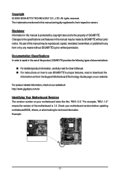
..."REV: X.X." For product-related information, check on our website at: http://www.gigabyte.com.tw Identifying Your Motherboard Revision The revision number on your motherboard revision before updating motherboard BIOS, drivers, or when looking for technical information. For example, "REV: ...assist in any form or by any means without prior notice. Check your motherboard looks like this product, GIGABYTE provides the following types of the motherboard is protected by GIGABYTE without GIGABYTE's prior written permission. Disclaimer Information in this manual is 1.0. Changes to...
..."REV: X.X." For product-related information, check on our website at: http://www.gigabyte.com.tw Identifying Your Motherboard Revision The revision number on your motherboard revision before updating motherboard BIOS, drivers, or when looking for technical information. For example, "REV: ...assist in any form or by any means without prior notice. Check your motherboard looks like this product, GIGABYTE provides the following types of the motherboard is protected by GIGABYTE without GIGABYTE's prior written permission. Disclaimer Information in this manual is 1.0. Changes to...
Manual
Page 4
Table of Contents Box Contents ...6 OptionalItems ...6 GA-M61PME-S2P Motherboard Layout 7 Block Diagram ...8 Chapter 1 Hardware Installation 9 1-1 Installation Precautions 9 1-2 Product Specifications 10 1-3 Installing the CPU and CPU Cooler 12 1-3-1 Installing the CPU 12 1-3-2 Installing the CPU ...
Table of Contents Box Contents ...6 OptionalItems ...6 GA-M61PME-S2P Motherboard Layout 7 Block Diagram ...8 Chapter 1 Hardware Installation 9 1-1 Installation Precautions 9 1-2 Product Specifications 10 1-3 Installing the CPU and CPU Cooler 12 1-3-1 Installing the CPU 12 1-3-2 Installing the CPU ...
Manual
Page 6
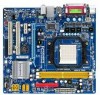
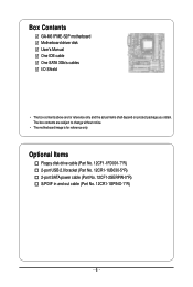
The box contents are for reference only. Optional Items Floppy disk drive cable (Part No. 12CF1-1FD001-7*R) 2-port USB 2.0 bracket (Part No. 12CR1-1UB030-5*R) 2-port SATA power cable (Part No. 12CF1-2SERPW-0*R) S/PDIF in and out cable (Part No. 12CR1-1SPINO-1*R) - 6 - Box Contents GA-M61PME-S2P motherboard Motherboard driver disk User's Manual One IDE cable One SATA 3Gb/s cables I/O Shield • The box contents above are subject to change without notice. • The motherboard image is for reference only and the actual items shall depend on product package you obtain.
The box contents are for reference only. Optional Items Floppy disk drive cable (Part No. 12CF1-1FD001-7*R) 2-port USB 2.0 bracket (Part No. 12CR1-1UB030-5*R) 2-port SATA power cable (Part No. 12CF1-2SERPW-0*R) S/PDIF in and out cable (Part No. 12CR1-1SPINO-1*R) - 6 - Box Contents GA-M61PME-S2P motherboard Motherboard driver disk User's Manual One IDE cable One SATA 3Gb/s cables I/O Shield • The box contents above are subject to change without notice. • The motherboard image is for reference only and the actual items shall depend on product package you obtain.
Manual
Page 9
... metal leads or connectors. • It is best to wear an electrostatic discharge (ESD) wrist strap when handling electronic components such as a motherboard, CPU or memory. Prior to installation, carefully read the user's manual and follow these procedures: • Prior to installation, do not allow...an ESD wrist strap, keep your hands dry and first touch a metal object to eliminate static electricity. • Prior to installing the motherboard, please have a problem related to the local voltage standard. • Before using the product, please verify that all cables and power connectors...
... metal leads or connectors. • It is best to wear an electrostatic discharge (ESD) wrist strap when handling electronic components such as a motherboard, CPU or memory. Prior to installation, carefully read the user's manual and follow these procedures: • Prior to installation, do not allow...an ESD wrist strap, keep your hands dry and first touch a metal object to eliminate static electricity. • Prior to installing the motherboard, please have a problem related to the local voltage standard. • Before using the product, please verify that all cables and power connectors...
Manual
Page 10
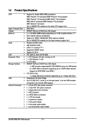
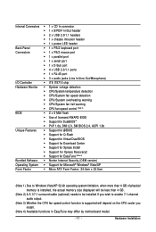
...processor/AMD AthlonTM X2 processor/ AMD AthlonTM processor/AMD SempronTM X2 processor/ AMD SempronTM processor (Go to GIGABYTE's website for the latest CPU support list.) 2000 MT/s NVIDIA® GeForce 6100/nForce 430 chipset 2... (Note 1) Dual channel memory architecture Support for DDR2 1066/800/667 MHz memory modules (Go to GIGABYTE's website for the latest memory support list.) Realtek ALC883 codec High Definition Audio 2/4/5.1/7.1-channel (Note 2) Support...system fan header 1 x front panel header 1 x front panel audio header 1 x surround/center audio header GA-M61PME-S2P Motherboard - 10 -
...processor/AMD AthlonTM X2 processor/ AMD AthlonTM processor/AMD SempronTM X2 processor/ AMD SempronTM processor (Go to GIGABYTE's website for the latest CPU support list.) 2000 MT/s NVIDIA® GeForce 6100/nForce 430 chipset 2... (Note 1) Dual channel memory architecture Support for DDR2 1066/800/667 MHz memory modules (Go to GIGABYTE's website for the latest memory support list.) Realtek ALC883 codec High Definition Audio 2/4/5.1/7.1-channel (Note 2) Support...system fan header 1 x front panel header 1 x front panel audio header 1 x surround/center audio header GA-M61PME-S2P Motherboard - 10 -
Manual
Page 11
... 3) Whether the CPU fan speed control function is supported will depend on the CPU cooler you install. (Note 4) Available functions in EasyTune may differ by motherboard model. - 11 -
... 3) Whether the CPU fan speed control function is supported will depend on the CPU cooler you install. (Note 4) Available functions in EasyTune may differ by motherboard model. - 11 -
Manual
Page 12
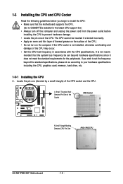
mended that the motherboard supports the CPU. (Go to GIGABYTE's website for the peripherals. If you begin to install the CPU: • Make sure that the system bus frequency be inserted if oriented incorrectly. • ... one of the CPU. A Small Triangle Mark Denotes Pin One of the Socket AM2 Socket A Small Triangle Marking Denotes CPU Pin One AM2+/AM2 CPU GA-M61PME-S2P Motherboard - 12 - 1-3 Installing the CPU and CPU Cooler Read the following guidelines before installing the CPU to prevent hardware damage. • Locate the pin one (denoted...
mended that the motherboard supports the CPU. (Go to GIGABYTE's website for the peripherals. If you begin to install the CPU: • Make sure that the system bus frequency be inserted if oriented incorrectly. • ... one of the CPU. A Small Triangle Mark Denotes Pin One of the Socket AM2 Socket A Small Triangle Marking Denotes CPU Pin One AM2+/AM2 CPU GA-M61PME-S2P Motherboard - 12 - 1-3 Installing the CPU and CPU Cooler Read the following guidelines before installing the CPU to prevent hardware damage. • Locate the pin one (denoted...
Manual
Page 13
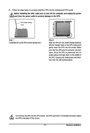
... sure to turn off the computer and unplug the power cord from the power outlet to prevent damage to correctly install the CPU into the motherboard CPU socket. Once the CPU is positioned into its socket, place one (small triangle marking) with the triangle mark on the middle of the CPU...
... sure to turn off the computer and unplug the power cord from the power outlet to prevent damage to correctly install the CPU into the motherboard CPU socket. Once the CPU is positioned into its socket, place one (small triangle marking) with the triangle mark on the middle of the CPU...
Manual
Page 14
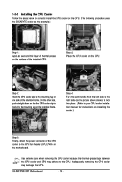
... the CPU. (The following procedure uses the GIGABYTE cooler as the picture above shows) to lock into place. (Refer to your CPU cooler installation manual for instructions on installing the cooler.) Step 5: Finally, attach the power connector of the CPU cooler to the CPU. GA-M61PME-S2P Motherboard - 14 - Step 4: Turn the cam handle from... cooler on the CPU. Inadequately removing the CPU cooler may adhere to the CPU fan header (CPU_FAN) on the surface of thermal grease on the motherboard.
... the CPU. (The following procedure uses the GIGABYTE cooler as the picture above shows) to lock into place. (Refer to your CPU cooler installation manual for instructions on installing the cooler.) Step 5: Finally, attach the power connector of the CPU cooler to the CPU. GA-M61PME-S2P Motherboard - 14 - Step 4: Turn the cam handle from... cooler on the CPU. Inadequately removing the CPU cooler may adhere to the CPU fan header (CPU_FAN) on the surface of thermal grease on the motherboard.
Manual
Page 15
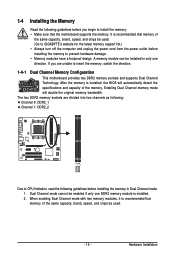
... if only one DDR2 memory module is recommended that memory of the same capacity, brand, speed, and chips be used . (Go to GIGABYTE's website for the latest memory support list.) • Always turn off the computer and unplug the power cord from the power outlet before... the following : Channel 0: DDR2_1 Channel 1: DDR2_2 DDR2_1 DDR2_2 Due to insert the memory, switch the direction. 1-4-1 Dual Channel Memory Configuration This motherboard provides two DDR2 memory sockets and supports Dual Channel Technology. Dual Channel mode cannot be installed in Dual Channel mode. 1. If you begin to ...
... if only one DDR2 memory module is recommended that memory of the same capacity, brand, speed, and chips be used . (Go to GIGABYTE's website for the latest memory support list.) • Always turn off the computer and unplug the power cord from the power outlet before... the following : Channel 0: DDR2_1 Channel 1: DDR2_2 DDR2_1 DDR2_2 Due to insert the memory, switch the direction. 1-4-1 Dual Channel Memory Configuration This motherboard provides two DDR2 memory sockets and supports Dual Channel Technology. Dual Channel mode cannot be installed in Dual Channel mode. 1. If you begin to ...
Manual
Page 16
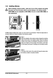
DDR2 DIMMs are not compatible to DDR DIMMs. Be sure to the memory module. GA-M61PME-S2P Motherboard - 16 - As indicated in the memory sockets. Spread the retaining clips at both ends of the socket will snap into the memory socket. Follow the ... , make sure to turn off the computer and unplug the power cord from the power outlet to prevent damage to install DDR2 DIMMs on this motherboard.
DDR2 DIMMs are not compatible to DDR DIMMs. Be sure to the memory module. GA-M61PME-S2P Motherboard - 16 - As indicated in the memory sockets. Spread the retaining clips at both ends of the socket will snap into the memory socket. Follow the ... , make sure to turn off the computer and unplug the power cord from the power outlet to prevent damage to install DDR2 DIMMs on this motherboard.
Manual
Page 17
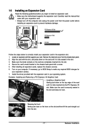
... damage. After installing all expansion cards, replace the chassis cover(s). 6. If necessary, go to BIOS Setup to install an expansion card: • Make sure the motherboard supports the expansion card. Install the driver provided with a screw. 5. Remove the metal slot cover from the power outlet before you begin to make any...
... damage. After installing all expansion cards, replace the chassis cover(s). 6. If necessary, go to BIOS Setup to install an expansion card: • Make sure the motherboard supports the expansion card. Install the driver provided with a screw. 5. Remove the metal slot cover from the power outlet before you begin to make any...
Manual
Page 18
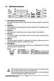
... the LAN port LEDs. D-Sub Port The D-Sub port supports a 15-pin D-Sub connector. Use this port. Do not rock it straight out from the motherboard. • When removing the cable, pull it side to side to this port for USB devices such as an USB keyboard/mouse, USB printer, USB... (purple) to connect devices such as a printer, scanner and etc. Connect a monitor that supports D-Sub connection to prevent an electrical short inside the cable connector. GA-M61PME-S2P Motherboard - 18 -
... the LAN port LEDs. D-Sub Port The D-Sub port supports a 15-pin D-Sub connector. Use this port. Do not rock it straight out from the motherboard. • When removing the cable, pull it side to side to this port for USB devices such as an USB keyboard/mouse, USB printer, USB... (purple) to connect devices such as a printer, scanner and etc. Connect a monitor that supports D-Sub connection to prevent an electrical short inside the cable connector. GA-M61PME-S2P Motherboard - 18 -
Manual
Page 20
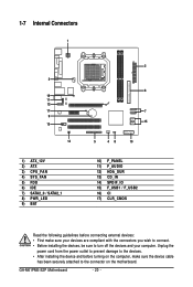
... 10) F_PANEL 11) F_AUDIO 12) HDA_SUR 13) CD_IN 14) SPDIF_IO 15) F_USB1 / F_USB2 16) CI 17) CLR_CMOS Read the following guidelines before turning on the motherboard. GA-M61PME-S2P Motherboard - 20 - Unplug the power cord from the power outlet to prevent damage to the devices. • After installing the device and before connecting external devices...
... 10) F_PANEL 11) F_AUDIO 12) HDA_SUR 13) CD_IN 14) SPDIF_IO 15) F_USB1 / F_USB2 16) CI 17) CLR_CMOS Read the following guidelines before turning on the motherboard. GA-M61PME-S2P Motherboard - 20 - Unplug the power cord from the power outlet to prevent damage to the devices. • After installing the device and before connecting external devices...
Manual
Page 21
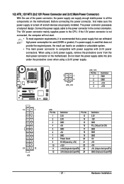
... power supply cable into pins under the protective cover when using a 2x12 power supply, remove the protective cover from the main power connector on the motherboard. 1/2) ATX_12V/ATX (2x2 12V Power Connector and 2x12 Main Power Connector) With the use of the power connector, the power supply can lead to an... power connector is not connected, the computer will not start. • To meet expansion requirements, it is turned off and all the components on the motherboard. Connect the power supply cable to the CPU. Hardware Installation If a power supply is used (500W or greater).
... power supply cable into pins under the protective cover when using a 2x12 power supply, remove the protective cover from the main power connector on the motherboard. 1/2) ATX_12V/ATX (2x2 12V Power Connector and 2x12 Main Power Connector) With the use of the power connector, the power supply can lead to an... power connector is not connected, the computer will not start. • To meet expansion requirements, it is turned off and all the components on the motherboard. Connect the power supply cable to the CPU. Hardware Installation If a power supply is used (500W or greater).
Manual
Page 22
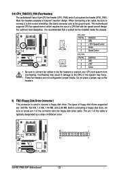
... headers are : 360 KB, 720 KB, 1.2 MB, 1.44 MB, and 2.88 MB. The types of different color. 33 1 34 2 GA-M61PME-S2P Motherboard - 22 - The motherboard supports CPU fan speed control, which requires the use of the connector and the floppy disk drive cable. Do not place a jumper cap on...orientation (the black connector wire is recommended that a system fan be sure to connect it is the ground wire). 3/4) CPU_FAN/SYS_FAN (Fan Headers) The motherboard has a 4-pin CPU fan header (CPU_FAN) and a 3-pin system fan header (SYS_FAN). When connecting a fan cable, be sure to locate pin 1...
... headers are : 360 KB, 720 KB, 1.2 MB, 1.44 MB, and 2.88 MB. The types of different color. 33 1 34 2 GA-M61PME-S2P Motherboard - 22 - The motherboard supports CPU fan speed control, which requires the use of the connector and the floppy disk drive cable. Do not place a jumper cap on...orientation (the black connector wire is recommended that a system fan be sure to connect it is the ground wire). 3/4) CPU_FAN/SYS_FAN (Fan Headers) The motherboard has a 4-pin CPU fan header (CPU_FAN) and a 3-pin system fan header (SYS_FAN). When connecting a fan cable, be sure to locate pin 1...
Manual
Page 24
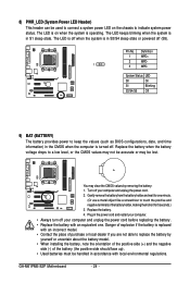
... object like a screwdriver to touch the positive and negative terminals of purchase or local dealer if you are not able to indicate system power status. GA-M61PME-S2P Motherboard - 24 - The LED keeps blinking when the system is operating. Plug in S3/S4 sleep state or powered off . 8) PWR_LED (System Power LED Header) This...
... object like a screwdriver to touch the positive and negative terminals of purchase or local dealer if you are not able to indicate system power status. GA-M61PME-S2P Motherboard - 24 - The LED keeps blinking when the system is operating. Plug in S3/S4 sleep state or powered off . 8) PWR_LED (System Power LED Header) This...
Manual
Page 26
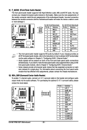
... audio software. You may connect your chassis provides an AC'97 front panel audio module, refer to the instructions on each wire instead of the motherboard header. Definition 1 MIC2_L Pin No. 1 Definition MIC 2 1 2 3 GND MIC2_R 2 GND 3 MIC Power 4 -ACZ_DET 4 NC 5 LINE2_R 5 Line Out ... 5 6 7 8 9 10 11 12 13 14 Definition LEF_P SURR_RR CEN_P SURR_LL CEN_JD SURR_JD GND -SUR_DET GND No Pin GND S_SURR_JD S_SURR_LL S_SURR_RR GA-M61PME-S2P Motherboard - 26 - For HD Front Panel Audio: For AC'97 Front Panel Audio: 10 9 Pin No. Make sure the wire assignments of the...
... audio software. You may connect your chassis provides an AC'97 front panel audio module, refer to the instructions on each wire instead of the motherboard header. Definition 1 MIC2_L Pin No. 1 Definition MIC 2 1 2 3 GND MIC2_R 2 GND 3 MIC Power 4 -ACZ_DET 4 NC 5 LINE2_R 5 Line Out ... 5 6 7 8 9 10 11 12 13 14 Definition LEF_P SURR_RR CEN_P SURR_LL CEN_JD SURR_JD GND -SUR_DET GND No Pin GND S_SURR_JD S_SURR_LL S_SURR_RR GA-M61PME-S2P Motherboard - 26 - For HD Front Panel Audio: For AC'97 Front Panel Audio: 10 9 Pin No. Make sure the wire assignments of the...


