
Manual
Page 1
GA-M59SLI-S5 / GA-M59SLI-S4 AMD Socket AM2 Processor Motherboard User's Manual Rev. 1003 12ME-M59SLIS5-1003R * The WEEE marking on the product indicates this product must not be disposed of with user's other household waste and must be handed over to a designated collection point for the recycling of waste electrical and electronic equipment!! * The WEEE marking applies only in European Union's member states.
GA-M59SLI-S5 / GA-M59SLI-S4 AMD Socket AM2 Processor Motherboard User's Manual Rev. 1003 12ME-M59SLIS5-1003R * The WEEE marking on the product indicates this product must not be disposed of with user's other household waste and must be handed over to a designated collection point for the recycling of waste electrical and electronic equipment!! * The WEEE marking applies only in European Union's member states.

Manual
Page 4
Table of Contents ItemChecklist ...6 OptionalAccessories ...6 GA-M59SLI-S5 Motherboard Layout 7 GA-M59SLI-S4 Motherboard Layout 8 Block Diagram ...9 Chapter 1 Hardware Installation 11 1-1 Considerations Prior to Installation 11 1-2 Feature Summary 12 1-3 Installation of the CPU and CPU Cooler 15 1-3-1 Installation of ...
Table of Contents ItemChecklist ...6 OptionalAccessories ...6 GA-M59SLI-S5 Motherboard Layout 7 GA-M59SLI-S4 Motherboard Layout 8 Block Diagram ...9 Chapter 1 Hardware Installation 11 1-1 Considerations Prior to Installation 11 1-2 Feature Summary 12 1-3 Installation of the CPU and CPU Cooler 15 1-3-1 Installation of ...

Manual
Page 7
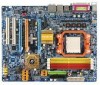
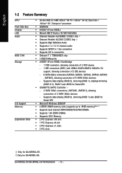
GA-M59SLI-S5 Motherboard Layout KB_MS OPTICAL ATX_12V_2X Socket AM2 R_1394 ATX COMA LPT USB LAN1 USB LAN2 F_AUDIO DDRII1 DDRII2 DDRII3 DDRII4 PWR_FAN CPU_FAN Marvell 88E1116 AUDIO PCIE_1 Marvell 88E1116 nVIDIA® nForce 590SLI Northbridge GA-M59SLI-S5 PCIE_16_1 IDE1 FDD SATAII5 ...SATAII4 SYS_FAN CODEC PCIE_2 PCIE_8 CD_IN SPDIF_I PCIE_16_2 IT8716 PCI1 PCI2 CI TPM F1_1394 nVIDIA® nForce 590SLI Southbridge SATAII1 SATAII3 TSB43AB23 SATAII0 SATAII2 GIGABYTE SATA2 BAT Backup BIOS CLR_CMOS...
GA-M59SLI-S5 Motherboard Layout KB_MS OPTICAL ATX_12V_2X Socket AM2 R_1394 ATX COMA LPT USB LAN1 USB LAN2 F_AUDIO DDRII1 DDRII2 DDRII3 DDRII4 PWR_FAN CPU_FAN Marvell 88E1116 AUDIO PCIE_1 Marvell 88E1116 nVIDIA® nForce 590SLI Northbridge GA-M59SLI-S5 PCIE_16_1 IDE1 FDD SATAII5 ...SATAII4 SYS_FAN CODEC PCIE_2 PCIE_8 CD_IN SPDIF_I PCIE_16_2 IT8716 PCI1 PCI2 CI TPM F1_1394 nVIDIA® nForce 590SLI Southbridge SATAII1 SATAII3 TSB43AB23 SATAII0 SATAII2 GIGABYTE SATA2 BAT Backup BIOS CLR_CMOS...

Manual
Page 8
GA-M59SLI-S4 Motherboard Layout KB_MS OPTICAL ATX_12V Socket AM2 R_1394 ATX COMA LPT USB USB IDE1 CPU_FAN DDRII1 DDRII2 DDRII3 DDRII4 PWR_FAN LAN2 F_AUDIO AUDIO PCIE_1 Marvell 88E1116 nVIDIA® nForce 590SLI Northbridge GA-M59SLI-S4 PCIE_16_1 FDD SATAII5 SATAII4 SYS_FAN CODEC PCIE_2 PCIE_8 nVIDIA® nForce 590SLI Southbridge SATAII1 SATAII3 CD_IN SPDIF_I IT8716 PCIE_16_2 SATAII0 SB_FAN SATAII2 PCI1 PCI2 CI TSB43AB23 F1_1394 F2_1394 BAT CLR_CMOS BIOS F_PANEL F_USB3 F_USB2 F_USB1 PCIE_12V PWR_LED - 8 -
GA-M59SLI-S4 Motherboard Layout KB_MS OPTICAL ATX_12V Socket AM2 R_1394 ATX COMA LPT USB USB IDE1 CPU_FAN DDRII1 DDRII2 DDRII3 DDRII4 PWR_FAN LAN2 F_AUDIO AUDIO PCIE_1 Marvell 88E1116 nVIDIA® nForce 590SLI Northbridge GA-M59SLI-S4 PCIE_16_1 FDD SATAII5 SATAII4 SYS_FAN CODEC PCIE_2 PCIE_8 nVIDIA® nForce 590SLI Southbridge SATAII1 SATAII3 CD_IN SPDIF_I IT8716 PCIE_16_2 SATAII0 SB_FAN SATAII2 PCI1 PCI2 CI TSB43AB23 F1_1394 F2_1394 BAT CLR_CMOS BIOS F_PANEL F_USB3 F_USB2 F_USB1 PCIE_12V PWR_LED - 8 -
Manual
Page 11
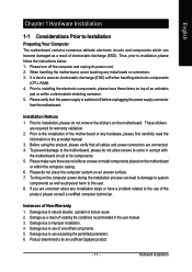
...2. Damage due to use of an antistatic pad or within the computer casing. 6. Thus, prior to be an unofficial Gigabyte product. - 11 - Turning on the motherboard. Damage as a result of uncertified components. 5. Hardware Installation Please do not allow screws to come in the user manual....ESD) cuff when handling electronic components (CPU, RAM). 4. Damage due to use of violating the conditions recommended in contact with the motherboard circuit or its power cord. 2. If you are connected. 4. Prior to installing the electronic components, please have a problem related to...
...2. Damage due to use of an antistatic pad or within the computer casing. 6. Thus, prior to be an unofficial Gigabyte product. - 11 - Turning on the motherboard. Damage as a result of uncertified components. 5. Hardware Installation Please do not allow screws to come in the user manual....ESD) cuff when handling electronic components (CPU, RAM). 4. Damage due to use of violating the conditions recommended in contact with the motherboard circuit or its power cord. 2. If you are connected. 4. Prior to installing the electronic components, please have a problem related to...
Manual
Page 12
...Supports 2 / 4 / 6 / 8 channel audio Š Supports SPDIF In / Out connection Š Supports CD In connection Š Onboard T.I. GA-M59SLI-S5/GA-M59SLI-S4 Motherboard - 12 - Supports data striping (RAID 0), mirroring (RAID 1) and JBOD for Serial ATA Š Microsoft Windows 2000/XP Š 4 DDRII DIMM...Express x16 slot Š 1 PCI Express x8 slot Š 2 PCI Express x1 slots Š 2 PCI slots Only for Serial ATA Š GIGABYTE SATA2 Controller - 2 SATA 3Gb/s connectors (JSATAII0, JSATAII1), allowing connection of 6 SATA 3Gb/s devices - TSB43AB23 chip Š 3 IEEE1394a ports &#...
...Supports 2 / 4 / 6 / 8 channel audio Š Supports SPDIF In / Out connection Š Supports CD In connection Š Onboard T.I. GA-M59SLI-S5/GA-M59SLI-S4 Motherboard - 12 - Supports data striping (RAID 0), mirroring (RAID 1) and JBOD for Serial ATA Š Microsoft Windows 2000/XP Š 4 DDRII DIMM...Express x16 slot Š 1 PCI Express x8 slot Š 2 PCI Express x1 slots Š 2 PCI slots Only for Serial ATA Š GIGABYTE SATA2 Controller - 2 SATA 3Gb/s connectors (JSATAII0, JSATAII1), allowing connection of 6 SATA 3Gb/s devices - TSB43AB23 chip Š 3 IEEE1394a ports &#...
Manual
Page 14
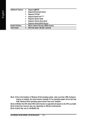
GA-M59SLI-S5/GA-M59SLI-S4 Motherboard - 14 - English Additional Features Š Supports @BIOS Š Supports Download Center Š Supports Q-Flash Š Supports EasyTune(Note 3) Š Supports Xpress Install Š Supports Xpress ... is installed, the actual memory available for the operating system will depend on the CPU you install. (Note 3) EasyTune functions may vary depending on different motherboards. (Note 4) Silent Pipe only for GA-M59SLI-S5.
GA-M59SLI-S5/GA-M59SLI-S4 Motherboard - 14 - English Additional Features Š Supports @BIOS Š Supports Download Center Š Supports Q-Flash Š Supports EasyTune(Note 3) Š Supports Xpress Install Š Supports Xpress ... is installed, the actual memory available for the operating system will depend on the CPU you install. (Note 3) EasyTune functions may vary depending on different motherboards. (Note 4) Silent Pipe only for GA-M59SLI-S5.
Manual
Page 15
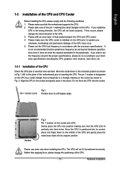
... use , otherwise overheating and permanent damage of the CPU may occur. 5. Please set the CPU host frequency in Fig. 1 (90o to the plane of the motherboard) prior to the unlocked position as shown in the wrong direction, the CPU will not fit if positioned incorrectly. If you wish to the socket... of the pin 1 marking (the small triangle) on the socket and CPU. Hardware Installation It is designated on the CPU by a small triangle that the motherboard supports the CPU. 2.
... use , otherwise overheating and permanent damage of the CPU may occur. 5. Please set the CPU host frequency in Fig. 1 (90o to the plane of the motherboard) prior to the unlocked position as shown in the wrong direction, the CPU will not fit if positioned incorrectly. If you wish to the socket... of the pin 1 marking (the small triangle) on the socket and CPU. Hardware Installation It is designated on the CPU by a small triangle that the motherboard supports the CPU. 2.

Manual
Page 16
... Installation of the CPU Cooler Fig.1 Before installing the CPU cooler, please first add an even layer of heat paste on the motherboard so that either thermal tape rather than heat paste be used for detailed installation instructions). To prevent such an occurrence, it is ...prevent CPU overheating. Install all the CPU cooler components (Please refer to the CPU_FAN connector located on the surface of the heat paste. GA-M59SLI-S5/GA-M59SLI-S4 Motherboard - 16 - Fig.2 Please connect the CPU cooler power connector to the cooler manual for heat dissipation or using extreme care when ...
... Installation of the CPU Cooler Fig.1 Before installing the CPU cooler, please first add an even layer of heat paste on the motherboard so that either thermal tape rather than heat paste be used for detailed installation instructions). To prevent such an occurrence, it is ...prevent CPU overheating. Install all the CPU cooler components (Please refer to the CPU_FAN connector located on the surface of the heat paste. GA-M59SLI-S5/GA-M59SLI-S4 Motherboard - 16 - Fig.2 Please connect the CPU cooler power connector to the cooler manual for heat dissipation or using extreme care when ...

Manual
Page 17
... comply with each slot. Hardware Installation Before installing or removing memory modules, please make sure that the memory used is supported by the motherboard. If you wish to remove the DIMM module. - 17 - The memory capacity used . 2. Insert the DIMM memory module vertically ...following conditions: 1. Please make sure that the computer power is recommended that they can be inserted only in one direction. The motherboard supports DDRII memory modules, whereby BIOS will automatically detect memory capacity and specifications. A memory module can be used can only fit...
... comply with each slot. Hardware Installation Before installing or removing memory modules, please make sure that the memory used is supported by the motherboard. If you wish to remove the DIMM module. - 17 - The memory capacity used . 2. Insert the DIMM memory module vertically ...following conditions: 1. Please make sure that the computer power is recommended that they can be inserted only in one direction. The motherboard supports DDRII memory modules, whereby BIOS will automatically detect memory capacity and specifications. A memory module can be used can only fit...

Manual
Page 18
...configuration table: (DS: Double Side, SS: Single Side, "--": Empty) DIMM Socket 2 memory modules 4 memory modules DDRII1 DS/SS - GA-M59SLI-S5/GA-M59SLI-S4 Motherboard - 18 - Due to CPU limitation, if you wish to achieve Dual Channel mode, we recommend installing them into DIMM sockets of identical brand...chips, and speed. Dual Channel mode will double. DS/SS DDRII2 DS/SS - English Dual Channel Memory Configuration The GA-M59SLI-S5/GA-M59SLI-S4 supports the Dual Channel Technology. To enable Dual Channel mode with four memory modules, it is recommended to use memory ...
...configuration table: (DS: Double Side, SS: Single Side, "--": Empty) DIMM Socket 2 memory modules 4 memory modules DDRII1 DS/SS - GA-M59SLI-S5/GA-M59SLI-S4 Motherboard - 18 - Due to CPU limitation, if you wish to achieve Dual Channel mode, we recommend installing them into DIMM sockets of identical brand...chips, and speed. Dual Channel mode will double. DS/SS DDRII2 DS/SS - English Dual Channel Memory Configuration The GA-M59SLI-S5/GA-M59SLI-S4 supports the Dual Channel Technology. To enable Dual Channel mode with four memory modules, it is recommended to use memory ...
Manual
Page 19
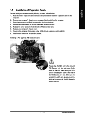
... steps outlined below: 1. Press the expansion card firmly into the computer. 2. Install related driver from the computer. 3. Power on the card are indeed seated in motherboard. 4. Read the related expansion card's instruction document before install the expansion card into expansion slot in the slot. 5.
... steps outlined below: 1. Press the expansion card firmly into the computer. 2. Install related driver from the computer. 3. Power on the card are indeed seated in motherboard. 4. Read the related expansion card's instruction document before install the expansion card into expansion slot in the slot. 5.

Manual
Page 20
...! Together, the NVIDIA SLI technologies work seamlessly to allow two graphics cards to configure an SLI system on the GAM59SLI-S5/GA-M59SLI-S4 motherboard. If you begin-The exact power requirements will depend on the PCIE_16_1 slot to your overall system configurations. This section introduces...card system, we recommend installing the graphics card on your system and the two SLI graphics cards. For example: GIGABYTE GV-NX76T256D-RH). GA-M59SLI-S5/GA-M59SLI-S4 Motherboard - 20 - You need a power supply that can provide sufficient and stable power to ensure better display performance.
...! Together, the NVIDIA SLI technologies work seamlessly to allow two graphics cards to configure an SLI system on the GAM59SLI-S5/GA-M59SLI-S4 motherboard. If you begin-The exact power requirements will depend on the PCIE_16_1 slot to your overall system configurations. This section introduces...card system, we recommend installing the graphics card on your system and the two SLI graphics cards. For example: GIGABYTE GV-NX76T256D-RH). GA-M59SLI-S5/GA-M59SLI-S4 Motherboard - 20 - You need a power supply that can provide sufficient and stable power to ensure better display performance.

Manual
Page 21
... of graphics card Step 3: In order to securely fix the bridge connector beween the two cards, you must install the retention bracket included with the motherboard and secure the retention bracket to the PCIE_16_1 and PCIE_16_2 slots. Make sure the two mini female slots on the top of the bridge connector...
... of graphics card Step 3: In order to securely fix the bridge connector beween the two cards, you must install the retention bracket included with the motherboard and secure the retention bracket to the PCIE_16_1 and PCIE_16_2 slots. Make sure the two mini female slots on the top of the bridge connector...
Manual
Page 22
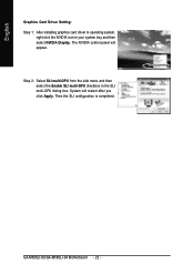
Then the SLI configuration is completed. GA-M59SLI-S5/GA-M59SLI-S4 Motherboard - 22 - System will appear. English Graphics Card Driver Setting: Step 1: After installing graphics card driver in operating system, right-click the NVIDIA icon in the SLI multi-GPU dialog box. The NVIDIA control panel will restart after you click Apply. Step 2: Select SLI multi-GPU from the side menu and then select the Enable SLI multi-GPU checkbox in your system tray and then select NVIDIA Display.
Then the SLI configuration is completed. GA-M59SLI-S5/GA-M59SLI-S4 Motherboard - 22 - System will appear. English Graphics Card Driver Setting: Step 1: After installing graphics card driver in operating system, right-click the NVIDIA icon in the SLI multi-GPU dialog box. The NVIDIA control panel will restart after you click Apply. Step 2: Select SLI multi-GPU from the side menu and then select the Enable SLI multi-GPU checkbox in your system tray and then select NVIDIA Display.
Manual
Page 24
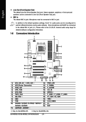
... can be reconfigured to Line Out (Front Speaker Out) jack. GA-M59SLI-S5/GA-M59SLI-S4 Motherboard - 24 - Stereo speakers, earphone or front surround speakers can be connected to perform different functions via the audio software. Only for GA-M59SLI-S5. channel audio setup steps for detailed software configuration information. ... 10) SATAII0 / SATAII1 /S ATAII2 / SATAII3 / 21) C I SATAII4 / SATAII5 22) BAT 11) JSATAII0 / JSATAII1 Only for GA-M59SLI-S4. Please refer to the default Mic In jack ( ). Only microphones still MUST be connected to MIC In jack. MIC In The default MIC...
... can be reconfigured to Line Out (Front Speaker Out) jack. GA-M59SLI-S5/GA-M59SLI-S4 Motherboard - 24 - Stereo speakers, earphone or front surround speakers can be connected to perform different functions via the audio software. Only for GA-M59SLI-S5. channel audio setup steps for detailed software configuration information. ... 10) SATAII0 / SATAII1 /S ATAII2 / SATAII3 / 21) C I SATAII4 / SATAII5 22) BAT 11) JSATAII0 / JSATAII1 Only for GA-M59SLI-S4. Please refer to the default Mic In jack ( ). Only microphones still MUST be connected to MIC In jack. MIC In The default MIC...
Manual
Page 25
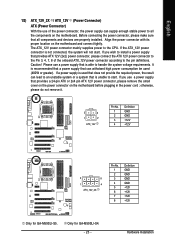
...a 24-pin ATX or 2x4 pin ATX 12V power connector, please remove the small cover on the power connector on the motherboard and connect tightly. Hardware Installation Before connecting the power connector, please make sure that provides ATX 12V (2x2) power connector,... GND GND GND GND +12V +12V +12V +12V Only for GA-M59SLI-S4. - 25 - Only for GA-M59SLI-S5. If you wish to install a power supply that all the components on the motherboard. Align the power connector with its proper location on the motherboard before plugging in the power cord ; If you use a power supply...
...a 24-pin ATX or 2x4 pin ATX 12V power connector, please remove the small cover on the power connector on the motherboard and connect tightly. Hardware Installation Before connecting the power connector, please make sure that provides ATX 12V (2x2) power connector,... GND GND GND GND +12V +12V +12V +12V Only for GA-M59SLI-S4. - 25 - Only for GA-M59SLI-S5. If you wish to install a power supply that all the components on the motherboard. Align the power connector with its proper location on the motherboard before plugging in the power cord ; If you use a power supply...
Manual
Page 26
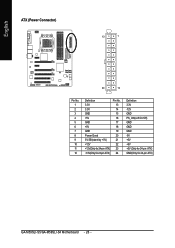
English ATX (Power Connector) 13 1 24 12 Pin No. 1 2 3 4 5 6 7 8 9 10 11 12 Definition 3.3V 3.3V GND +5V GND +5V GND Power Good 5V SB(stand by +5V) +12V +12V(Only for 24-pin ATX) 3.3V(Only for 24-pin ATX) Pin No. 13 14 15 16 17 18 19 20 21 22 23 24 Definition 3.3V -12V GND PS_ON(soft On/Off) GND GND GND -5V +5V +5V +5V (Only for 24-pin ATX) GND(Only for 24-pin ATX) GA-M59SLI-S5/GA-M59SLI-S4 Motherboard - 26 -
English ATX (Power Connector) 13 1 24 12 Pin No. 1 2 3 4 5 6 7 8 9 10 11 12 Definition 3.3V 3.3V GND +5V GND +5V GND Power Good 5V SB(stand by +5V) +12V +12V(Only for 24-pin ATX) 3.3V(Only for 24-pin ATX) Pin No. 13 14 15 16 17 18 19 20 21 22 23 24 Definition 3.3V -12V GND PS_ON(soft On/Off) GND GND GND -5V +5V +5V +5V (Only for 24-pin ATX) GND(Only for 24-pin ATX) GA-M59SLI-S5/GA-M59SLI-S4 Motherboard - 26 -
Manual
Page 28
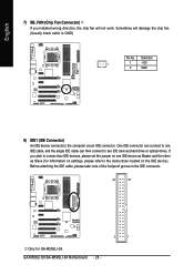
... of the foolproof groove in the IDE connector. 40 39 2 1 Only for information on settings, please refer to the instructions located on the IDE device). GA-M59SLI-S5/GA-M59SLI-S4 Motherboard - 28 - If you installed wrong direction, the chip fan will damage the chip fan. (Usually black cable is GND) Pin No. Definition 1 1 +12V 2 GND...
... of the foolproof groove in the IDE connector. 40 39 2 1 Only for information on settings, please refer to the instructions located on the IDE device). GA-M59SLI-S5/GA-M59SLI-S4 Motherboard - 28 - If you installed wrong direction, the chip fan will damage the chip fan. (Usually black cable is GND) Pin No. Definition 1 1 +12V 2 GND...
Manual
Page 30
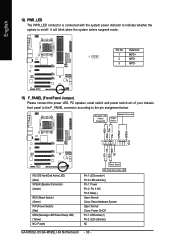
... below. Pin 3: NC Pin 4: Data(-) Open: Normal Close: Reset Hardware System Open: Normal Close: Power On/Off Pin 1: LED anode(+) Pin 2: LED cathode(-) NC GA-M59SLI-S5/GA-M59SLI-S4 Motherboard - 30 - Message LED/ Power/ Sleep LED Speaker Connector Power Switch MSG+ MSG- RESRES+ NC HD (IDE Hard Disk Active LED) (Blue) SPEAK (Speaker Connector) (Amber...
... below. Pin 3: NC Pin 4: Data(-) Open: Normal Close: Reset Hardware System Open: Normal Close: Power On/Off Pin 1: LED anode(+) Pin 2: LED cathode(-) NC GA-M59SLI-S5/GA-M59SLI-S4 Motherboard - 30 - Message LED/ Power/ Sleep LED Speaker Connector Power Switch MSG+ MSG- RESRES+ NC HD (IDE Hard Disk Active LED) (Blue) SPEAK (Speaker Connector) (Amber...


