Manual
Page 1
GA-M55S-S3 (rev. 2.0) AMD Socket AM2 Processor Motherboard User's Manual Rev. 2002 12ME-M55S3R-2002R * The WEEE marking on the product indicates this product must not be disposed of with user's other household waste and must be handed over to a designated collection point for the recycling of waste electrical and electronic equipment!! * The WEEE marking applies only in European Union's member states.
GA-M55S-S3 (rev. 2.0) AMD Socket AM2 Processor Motherboard User's Manual Rev. 2002 12ME-M55S3R-2002R * The WEEE marking on the product indicates this product must not be disposed of with user's other household waste and must be handed over to a designated collection point for the recycling of waste electrical and electronic equipment!! * The WEEE marking applies only in European Union's member states.
Manual
Page 2
Motherboard GA-M55S-S3 (rev. 2.0) Nov. 10, 2006 Motherboard GA-M55S-S3 (rev. 2.0) Nov. 10, 2006
Motherboard GA-M55S-S3 (rev. 2.0) Nov. 10, 2006 Motherboard GA-M55S-S3 (rev. 2.0) Nov. 10, 2006
Manual
Page 4
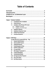
Table of Contents ItemChecklist ...6 OptionalAccessories ...6 GA-M55S-S3 (rev. 2.0) Motherboard Layout 7 Block Diagram ...8 Chapter 1 Hardware Installation 9 1-1 Considerations Prior to Installation 9 1-2 Feature Summary 10 1-3 Installation of the CPU and CPU Cooler 12 1-3-1 Installation of the CPU ...
Table of Contents ItemChecklist ...6 OptionalAccessories ...6 GA-M55S-S3 (rev. 2.0) Motherboard Layout 7 Block Diagram ...8 Chapter 1 Hardware Installation 9 1-1 Considerations Prior to Installation 9 1-2 Feature Summary 10 1-3 Installation of the CPU and CPU Cooler 12 1-3-1 Installation of the CPU ...
Manual
Page 7
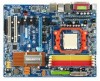
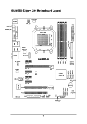
GA-M55S-S3 (rev. 2.0) Motherboard Layout CPU_FAN KB_MS ATX_12V ATX SPDIF_O SPDIFO_OPT Socket AM2 COMA LPT PWR_FAN USB 1394 USB LAN1 Marvell 88E1116 AUDIO PCIE_12V F_AUDIO PCIE_1 CODEC PCIE_16_1 PCIE_2 SPDIF_I CD_IN PCIE_3 PCIE_4 PCI1 IT8716 PCI2 REV: 2.0 FDD DDRII_1 DDRII_2 DDRII_3 DDRII_4 GA-M55S-S3 IDE1 SATAII4 SATAII1 SATAII2 SATAII3 BIOS nVIDIA® nForce 550 CLR_CMOS TSB43AB23 BATTERY F_USB3 F_USB2 F_USB1 F1_1394 F2_1394 CI F_PANEL PWR_LED SYS_FAN - 7 -
GA-M55S-S3 (rev. 2.0) Motherboard Layout CPU_FAN KB_MS ATX_12V ATX SPDIF_O SPDIFO_OPT Socket AM2 COMA LPT PWR_FAN USB 1394 USB LAN1 Marvell 88E1116 AUDIO PCIE_12V F_AUDIO PCIE_1 CODEC PCIE_16_1 PCIE_2 SPDIF_I CD_IN PCIE_3 PCIE_4 PCI1 IT8716 PCI2 REV: 2.0 FDD DDRII_1 DDRII_2 DDRII_3 DDRII_4 GA-M55S-S3 IDE1 SATAII4 SATAII1 SATAII2 SATAII3 BIOS nVIDIA® nForce 550 CLR_CMOS TSB43AB23 BATTERY F_USB3 F_USB2 F_USB1 F1_1394 F2_1394 CI F_PANEL PWR_LED SYS_FAN - 7 -

Manual
Page 9
...please consult a certified computer technician. Hardware Installation English Chapter 1 Hardware Installation 1-1 Considerations Prior to Installation Preparing Your Computer The motherboard contains numerous delicate electronic circuits and components which can lead to damage to system components as well as a result of violating the...Before using the product, please verify that the power supply is best to be an unofficial Gigabyte product. - 9 - Prior to installing the electronic components, please have a problem related to installation, please follow the instructions below: 1.
...please consult a certified computer technician. Hardware Installation English Chapter 1 Hardware Installation 1-1 Considerations Prior to Installation Preparing Your Computer The motherboard contains numerous delicate electronic circuits and components which can lead to damage to system components as well as a result of violating the...Before using the product, please verify that the power supply is best to be an unofficial Gigabyte product. - 9 - Prior to installing the electronic components, please have a problem related to installation, please follow the instructions below: 1.
Manual
Page 10
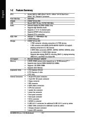
...; 1 CD In connector Š 1 S/PDIF In connector Š 3 USB 2.0/1.1 connectors for additional 6 USB 2.0/1.1 ports by cables Š 1 Chassis Intrusion connector Š 1 power LED connector GA-M55S-S3 (rev. 2.0) Motherboard - 10 - ing connection of 2 IDE devices - 4 SATA 3Gb/s connectors (SATAII1, SATAII2, SATAII3, SATAII4), allow- TSB43AB23 chip Š 3 IEEE1394a ports Storage Š nVIDIA® nForce 550...
...; 1 CD In connector Š 1 S/PDIF In connector Š 3 USB 2.0/1.1 connectors for additional 6 USB 2.0/1.1 ports by cables Š 1 Chassis Intrusion connector Š 1 power LED connector GA-M55S-S3 (rev. 2.0) Motherboard - 10 - ing connection of 2 IDE devices - 4 SATA 3Gb/s connectors (SATAII1, SATAII2, SATAII3, SATAII4), allow- TSB43AB23 chip Š 3 IEEE1394a ports Storage Š nVIDIA® nForce 550...
Manual
Page 11
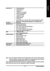
... is installed, the actual memory available for the operating system will depend on the CPU you install. (Note 3) EasyTune functions may vary depending on different motherboards. - 11 -
... is installed, the actual memory available for the operating system will depend on the CPU you install. (Note 3) EasyTune functions may vary depending on different motherboards. - 11 -
Manual
Page 12
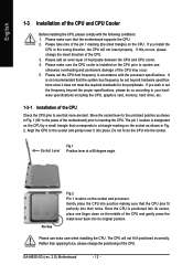
... the required standards for the peripherals. The pin 1 location is not recommended that the motherboard supports the CPU. 2. Please use , otherwise overheating and permanent damage of the motherboard) prior to system use extra care when installing the CPU. GA-M55S-S3 (rev. 2.0) Motherboard - 12 - Please make sure the CPU cooler is positioned into its original position...
... the required standards for the peripherals. The pin 1 location is not recommended that the motherboard supports the CPU. 2. Please use , otherwise overheating and permanent damage of the motherboard) prior to system use extra care when installing the CPU. GA-M55S-S3 (rev. 2.0) Motherboard - 12 - Please make sure the CPU cooler is positioned into its original position...

Manual
Page 13
... heat paste. English 1-3-2 Installation of the CPU Cooler Fig.1 Before installing the CPU cooler, please first add an even layer of heat paste on the motherboard so that either thermal tape rather than heat paste be used for detailed installation instructions).
... heat paste. English 1-3-2 Installation of the CPU Cooler Fig.1 Before installing the CPU cooler, please first add an even layer of heat paste on the motherboard so that either thermal tape rather than heat paste be used for detailed installation instructions).

Manual
Page 14
...please make sure that the computer power is switched off to insert the module, please switch the direction. The motherboard supports DDRII memory modules, whereby BIOS will automatically detect memory capacity and specifications. The memory capacity used . ...comply with each slot. Insert the DIMM memory module vertically into the DIMM socket. It is supported by the motherboard. Notch DDRII Fig.1 The DIMM socket has a notch, so the DIMM memory module can differ with the following... memory of the DIMM sockets to remove the DIMM module. GA-M55S-S3 (rev. 2.0) Motherboard - 14 -
...please make sure that the computer power is switched off to insert the module, please switch the direction. The motherboard supports DDRII memory modules, whereby BIOS will automatically detect memory capacity and specifications. The memory capacity used . ...comply with each slot. Insert the DIMM memory module vertically into the DIMM socket. It is supported by the motherboard. Notch DDRII Fig.1 The DIMM socket has a notch, so the DIMM memory module can differ with the following... memory of the DIMM sockets to remove the DIMM module. GA-M55S-S3 (rev. 2.0) Motherboard - 14 -
Manual
Page 16
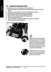
Power on the card are indeed seated in motherboard. 4. Remove your expansion card by the small white-drawable bar. Be sure the metal contacts on the computer, if necessary, setup BIOS utility of expansion .... English 1-5 Installation of Expansion Cards You can also press the latch on the back of the drawable bar as the picture to the left shows. GA-M55S-S3 (rev. 2.0) Motherboard - 16 - Press the expansion card firmly into the computer. 2. Install related driver from the computer. 3. Replace your VGA card is locked by following the...
Power on the card are indeed seated in motherboard. 4. Remove your expansion card by the small white-drawable bar. Be sure the metal contacts on the computer, if necessary, setup BIOS utility of expansion .... English 1-5 Installation of Expansion Cards You can also press the latch on the back of the drawable bar as the picture to the left shows. GA-M55S-S3 (rev. 2.0) Motherboard - 16 - Press the expansion card firmly into the computer. 2. Install related driver from the computer. 3. Replace your VGA card is locked by following the...
Manual
Page 18
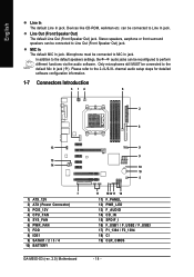
... for detailed software configuration information. 1-7 Connectors Introduction 3 14 6 2 8 13 15 14 7 1) ATX_12V 2) ATX (Power Connector) 3) PCIE_12V 4) CPU_FAN 5) SYS_FAN 6) PWR_FAN 7) FDD 8) IDE1 9) SATAII1 / 2 / 3 / 4 10) BATTERY GA-M55S-S3 (rev. 2.0) Motherboard 9 9 19 10 5 17 1812 11 16 11) F_PANEL 12) PWR_LED 13) F_AUDIO 14) CD_IN 15) SPDIF_I 16) F_USB1 / F_USB2 / F_USB3 17) F1_1394 / F2_1394 18) CI...
... for detailed software configuration information. 1-7 Connectors Introduction 3 14 6 2 8 13 15 14 7 1) ATX_12V 2) ATX (Power Connector) 3) PCIE_12V 4) CPU_FAN 5) SYS_FAN 6) PWR_FAN 7) FDD 8) IDE1 9) SATAII1 / 2 / 3 / 4 10) BATTERY GA-M55S-S3 (rev. 2.0) Motherboard 9 9 19 10 5 17 1812 11 16 11) F_PANEL 12) PWR_LED 13) F_AUDIO 14) CD_IN 15) SPDIF_I 16) F_USB1 / F_USB2 / F_USB3 17) F1_1394 / F2_1394 18) CI...
Manual
Page 19
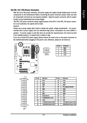
... to handle the system voltage requirements. Please use a power supply that all the components on the motherboard and connect tightly. It is unable to start . Align the power connector with its proper location on the motherboard. If a power supply is used that is recommended that a power supply that can lead to an...(Only for 24-pin ATX) - 19 - If you use a 24-pin ATX power supply, please remove the small cover on the power connector on the motherboard before plugging in the power cord;
... to handle the system voltage requirements. Please use a power supply that all the components on the motherboard and connect tightly. It is unable to start . Align the power connector with its proper location on the motherboard. If a power supply is used that is recommended that a power supply that can lead to an...(Only for 24-pin ATX) - 19 - If you use a 24-pin ATX power supply, please remove the small cover on the power connector on the motherboard before plugging in the power cord;
Manual
Page 20
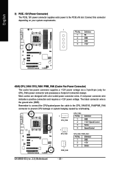
... : Pin No. Most coolers are designed with color-coded power connector wires. The black connector wire is the ground wire (GND). Definition 1 GND 2 +12V 3 Sense GA-M55S-S3 (rev. 2.0) Motherboard - 20 - Definition 1 NC 2 GND 3 GND 4 +12V 4/5/6) CPU_FAN / SYS_FAN / PWR_FAN (Cooler Fan Power Connector) The cooler fan power connector supplies a +12V power voltage via a 3-pin...
... : Pin No. Most coolers are designed with color-coded power connector wires. The black connector wire is the ground wire (GND). Definition 1 GND 2 +12V 3 Sense GA-M55S-S3 (rev. 2.0) Motherboard - 20 - Definition 1 NC 2 GND 3 GND 4 +12V 4/5/6) CPU_FAN / SYS_FAN / PWR_FAN (Cooler Fan Power Connector) The cooler fan power connector supplies a +12V power voltage via a 3-pin...
Manual
Page 22
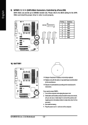
... 4 GND 1 5 RXN 6 RXP 7 7 GND 10) BATTERY Danger of used batteries according to 300MB/s transfer rate. If you can provide up to the manufacturer's instructions. GA-M55S-S3 (rev. 2.0) Motherboard - 22 - Plug the power cord in order to make them short for the SATA 3Gb/s and install the proper driver in and turn on the...
... 4 GND 1 5 RXN 6 RXP 7 7 GND 10) BATTERY Danger of used batteries according to 300MB/s transfer rate. If you can provide up to the manufacturer's instructions. GA-M55S-S3 (rev. 2.0) Motherboard - 22 - Plug the power cord in order to make them short for the SATA 3Gb/s and install the proper driver in and turn on the...
Manual
Page 24
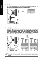
... 4 NC 5 Line Out (R) 6 NC 7 NC 8 No Pin 9 Line Out (L) 10 NC By default, the audio driver is on page 81 about the software settings. GA-M55S-S3 (rev. 2.0) Motherboard - 24 - Check the pin assignments carefully while you wish to use the front audio function, connect the front panel audio module to this connector, please...
... 4 NC 5 Line Out (R) 6 NC 7 NC 8 No Pin 9 Line Out (L) 10 NC By default, the audio driver is on page 81 about the software settings. GA-M55S-S3 (rev. 2.0) Motherboard - 24 - Check the pin assignments carefully while you wish to use the front audio function, connect the front panel audio module to this connector, please...
Manual
Page 26
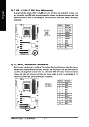
Pin No. Definition 2 10 1 9 1 TPA+ 2 TPA- 3 GND 4 GND 5 TPB+ 6 TPB- 7 No Pin 7 Power (12V) 8 Power (12V) 10 GND GA-M55S-S3 (rev. 2.0) Motherboard - 26 - Check the pin assignment carefully while you connect the IEEE 1394 cable, incorrect connection between the cable and connector will make the device unable ...
Pin No. Definition 2 10 1 9 1 TPA+ 2 TPA- 3 GND 4 GND 5 TPB+ 6 TPB- 7 No Pin 7 Power (12V) 8 Power (12V) 10 GND GA-M55S-S3 (rev. 2.0) Motherboard - 26 - Check the pin assignment carefully while you connect the IEEE 1394 cable, incorrect connection between the cable and connector will make the device unable ...
Manual
Page 28
English GA-M55S-S3 (rev. 2.0) Motherboard - 28 -
English GA-M55S-S3 (rev. 2.0) Motherboard - 28 -
Manual
Page 29
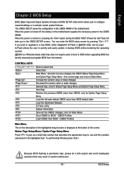
...and easily update or backup BIOS without entering the operating system. @BIOS is a Windows-based utility that may result in the CMOS SRAM of the motherboard. The CMOS SETUP saves the configuration in system malfunction. - 29 - Q-Flash allows the user to DOS before upgrading BIOS but directly download and...from CMOS, only for the highlighted item. You can be used. Status Page Setup Menu / Option Page Setup Menu Press to a new BIOS, either Gigabyte's Q-Flash or @BIOS utility can enter the BIOS setup screen by pressing "Ctrl + F1". If you to the CMOS SRAM. CMOS Profiles Main ...
...and easily update or backup BIOS without entering the operating system. @BIOS is a Windows-based utility that may result in the CMOS SRAM of the motherboard. The CMOS SETUP saves the configuration in system malfunction. - 29 - Q-Flash allows the user to DOS before upgrading BIOS but directly download and...from CMOS, only for the highlighted item. You can be used. Status Page Setup Menu / Option Page Setup Menu Press to a new BIOS, either Gigabyte's Q-Flash or @BIOS utility can enter the BIOS setup screen by pressing "Ctrl + F1". If you to the CMOS SRAM. CMOS Profiles Main ...
Manual
Page 30
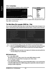
M55S-S3 FAa . . . . :BIOS Setup/Q-Flash, : XpressRecovery2, : Boot Menu 09/28/2006-NV-MCP55S-6A61JG07C-00 Press F12 Boot Menu == Select a Boot First device == Floppy LS120 Hard ... screen. Use arrow keys to select among the items and press to BIOS F12: Load CMOS from BIOS If your motherboard. If you don't find the settings you to accept. GA-M55S-S3 (rev. 2.0) Motherboard - 30 - Award Modular BIOS v6.00PG, An Energy Star Ally Copyright (C) 1984-2006, Award Software, Inc. This action makes the...
M55S-S3 FAa . . . . :BIOS Setup/Q-Flash, : XpressRecovery2, : Boot Menu 09/28/2006-NV-MCP55S-6A61JG07C-00 Press F12 Boot Menu == Select a Boot First device == Floppy LS120 Hard ... screen. Use arrow keys to select among the items and press to BIOS F12: Load CMOS from BIOS If your motherboard. If you don't find the settings you to accept. GA-M55S-S3 (rev. 2.0) Motherboard - 30 - Award Modular BIOS v6.00PG, An Energy Star Ally Copyright (C) 1984-2006, Award Software, Inc. This action makes the...


