Manual
Page 1
GA-M52LT-D3P AM3 socket motherboard for AMD Phenom™ II processor/AMD Athlon™ II processor User's Manual Rev. 3001 12ME-M52LD3P-3001R
GA-M52LT-D3P AM3 socket motherboard for AMD Phenom™ II processor/AMD Athlon™ II processor User's Manual Rev. 3001 12ME-M52LD3P-3001R
Manual
Page 2
Motherboard GA-M52LT-D3P Jan. 10, 2011 Motherboard GA-M52LT-D3P Jan. 10, 2011
Motherboard GA-M52LT-D3P Jan. 10, 2011 Motherboard GA-M52LT-D3P Jan. 10, 2011

Manual
Page 3
...this manual may be made by copyright laws and is 1.0. For example, "REV: 1.0" means the revision of the motherboard is the property of the product, read the Quick Installation Guide included with the product. For detailed product information...the use of this manual is protected by GIGABYTE without GIGABYTE's prior written permission. For product-related information, check on our website at: http://www.gigabyte.com Identifying Your Motherboard Revision The revision number on your motherboard revision before updating motherboard BIOS, drivers, or when looking for technical ...
...this manual may be made by copyright laws and is 1.0. For example, "REV: 1.0" means the revision of the motherboard is the property of the product, read the Quick Installation Guide included with the product. For detailed product information...the use of this manual is protected by GIGABYTE without GIGABYTE's prior written permission. For product-related information, check on our website at: http://www.gigabyte.com Identifying Your Motherboard Revision The revision number on your motherboard revision before updating motherboard BIOS, drivers, or when looking for technical ...
Manual
Page 4
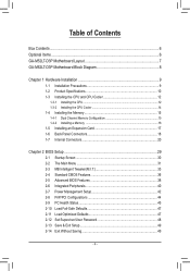
Table of Contents Box Contents...6 Optional Items...6 GA-M52LT-D3P Motherboard Layout 7 GA-M52LT-D3P Motherboard Block Diagram 8 Chapter 1 Hardware Installation 9 1-1 Installation Precautions 9 1-2 Product Specifications 10 1-3 Installing the CPU and CPU Cooler 12 1-3-1 Installing the CPU 12 1-3-2 Installing the CPU Cooler ...
Table of Contents Box Contents...6 Optional Items...6 GA-M52LT-D3P Motherboard Layout 7 GA-M52LT-D3P Motherboard Block Diagram 8 Chapter 1 Hardware Installation 9 1-1 Installation Precautions 9 1-2 Product Specifications 10 1-3 Installing the CPU and CPU Cooler 12 1-3-1 Installing the CPU 12 1-3-2 Installing the CPU Cooler ...
Manual
Page 6
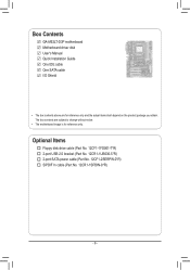
Box Contents GA-M52LT-D3P motherboard Motherboard driver disk User's Manual Quick Installation Guide One IDE cable One SATA cable I/O Shield • The box contents above are subject to change without notice. • The motherboard image is for reference only and the actual items shall depend on the product package you obtain. The box contents are for reference only. Optional Items Floppy disk drive cable (Part No. 12CF1-1FD001-7*R) 2-port USB 2.0 bracket (Part No. 12CR1-1UB030-5*R) 2-port SATA power cable (Part No. 12CF1-2SERPW-0*R) S/PDIF In cable (Part No. 12CR1-1SPDIN-0*R) - 6 -
Box Contents GA-M52LT-D3P motherboard Motherboard driver disk User's Manual Quick Installation Guide One IDE cable One SATA cable I/O Shield • The box contents above are subject to change without notice. • The motherboard image is for reference only and the actual items shall depend on the product package you obtain. The box contents are for reference only. Optional Items Floppy disk drive cable (Part No. 12CF1-1FD001-7*R) 2-port USB 2.0 bracket (Part No. 12CR1-1UB030-5*R) 2-port SATA power cable (Part No. 12CF1-2SERPW-0*R) S/PDIF In cable (Part No. 12CR1-1SPDIN-0*R) - 6 -
Manual
Page 7
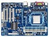
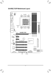
GA-M52LT-D3P Motherboard Layout KB_MS ATX_12V Socket AM3 COAXIAL LPT COMA R_USB USB_LAN CPU_FAN AUDIO F_AUDIO PCIEX16 GA-M52LT-D3P SPDIF_O Realtek PCIEX1_1 RTL8201EL PCIEX1_2 BAT CODEC PCI1 CLR_CMOS CD_IN PCI2 SPDIF_I PCI3 NVIDIA® nForce 520LE iTE IT8720 PCI4 M_BIOS B_BIOS F_PANEL FDD SYS_FAN F_USB2 F_USB1 DDR3_1 DDR3_2 DDR3_3 DDR3_4 PWR_FAN ATX IDE SATA2_1 SATA2_0 - 7 -
GA-M52LT-D3P Motherboard Layout KB_MS ATX_12V Socket AM3 COAXIAL LPT COMA R_USB USB_LAN CPU_FAN AUDIO F_AUDIO PCIEX16 GA-M52LT-D3P SPDIF_O Realtek PCIEX1_1 RTL8201EL PCIEX1_2 BAT CODEC PCI1 CLR_CMOS CD_IN PCI2 SPDIF_I PCI3 NVIDIA® nForce 520LE iTE IT8720 PCI4 M_BIOS B_BIOS F_PANEL FDD SYS_FAN F_USB2 F_USB1 DDR3_1 DDR3_2 DDR3_3 DDR3_4 PWR_FAN ATX IDE SATA2_1 SATA2_0 - 7 -
Manual
Page 8
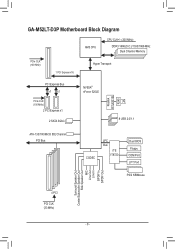
GA-M52LT-D3P Motherboard Block Diagram AM3 CPU CPU CLK+/- (200 MHz) DDR3 1666(O.C.)/1333/1066 MHz Dual Channel Memory PCIe CLK (100 MHz) 1 PCI Express x16 Hyper Transport PCI Express Bus x1 x1 PCIe CLK (100 MHz) 2 PCI Express x1 2 SATA 3Gb/s NVIDIA® nForce 520LE Realtek RTL8201EL RJ45 LAN 8 USB 2.0/1.1 ATA-133/100/66/33 IDE Channel PCI Bus CODEC LPC Bus iTE IT8720 Dual BIOS Floppy COM Port LPT Port PS/2 KB/Mouse Surround Speaker Out Center/Subwoofer Speaker Out Side Speaker Out MIC Line Out Line In S/PDIF In S/PDIF Out 4 PCI PCI CLK (33 MHz) - 8 -
GA-M52LT-D3P Motherboard Block Diagram AM3 CPU CPU CLK+/- (200 MHz) DDR3 1666(O.C.)/1333/1066 MHz Dual Channel Memory PCIe CLK (100 MHz) 1 PCI Express x16 Hyper Transport PCI Express Bus x1 x1 PCIe CLK (100 MHz) 2 PCI Express x1 2 SATA 3Gb/s NVIDIA® nForce 520LE Realtek RTL8201EL RJ45 LAN 8 USB 2.0/1.1 ATA-133/100/66/33 IDE Channel PCI Bus CODEC LPC Bus iTE IT8720 Dual BIOS Floppy COM Port LPT Port PS/2 KB/Mouse Surround Speaker Out Center/Subwoofer Speaker Out Side Speaker Out MIC Line Out Line In S/PDIF In S/PDIF Out 4 PCI PCI CLK (33 MHz) - 8 -

Manual
Page 9
...do not have an ESD wrist strap, keep your hands dry and first touch a metal object to eliminate static electricity. • Prior to installing the motherboard, please have a problem related to the use of the product, please consult a certified computer technician. - 9 - Hardware Installation These stickers are required...system components as well as physical harm to the user. • If you are connected tightly and securely. • When handling the motherboard, avoid touching any installation steps or have it on top of an antistatic pad or within the computer casing. • Do not ...
...do not have an ESD wrist strap, keep your hands dry and first touch a metal object to eliminate static electricity. • Prior to installing the motherboard, please have a problem related to the use of the product, please consult a certified computer technician. - 9 - Hardware Installation These stickers are required...system components as well as physical harm to the user. • If you are connected tightly and securely. • When handling the motherboard, avoid touching any installation steps or have it on top of an antistatic pad or within the computer casing. • Do not ...

Manual
Page 11
...;Š Support for Xpress Install ŠŠ Support for Xpress Recovery2 ŠŠ Support for EasyTune * Available functions in EasyTune may differ by motherboard model. ŠŠ Support for Auto Green ŠŠ Support for ON/OFF Charge Bundled Software ŠŠ Norton Internet Security (OEM version...System ŠŠ Support for Microsoft® Windows 7/Vista/XP Form Factor ŠŠ ATX Form Factor; 30.5cm x 21.6cm * GIGABYTE reserves the right to make any changes to the product specifications and product-related information without prior notice. - 11 -
...;Š Support for Xpress Install ŠŠ Support for Xpress Recovery2 ŠŠ Support for EasyTune * Available functions in EasyTune may differ by motherboard model. ŠŠ Support for Auto Green ŠŠ Support for ON/OFF Charge Bundled Software ŠŠ Norton Internet Security (OEM version...System ŠŠ Support for Microsoft® Windows 7/Vista/XP Form Factor ŠŠ ATX Form Factor; 30.5cm x 21.6cm * GIGABYTE reserves the right to make any changes to the product specifications and product-related information without prior notice. - 11 -

Manual
Page 12
It is not recommended that the motherboard supports the CPU. (Go to GIGABYTE's website for the peripherals. The CPU cannot be set the frequency beyond hardware specifications since it does not meet the standard requirements for the latest ...
It is not recommended that the motherboard supports the CPU. (Go to GIGABYTE's website for the peripherals. The CPU cannot be set the frequency beyond hardware specifications since it does not meet the standard requirements for the latest ...

Manual
Page 13
... the CPU socket and gently insert the CPU into the CPU socket. Hardware Installation Follow the steps below to correctly install the CPU into the motherboard CPU socket. • Before installing the CPU, make sure to turn off the computer and unplug the power cord from the power outlet to prevent...
... the CPU socket and gently insert the CPU into the CPU socket. Hardware Installation Follow the steps below to correctly install the CPU into the motherboard CPU socket. • Before installing the CPU, make sure to turn off the computer and unplug the power cord from the power outlet to prevent...

Manual
Page 14
1-3-2 Installing the CPU Cooler Follow the steps below to correctly install the CPU cooler on the CPU. (The following procedure uses the GIGABYTE cooler as the picture above shows) to lock into place. (Refer to your CPU cooler installation manual for instructions on installing the cooler.) Step 5: Finally, ... CPU. Step 2: Place the CPU cooler on the CPU. Hardware Installation - 14 - Inadequately removing the CPU cooler may adhere to the mounting lug on the motherboard.
1-3-2 Installing the CPU Cooler Follow the steps below to correctly install the CPU cooler on the CPU. (The following procedure uses the GIGABYTE cooler as the picture above shows) to lock into place. (Refer to your CPU cooler installation manual for instructions on installing the cooler.) Step 5: Finally, ... CPU. Step 2: Place the CPU cooler on the CPU. Hardware Installation - 14 - Inadequately removing the CPU cooler may adhere to the mounting lug on the motherboard.

Manual
Page 15
DDR3_1 DDR3_2 DDR3_3 DDR3_4 Due to GIGABYTE's website for optimum performance. - 15 - When enabling Dual Channel mode with two or four memory modules, it is installed. 2. Hardware Installation It is installed, the ... will double the original memory bandwidth. The four DDR3 memory sockets are unable to insert the memory, switch the direction. 1-4-1 Dual Channel Memory Configuration This motherboard provides four DDR3 memory sockets and supports Dual Channel Technology. Enabling Dual Channel memory mode will automatically detect the specifications and capacity of the memory...
DDR3_1 DDR3_2 DDR3_3 DDR3_4 Due to GIGABYTE's website for optimum performance. - 15 - When enabling Dual Channel mode with two or four memory modules, it is installed. 2. Hardware Installation It is installed, the ... will double the original memory bandwidth. The four DDR3 memory sockets are unable to insert the memory, switch the direction. 1-4-1 Dual Channel Memory Configuration This motherboard provides four DDR3 memory sockets and supports Dual Channel Technology. Enabling Dual Channel memory mode will automatically detect the specifications and capacity of the memory...

Manual
Page 16
... memory and insert it can only fit in the memory sockets. Follow the steps below to the memory module. Place the memory module on this motherboard. Hardware Installation - 16 - 1-4-2 Installing a Memory Before installing a memory module, make sure to turn off the computer and unplug the power cord from the power outlet...
... memory and insert it can only fit in the memory sockets. Follow the steps below to the memory module. Place the memory module on this motherboard. Hardware Installation - 16 - 1-4-2 Installing a Memory Before installing a memory module, make sure to turn off the computer and unplug the power cord from the power outlet...
Manual
Page 17
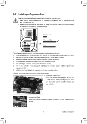
... turn off the computer and unplug the power cord from the power outlet before you begin to install an expansion card: • Make sure the motherboard supports the expansion card. Hardware Installation Locate an expansion slot that came with the expansion card in the slot and does not rock. • Removing...
... turn off the computer and unplug the power cord from the power outlet before you begin to install an expansion card: • Make sure the motherboard supports the expansion card. Hardware Installation Locate an expansion slot that came with the expansion card in the slot and does not rock. • Removing...

Manual
Page 18
... The USB port supports the USB 2.0/1.1 specification. The following describes the states of the LAN port LEDs. Do not rock it straight out from the motherboard. • When removing the cable, pull it side to side to a back panel connector, first remove the cable from your audio system provides a coaxial digital...
... The USB port supports the USB 2.0/1.1 specification. The following describes the states of the LAN port LEDs. Do not rock it straight out from the motherboard. • When removing the cable, pull it side to side to a back panel connector, first remove the cable from your audio system provides a coaxial digital...

Manual
Page 20
..., make sure your devices are compliant with the connectors you wish to connect. • Before installing the devices, be sure to the connector on the motherboard. Unplug the power cord from the power outlet to prevent damage to the devices. • After installing the device and before connecting external devices: •...
..., make sure your devices are compliant with the connectors you wish to connect. • Before installing the devices, be sure to the connector on the motherboard. Unplug the power cord from the power outlet to prevent damage to the devices. • After installing the device and before connecting external devices: •...

Manual
Page 21
... connector in the correct orientation. The power connector possesses a foolproof design. If the 12V power connector is turned off and all the components on the motherboard. To meet expansion requirements, it is used (500W or greater). Connect the power supply cable to the CPU. 1/2) ATX_12V/ATX (2x2 12V Power Connector and...
... connector in the correct orientation. The power connector possesses a foolproof design. If the 12V power connector is turned off and all the components on the motherboard. To meet expansion requirements, it is used (500W or greater). Connect the power supply cable to the CPU. 1/2) ATX_12V/ATX (2x2 12V Power Connector and...

Manual
Page 22
... No. 1 2 3 Definition GND +12V / Speed Control Sense PWR_FAN: Pin No. 3/4/5) CPU_FAN/SYS_FAN/PWR_FAN (Fan Headers) The motherboard has a 4-pin CPU fan header (CPU_FAN), a 3-pin system fan header (SYS_FAN), and a 3-pin power fan header (PWR_FAN). The motherboard supports CPU fan speed control, which requires the use of the cable is recommended that a system...
... No. 1 2 3 Definition GND +12V / Speed Control Sense PWR_FAN: Pin No. 3/4/5) CPU_FAN/SYS_FAN/PWR_FAN (Fan Headers) The motherboard has a 4-pin CPU fan header (CPU_FAN), a 3-pin system fan header (SYS_FAN), and a 3-pin power fan header (PWR_FAN). The motherboard supports CPU fan speed control, which requires the use of the cable is recommended that a system...

Manual
Page 25
Incorrect connection between the module connector and the motherboard header will be present on both of the motherboard header. Definition For AC'97 Front Panel Audio: Pin No. If you want to mute the back panel audio (only supported when using an HD ...
Incorrect connection between the module connector and the motherboard header will be present on both of the motherboard header. Definition For AC'97 Front Panel Audio: Pin No. If you want to mute the back panel audio (only supported when using an HD ...


