Manual
Page 1
GA-M52L-S3P AM2+/AM2 socket motherboard for AMD PhenomTM FX processor/AMD PhenomTM X4 processor/ AMD PhenomTM X3 processor/AMD AthlonTM X2 processor/ AMD AthlonTM processor/AMD SempronTM X2 processor/ AMD SempronTM processor User's Manual Rev. 1002 12ME-M52LS3P-1002R
GA-M52L-S3P AM2+/AM2 socket motherboard for AMD PhenomTM FX processor/AMD PhenomTM X4 processor/ AMD PhenomTM X3 processor/AMD AthlonTM X2 processor/ AMD AthlonTM processor/AMD SempronTM X2 processor/ AMD SempronTM processor User's Manual Rev. 1002 12ME-M52LS3P-1002R
Manual
Page 2
Motherboard GA-M52L-S3P Jan. 15, 2009 Motherboard GA-M52L-S3P Jan. 15, 2009
Motherboard GA-M52L-S3P Jan. 15, 2009 Motherboard GA-M52L-S3P Jan. 15, 2009
Manual
Page 3
... respective owners. For product-related information, check on our website at: http://www.gigabyte.com.tw Identifying Your Motherboard Revision The revision number on your motherboard revision before updating motherboard BIOS, drivers, or when looking for technical information. Disclaimer Information in this manual...Guide page on how to the specifications and features in any form or by copyright laws and is 1.0. Check your motherboard looks like this product, GIGABYTE provides the following types of documentations: For quick set-up of this : "REV: X.X." All rights...
... respective owners. For product-related information, check on our website at: http://www.gigabyte.com.tw Identifying Your Motherboard Revision The revision number on your motherboard revision before updating motherboard BIOS, drivers, or when looking for technical information. Disclaimer Information in this manual...Guide page on how to the specifications and features in any form or by copyright laws and is 1.0. Check your motherboard looks like this product, GIGABYTE provides the following types of documentations: For quick set-up of this : "REV: X.X." All rights...
Manual
Page 4
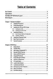
Table of Contents Box Contents ...6 OptionalItems...6 GA-M52L-S3P Motherboard Layout 7 Block Diagram...8 Chapter 1 Hardware Installation 9 1-1 Installation Precautions 9 1-2 Product Specifications 10 1-3 Installing the CPU and CPU Cooler 12 1-3-1 Installing the CPU 12 1-3-2 Installing the CPU ...
Table of Contents Box Contents ...6 OptionalItems...6 GA-M52L-S3P Motherboard Layout 7 Block Diagram...8 Chapter 1 Hardware Installation 9 1-1 Installation Precautions 9 1-2 Product Specifications 10 1-3 Installing the CPU and CPU Cooler 12 1-3-1 Installing the CPU 12 1-3-2 Installing the CPU ...
Manual
Page 6
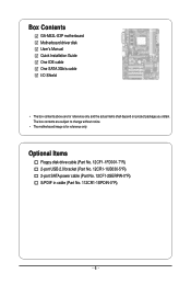
Box Contents GA-M52L-S3P motherboard Motherboard driver disk User's Manual Quick Installation Guide One IDE cable One SATA 3Gb/s cable I/O Shield • The box contents above are subject to change without notice. • The motherboard image is for reference only and the actual items shall depend on product package you obtain. The box contents are for...
Box Contents GA-M52L-S3P motherboard Motherboard driver disk User's Manual Quick Installation Guide One IDE cable One SATA 3Gb/s cable I/O Shield • The box contents above are subject to change without notice. • The motherboard image is for reference only and the actual items shall depend on product package you obtain. The box contents are for...
Manual
Page 9
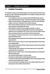
...as a result of the product, please consult a certified computer technician. - 9 - Chapter 1 Hardware Installation 1-1 Installation Precautions The motherboard contains numerous delicate electronic circuits and components which can lead to damage to system components as well as physical harm to the user. &#...electrostatic shielding container. • Before unplugging the power supply cable from the power outlet before installing or removing the motherboard or other hardware components. • When connecting hardware components to the internal connectors on the computer power during the...
...as a result of the product, please consult a certified computer technician. - 9 - Chapter 1 Hardware Installation 1-1 Installation Precautions The motherboard contains numerous delicate electronic circuits and components which can lead to damage to system components as well as physical harm to the user. &#...electrostatic shielding container. • Before unplugging the power supply cable from the power outlet before installing or removing the motherboard or other hardware components. • When connecting hardware components to the internal connectors on the computer power during the...
Manual
Page 10
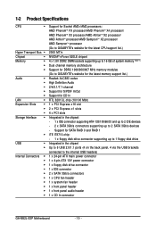
... processor/AMD AthlonTM X2 processor/ AMD AthlonTM processor/AMD SempronTM X2 processor/ AMD SempronTM processor (Go to GIGABYTE's website for the latest CPU support list.) 2000 MT/s NVIDIA® nForce 520LE chipset 4 x 1.8V... (Note 1) Dual channel memory architecture Support for DDR2 1066/800/667 MHz memory modules (Go to GIGABYTE's website for the latest memory support list.) Realtek ALC883 codec High Definition Audio 2/4/5.1/7.1-channel Support for S/...CPU fan header 1 x system fan header 1 x front panel header 1 x front panel audio header 1 x CD In connector GA-M52L-S3P Motherboard - 10 -
... processor/AMD AthlonTM X2 processor/ AMD AthlonTM processor/AMD SempronTM X2 processor/ AMD SempronTM processor (Go to GIGABYTE's website for the latest CPU support list.) 2000 MT/s NVIDIA® nForce 520LE chipset 4 x 1.8V... (Note 1) Dual channel memory architecture Support for DDR2 1066/800/667 MHz memory modules (Go to GIGABYTE's website for the latest memory support list.) Realtek ALC883 codec High Definition Audio 2/4/5.1/7.1-channel Support for S/...CPU fan header 1 x system fan header 1 x front panel header 1 x front panel audio header 1 x CD In connector GA-M52L-S3P Motherboard - 10 -
Manual
Page 11
... 2) Whether the CPU/System fan speed control function is supported will depend on the cooler you install. (Note 3) Available functions in EasyTune may differ by motherboard model. - 11 -
... 2) Whether the CPU/System fan speed control function is supported will depend on the cooler you install. (Note 3) Available functions in EasyTune may differ by motherboard model. - 11 -
Manual
Page 12
... Marking Denotes CPU Pin One AM2+/AM2 CPU GA-M52L-S3P Motherboard - 12 - It is not installed, otherwise overheating and damage of the CPU may occur. • Set the CPU host frequency in accordance with the CPU specifications. mended that the motherboard supports the CPU. (Go to GIGABYTE's website for the latest CPU support list.) •...
... Marking Denotes CPU Pin One AM2+/AM2 CPU GA-M52L-S3P Motherboard - 12 - It is not installed, otherwise overheating and damage of the CPU may occur. • Set the CPU host frequency in accordance with the CPU specifications. mended that the motherboard supports the CPU. (Go to GIGABYTE's website for the latest CPU support list.) •...
Manual
Page 13
Make sure that the CPU pins fit perfectly into the motherboard CPU socket. Adjust the CPU orientation if this occurs. - 13 - Hardware Installation CPU Socket Locking Lever Step 1: Completely lift up the CPU socket locking lever. ...
Make sure that the CPU pins fit perfectly into the motherboard CPU socket. Adjust the CPU orientation if this occurs. - 13 - Hardware Installation CPU Socket Locking Lever Step 1: Completely lift up the CPU socket locking lever. ...
Manual
Page 14
...Step 1: Apply an even and thin layer of thermal grease on the motherboard. 1-3-2 Installing the CPU Cooler Follow the steps below to correctly install the CPU cooler on the CPU. (The following procedure uses the GIGABYTE cooler as the picture above shows) to lock into place. (Refer... to your CPU cooler installation manual for instructions on installing the cooler.) Step 5: Finally, attach the power connector of the CPU cooler to the CPU fan header (CPU_FAN) on the surface of the installed CPU. GA-M52L-S3P Motherboard...
...Step 1: Apply an even and thin layer of thermal grease on the motherboard. 1-3-2 Installing the CPU Cooler Follow the steps below to correctly install the CPU cooler on the CPU. (The following procedure uses the GIGABYTE cooler as the picture above shows) to lock into place. (Refer... to your CPU cooler installation manual for instructions on installing the cooler.) Step 5: Finally, attach the power connector of the CPU cooler to the CPU fan header (CPU_FAN) on the surface of the installed CPU. GA-M52L-S3P Motherboard...
Manual
Page 15
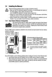
...in only one DDR2 memory module is recommended that memory of the same capacity, brand, speed, and chips be used . (Go to GIGABYTE's website for optimum performance. - 15 - Hardware Installation Dual Channel mode cannot be enabled if only one direction. Enabling Dual Channel memory ... modules have a foolproof design. DDR2_1 DDR2_2 DDR2_3 DDR2_4 Due to insert the memory, switch the direction. 1-4-1 Dual Channel Memory Configuration This motherboard provides four DDR2 memory sockets and supports Dual Channel Technology. DS/SS DS/SS Four Modules DS/SS DS/SS DS/SS DS/SS ...
...in only one DDR2 memory module is recommended that memory of the same capacity, brand, speed, and chips be used . (Go to GIGABYTE's website for optimum performance. - 15 - Hardware Installation Dual Channel mode cannot be enabled if only one direction. Enabling Dual Channel memory ... modules have a foolproof design. DDR2_1 DDR2_2 DDR2_3 DDR2_4 Due to insert the memory, switch the direction. 1-4-1 Dual Channel Memory Configuration This motherboard provides four DDR2 memory sockets and supports Dual Channel Technology. DS/SS DS/SS Four Modules DS/SS DS/SS DS/SS DS/SS ...
Manual
Page 16
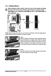
... inserted. Spread the retaining clips at both ends of the memory module. Step 2: The clips at both ends of the memory, push down on this motherboard. GA-M52L-S3P Motherboard - 16 - DDR2 DIMMs are not compatible to DDR DIMMs. Be sure to correctly install your fingers on the socket. As indicated in the picture on...
... inserted. Spread the retaining clips at both ends of the memory module. Step 2: The clips at both ends of the memory, push down on this motherboard. GA-M52L-S3P Motherboard - 16 - DDR2 DIMMs are not compatible to DDR DIMMs. Be sure to correctly install your fingers on the socket. As indicated in the picture on...

Manual
Page 17
... turn off the computer and unplug the power cord from the power outlet before you begin to install an expansion card: • Make sure the motherboard supports the expansion card. Locate an expansion slot that came with the expansion card in the slot and does not rock. • Removing the Card...
... turn off the computer and unplug the power cord from the power outlet before you begin to install an expansion card: • Make sure the motherboard supports the expansion card. Locate an expansion slot that came with the expansion card in the slot and does not rock. • Removing the Card...
Manual
Page 18
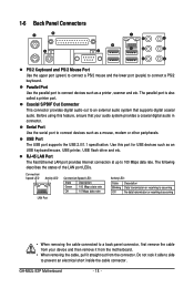
.... The parallel port is occurring • When removing the cable connected to an external audio system that your device and then remove it from the motherboard. • When removing the cable, pull it side to side to connect devices such as a printer, scanner and etc. Coaxial S/PDIF Out Connector This connector.... The following describes the states of the LAN port LEDs. Parallel Port Use the parallel port to prevent an electrical short inside the cable connector. GA-M52L-S3P Motherboard - 18 -
.... The parallel port is occurring • When removing the cable connected to an external audio system that your device and then remove it from the motherboard. • When removing the cable, pull it side to side to connect devices such as a printer, scanner and etc. Coaxial S/PDIF Out Connector This connector.... The following describes the states of the LAN port LEDs. Parallel Port Use the parallel port to prevent an electrical short inside the cable connector. GA-M52L-S3P Motherboard - 18 -
Manual
Page 20
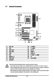
GA-M52L-S3P Motherboard - 20 - 1-7 Internal Connectors 1 3 11 14 9 17 12 13 1) ATX_12V 2) ATX 3) CPU_FAN 4) SYS_FAN 5) FDD 6) IDE 7) SATA2_0 / 1 8) PWR_LED 9) BATTERY 2 6 15 7 5 16 4 8 10 10) F_PANEL 11) F_AUDIO 12) CD_IN 13) SPDIF_I 14) SPDIF_O 15) F_USB1 / F_USB2 16) CI 17) CLR_CMOS Read the following guidelines before turning on the motherboard. Unplug the power cord from the...
GA-M52L-S3P Motherboard - 20 - 1-7 Internal Connectors 1 3 11 14 9 17 12 13 1) ATX_12V 2) ATX 3) CPU_FAN 4) SYS_FAN 5) FDD 6) IDE 7) SATA2_0 / 1 8) PWR_LED 9) BATTERY 2 6 15 7 5 16 4 8 10 10) F_PANEL 11) F_AUDIO 12) CD_IN 13) SPDIF_I 14) SPDIF_O 15) F_USB1 / F_USB2 16) CI 17) CLR_CMOS Read the following guidelines before turning on the motherboard. Unplug the power cord from the...
Manual
Page 21
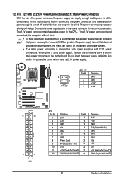
... supply cable into pins under the protective cover when using a 2x12 power supply, remove the protective cover from the main power connector on the motherboard. If the 12V power connector is not connected, the computer will not start. • To meet expansion requirements, it is recommended that a...be used (500W or greater). The power connector possesses a foolproof design. If a power supply is turned off and all the components on the motherboard. 1/2) ATX_12V/ATX (2x2 12V Power Connector and 2x12 Main Power Connector) With the use of the power connector, the power supply can supply ...
... supply cable into pins under the protective cover when using a 2x12 power supply, remove the protective cover from the main power connector on the motherboard. If the 12V power connector is not connected, the computer will not start. • To meet expansion requirements, it is recommended that a...be used (500W or greater). The power connector possesses a foolproof design. If a power supply is turned off and all the components on the motherboard. 1/2) ATX_12V/ATX (2x2 12V Power Connector and 2x12 Main Power Connector) With the use of the power connector, the power supply can supply ...
Manual
Page 22
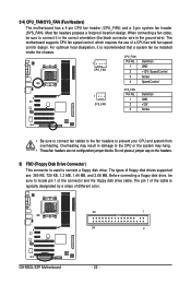
...360 KB, 720 KB, 1.2 MB, 1.44 MB, and 2.88 MB. The types of a CPU fan with fan speed control design. The motherboard supports CPU fan speed control, which requires the use of floppy disk drives supported are not configuration jumper blocks. When connecting a fan cable, be ... jumper cap on the headers. 5) FDD (Floppy Disk Drive Connector) This connector is typically designated by a stripe of different color. 33 1 34 2 GA-M52L-S3P Motherboard - 22 - The pin 1 of the connector and the floppy disk drive cable. Before connecting a floppy disk drive, be sure to prevent your CPU ...
...360 KB, 720 KB, 1.2 MB, 1.44 MB, and 2.88 MB. The types of a CPU fan with fan speed control design. The motherboard supports CPU fan speed control, which requires the use of floppy disk drives supported are not configuration jumper blocks. When connecting a fan cable, be ... jumper cap on the headers. 5) FDD (Floppy Disk Drive Connector) This connector is typically designated by a stripe of different color. 33 1 34 2 GA-M52L-S3P Motherboard - 22 - The pin 1 of the connector and the floppy disk drive cable. Before connecting a floppy disk drive, be sure to prevent your CPU ...
Manual
Page 24
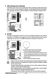
... is operating. The LED is off your computer and unplug the power cord before replacing the battery. • Replace the battery with local environmental regulations. GA-M52L-S3P Motherboard - 24 - Pin No. 1 2 3 Definition MPD+ MPDMPD- 1 System Status LED S0 On S1 Blinking S3/S4/S5 Off 9) BATTERY The battery provides power to indicate system...
... is operating. The LED is off your computer and unplug the power cord before replacing the battery. • Replace the battery with local environmental regulations. GA-M52L-S3P Motherboard - 24 - Pin No. 1 2 3 Definition MPD+ MPDMPD- 1 System Status LED S0 On S1 Blinking S3/S4/S5 Off 9) BATTERY The battery provides power to indicate system...
Manual
Page 26
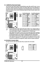
Incorrect connection between the module connector and the motherboard header will be present on both of the front and back panel audio connections simultaneously. For HD Front Panel Audio: For AC'97 Front Panel ... connector match the pin assignments of a single plug. If your chassis front panel audio module to the header. Pin No. Definition 1 1 CD-L 2 GND 3 GND 4 CD-R GA-M52L-S3P Motherboard - 26 - Definition Pin No. 11) F_AUDIO (Front Panel Audio Header) The front panel audio header supports Intel High Definition audio (HD) and AC'97 audio...
Incorrect connection between the module connector and the motherboard header will be present on both of the front and back panel audio connections simultaneously. For HD Front Panel Audio: For AC'97 Front Panel ... connector match the pin assignments of a single plug. If your chassis front panel audio module to the header. Pin No. Definition 1 1 CD-L 2 GND 3 GND 4 CD-R GA-M52L-S3P Motherboard - 26 - Definition Pin No. 11) F_AUDIO (Front Panel Audio Header) The front panel audio header supports Intel High Definition audio (HD) and AC'97 audio...


