User Manual
Page 6
... Unit (CPU 14 Step 2: Install Memory Modules 16 Step 3: Install expansion cards 17 Step 4: Connect ribbon cables, cabinet wires and power supply 18 Step 4-1: I/O Back Panel Introduction 18 Step 4-2: Connectors Introduction 20 Chapter 3 BIOS Setup 35 The Main Menu (For example: BIOS Ver. : F6 36 Standard CMOS Features 38 Advanced BIOS Features 40 Integrated Peripherals 41 Power Management Setup 44 PnP/PCI Configurations 45 PC Health Status 46 Frequency/Voltage Control 47 Load Fail-Safe Defaults 48 Load Optimized Defaults 48 GA-K8VM800M Motherboard - 6 -
... Unit (CPU 14 Step 2: Install Memory Modules 16 Step 3: Install expansion cards 17 Step 4: Connect ribbon cables, cabinet wires and power supply 18 Step 4-1: I/O Back Panel Introduction 18 Step 4-2: Connectors Introduction 20 Chapter 3 BIOS Setup 35 The Main Menu (For example: BIOS Ver. : F6 36 Standard CMOS Features 38 Advanced BIOS Features 40 Integrated Peripherals 41 Power Management Setup 44 PnP/PCI Configurations 45 PC Health Status 46 Frequency/Voltage Control 47 Load Fail-Safe Defaults 48 Load Optimized Defaults 48 GA-K8VM800M Motherboard - 6 -
User Manual
Page 8
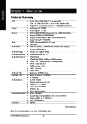
GA-K8VM800M Motherboard - 8 - English Chapter 1 Introduction Features Summary CPU y y Chipset y y Memory y y y y Slots y y On-Board IDE y On-Board Floppy y On-Board Serial ATA y On-Board Peripherals y y y y y y y On-Board VGA y On-Board LAN y y On-Board Sound y y y y y y On-Board SATA RAID y y y y I/O Control y Socket 754 for AMD AlthlonTM 64 processor (K8) 128K L1& 256K / 512K / 1M L2 cache on die , 800MHz FSB Support core frequencies in excess of 1.6 GHz(2800+) and faster Northbridge:VIA K8M800 Southbridge:VIA VT8237 2 184-pin DDR DIMM sockets,...
GA-K8VM800M Motherboard - 8 - English Chapter 1 Introduction Features Summary CPU y y Chipset y y Memory y y y y Slots y y On-Board IDE y On-Board Floppy y On-Board Serial ATA y On-Board Peripherals y y y y y y y On-Board VGA y On-Board LAN y y On-Board Sound y y y y y y On-Board SATA RAID y y y y I/O Control y Socket 754 for AMD AlthlonTM 64 processor (K8) 128K L1& 256K / 512K / 1M L2 cache on die , 800MHz FSB Support core frequencies in excess of 1.6 GHz(2800+) and faster Northbridge:VIA K8M800 Southbridge:VIA VT8237 2 184-pin DDR DIMM sockets,...
User Manual
Page 13
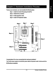
Install I/O Peripherals Cables Step 4 Step 1 Step 2 Step 4 Step 3 Step 4 Congratulations! Install expansion cards Step 4 - Continue with the BIOS/software installation. - 13 - Turn on the power supply or connect the power cable to the power outlet. Install memory modules Step 3 - Hardware Installation Process English Chapter 2 Hardware Installation Process To set up your computer, you must complete the following steps: Step 1 - Install the Central Processing Unit (CPU) Step 2 - You have accomplished the hardware installation!
Install I/O Peripherals Cables Step 4 Step 1 Step 2 Step 4 Step 3 Step 4 Congratulations! Install expansion cards Step 4 - Continue with the BIOS/software installation. - 13 - Turn on the power supply or connect the power cable to the power outlet. Install memory modules Step 3 - Hardware Installation Process English Chapter 2 Hardware Installation Process To set up your computer, you must complete the following steps: Step 1 - Install the Central Processing Unit (CPU) Step 2 - You have accomplished the hardware installation!
User Manual
Page 19
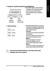
English Parallel Port , Serial Port and VGA Port (LPT/COMA/VGA) This connector supports 1 standard COM port, Parallel Port (25 pin Female) 1 Parallel port and 1 VGA port. Device like printer can be connected to page 27, and contact your nearest dealer for optional SUR_CEN cable. can refer to Serial ports. If you want to enable 6-channel function, you want the detail information for hardware connection. Hardware Installation Process Method1: Connect "Front Speaker" to "Line Out" Connect "Rear Speaker" to...
English Parallel Port , Serial Port and VGA Port (LPT/COMA/VGA) This connector supports 1 standard COM port, Parallel Port (25 pin Female) 1 Parallel port and 1 VGA port. Device like printer can be connected to page 27, and contact your nearest dealer for optional SUR_CEN cable. can refer to Serial ports. If you want to enable 6-channel function, you want the detail information for hardware connection. Hardware Installation Process Method1: Connect "Front Speaker" to "Line Out" Connect "Rear Speaker" to...
User Manual
Page 25
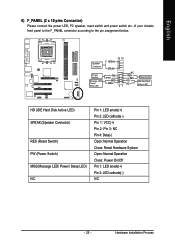
...+ 21 NC RES+ RESHDHD+ Reset Switch IDE Hard Disk Active LED HD (IDE Hard Disk Active LED) SPEAK (Speaker Connector) RES (Reset Switch) PW (Power Switch) MSG(Message LED/ Power/ Sleep LED) NC Pin 1: LED anode(+) Pin 2: LED cathode(-) Pin 1: VCC(+) Pin 2- of your chassis front panel to the F_PANEL connector according to the pin assignment below. Speaker Connector Power Switch Message LED/ Power/ Sleep LED 20 19 SPEAK- Pin 3: NC Pin 4: Data(-) Open: Normal Operation Close: Reset Hardware System Open: Normal Operation Close: Power On/Off Pin 1: LED anode(+) Pin 2: LED cathode(-) NC - 25...
...+ 21 NC RES+ RESHDHD+ Reset Switch IDE Hard Disk Active LED HD (IDE Hard Disk Active LED) SPEAK (Speaker Connector) RES (Reset Switch) PW (Power Switch) MSG(Message LED/ Power/ Sleep LED) NC Pin 1: LED anode(+) Pin 2: LED cathode(-) Pin 1: VCC(+) Pin 2- of your chassis front panel to the F_PANEL connector according to the pin assignment below. Speaker Connector Power Switch Message LED/ Power/ Sleep LED 20 19 SPEAK- Pin 3: NC Pin 4: Data(-) Open: Normal Operation Close: Reset Hardware System Open: Normal Operation Close: Power On/Off Pin 1: LED anode(+) Pin 2: LED cathode(-) NC - 25...

User Manual
Page 27
... 62 Pin No. 1 2 3 4 5 6 Definition Power No Pin SPDIF SPDIFI GND GND 13) CD_IN (CD In Connector) Connect CD-ROM or DVD-ROM audio out to an external Dolby Digital Decoder. Hardware Installation Process English 12) SPDIF_IO (SPDIF In / Out Connector) The SPDIF output is capable of the SPDIF_IO connector. Check the pin assignment carefully while you connect the SPDIF cable, incorrect connection between the cable and connector will make the device unable to work...
... 62 Pin No. 1 2 3 4 5 6 Definition Power No Pin SPDIF SPDIFI GND GND 13) CD_IN (CD In Connector) Connect CD-ROM or DVD-ROM audio out to an external Dolby Digital Decoder. Hardware Installation Process English 12) SPDIF_IO (SPDIF In / Out Connector) The SPDIF output is capable of the SPDIF_IO connector. Check the pin assignment carefully while you connect the SPDIF cable, incorrect connection between the cable and connector will make the device unable to work...

User Manual
Page 38
... Memory Total Memory Wed, May 11 2005 10:40:9 [None] [None] [None] [None] [None] [None] [1.44M, 3.5"] [None] [Disabled] [All, But Keyboard] 640K 127M 128M Item Help Menu Level` Change the day, month, year Sun. The time is 13:00:00. IDE Device Setup. to Sat, determined by the BIOS and is , , , . Manual User can manually input the correct settings Access Mode Use this option for faster system start up . GA-K8VM800M Motherboard...
... Memory Total Memory Wed, May 11 2005 10:40:9 [None] [None] [None] [None] [None] [None] [1.44M, 3.5"] [None] [Disabled] [All, But Keyboard] 640K 127M 128M Item Help Menu Level` Change the day, month, year Sun. The time is 13:00:00. IDE Device Setup. to Sat, determined by the BIOS and is , , , . Manual User can manually input the correct settings Access Mode Use this option for faster system start up . GA-K8VM800M Motherboard...

User Manual
Page 42
... USB mouse support. (Default value) Onboard H/W LAN Enabled Enable onboard LAN function. (Default value) Disabled Disable onboard LAN function. Disabled Disable USB keyboard support. (Default value) USB Mouse Support Enabled Enable USB mouse support. SATA Mode RAID IDE Set onboard SATA mode to RAID. (Default value) Set onboard SATA mode to invoke the boot ROM of the onboard LAN chip. USB 2.0 Controller Disable USB 2.0 host controller if you are not using USB devices. USB 1.1 Controller Disable USB 1.1 host controller if you are not using high speed USB devices...
... USB mouse support. (Default value) Onboard H/W LAN Enabled Enable onboard LAN function. (Default value) Disabled Disable onboard LAN function. Disabled Disable USB keyboard support. (Default value) USB Mouse Support Enabled Enable USB mouse support. SATA Mode RAID IDE Set onboard SATA mode to RAID. (Default value) Set onboard SATA mode to invoke the boot ROM of the onboard LAN chip. USB 2.0 Controller Disable USB 2.0 host controller if you are not using USB devices. USB 1.1 Controller Disable USB 1.1 host controller if you are not using high speed USB devices...
User Manual
Page 44
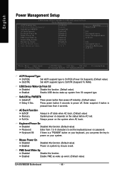
...). (Default value) S3(STR) Set ACPI suspend type to set the keyboard power on the status before AC lost. Enabled Enable PME as wake up system from 1 to 8 characters to S3/STR (Suspend To RAM). Keyboard Power On Disabled Disabled this function. (Default value) Enabled Enable USB device wake up event. (Default value) GA-K8VM800M Motherboard - 44 - Soft-Off by PWRBTN Instant-off Press power button then power off . USB Device Wake-Up From S3 Disabled Disable this function. (Default value) Password Enter from S3 suspend type.
...). (Default value) S3(STR) Set ACPI suspend type to set the keyboard power on the status before AC lost. Enabled Enable PME as wake up system from 1 to 8 characters to S3/STR (Suspend To RAM). Keyboard Power On Disabled Disabled this function. (Default value) Enabled Enable USB device wake up event. (Default value) GA-K8VM800M Motherboard - 44 - Soft-Off by PWRBTN Instant-off Press power button then power off . USB Device Wake-Up From S3 Disabled Disable this function. (Default value) Password Enter from S3 suspend type.
User Manual
Page 47
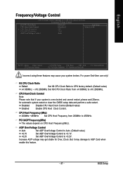
... your system broken. AGP OverVoltage Control Auto Set AGP OverVoltage Control to Auto. (Default value) +0.1V Set AGP OverVoltage Control to +0.1V. +0.2V Set AGP OverVoltage Control to x10 2000Mhz. Increase AGP voltage may get stable for automatic system restart or clear the CMOS setup data and perform a safe restart. English Frequency/Voltage Control CMOS Setup Utility-Copyright (C) 1984-2005 Award Software Frequency/Voltage Control K8 CPU Clock Ratio CPU Host Clock Control x CPU Host Frequency PCI/AGP Frequency AGP OverVoltage Control [Default] [Disabled] 200 33/66 Audo...
... your system broken. AGP OverVoltage Control Auto Set AGP OverVoltage Control to Auto. (Default value) +0.1V Set AGP OverVoltage Control to +0.1V. +0.2V Set AGP OverVoltage Control to x10 2000Mhz. Increase AGP voltage may get stable for automatic system restart or clear the CMOS setup data and perform a safe restart. English Frequency/Voltage Control CMOS Setup Utility-Copyright (C) 1984-2005 Award Software Frequency/Voltage Control K8 CPU Clock Ratio CPU Host Clock Control x CPU Host Frequency PCI/AGP Frequency AGP OverVoltage Control [Default] [Disabled] 200 33/66 Audo...
User Manual
Page 49
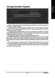
...BIOS Setup Type the password, up to confirm the password. A message "PASSWORD DISABLED" will appear to assist you in Advance BIOS Features Menu, you will be asked to eight characters, and press . English Set Supervisor/User Password CMOS Setup Utility-Copyright (C) 1984-2005 Award Software ` Standard CMOS Features ` Advanced BIOS Features ` Integrated Peripherals ` Power Management Setup ` PnP/PCI ConfiguratioEnsnter Password: ` PC Health Status ` Frequency/Voltage Control Load Fail-Safe Defaults Load Optimized Defaults Set Supervisor Password Set User Password Save & Exit Setup...
...BIOS Setup Type the password, up to confirm the password. A message "PASSWORD DISABLED" will appear to assist you in Advance BIOS Features Menu, you will be asked to eight characters, and press . English Set Supervisor/User Password CMOS Setup Utility-Copyright (C) 1984-2005 Award Software ` Standard CMOS Features ` Advanced BIOS Features ` Integrated Peripherals ` Power Management Setup ` PnP/PCI ConfiguratioEnsnter Password: ` PC Health Status ` Frequency/Voltage Control Load Fail-Safe Defaults Load Optimized Defaults Set Supervisor Password Set User Password Save & Exit Setup...
User Manual
Page 56
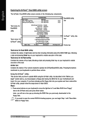
... Bios Main ROM Type/Size SST 49LF003A Backup ROM Type/Size SST 49LF003A Task menu for Dual BIOS utility Task menu for Q-FlashTM utility Enter : Run Wide Range Protection Disable Boot From Main Bios Auto Recovery Enable Halt On Error Disable Copy Main ROM Data to Backup Load Default Settings Save Settings to CMOS Q-Flash Utility Load Main BIOS from Floppy Load Backup BIOS from Floppy" item in the "Before you begin Step 1 with "Save Main BIOS to update BIOS using the Q-Flash utility. Task menu for your keyboard to enable execution of four actions needed to the floppy disk. Using...
... Bios Main ROM Type/Size SST 49LF003A Backup ROM Type/Size SST 49LF003A Task menu for Dual BIOS utility Task menu for Q-FlashTM utility Enter : Run Wide Range Protection Disable Boot From Main Bios Auto Recovery Enable Halt On Error Disable Copy Main ROM Data to Backup Load Default Settings Save Settings to CMOS Q-Flash Utility Load Main BIOS from Floppy Load Backup BIOS from Floppy" item in the "Before you begin Step 1 with "Save Main BIOS to update BIOS using the Q-Flash utility. Task menu for your keyboard to enable execution of four actions needed to the floppy disk. Using...
User Manual
Page 57
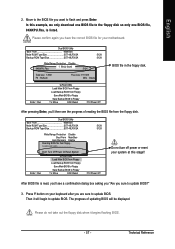
... Bios Auto Recovery Enable 512K Halt On Error Disable Total size: 1.39MCopy Main ROM Data tForeBeacskizuep: 911.50K F5 : Refresh Load Default Settings DEL : Delete Save Settings to CMOS Enter : Run Q-Flash Utility Load Main BIOS from Floppy Load Backup BIOS from Floppy Save Main BIOS to Floppy Save Backup BIOS to Floppy KL:Move ESC:Reset F10:Power Off BIOS file in the floppy disk. Dual BIOS Utility Boot From Main Bios Main ROM Type/Size SST 49LF003A Backup ROM Type/Size SST 49LF003A Wide Range Protection Disable Boot From Main Bios Auto Recovery Enable Reading...
... Bios Auto Recovery Enable 512K Halt On Error Disable Total size: 1.39MCopy Main ROM Data tForeBeacskizuep: 911.50K F5 : Refresh Load Default Settings DEL : Delete Save Settings to CMOS Enter : Run Q-Flash Utility Load Main BIOS from Floppy Load Backup BIOS from Floppy Save Main BIOS to Floppy Save Backup BIOS to Floppy KL:Move ESC:Reset F10:Power Off BIOS file in the floppy disk. Dual BIOS Utility Boot From Main Bios Main ROM Type/Size SST 49LF003A Backup ROM Type/Size SST 49LF003A Wide Range Protection Disable Boot From Main Bios Auto Recovery Enable Reading...
User Manual
Page 58
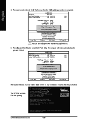
... Utility Load Main BIOS from Floppy Load Backup BIOS from Floppy Save Main BIOS to Floppy Save Backup BIOS to Floppy KL:Move ESC:Reset F10:Power Off You can repeat Step 1 to 4 to enter SETUP / Dual BIOS / Q-Flash / F9 For Xpress Recovery 09/23/2003-i875P-6A79BG03C-00 GA-K8VM800M Motherboard - 58 - The BIOS file becomes Fab after you flashed. English 4. Dual BIOS Utility Boot From Main Bios Main ROM Type/Size SST 49LF003A Backup ROM Type/Size SST 49LF003A 512K 512K Enter : Run Wide Range Protection Disable Boot From Main Bios Auto Recovery Enable Halt On Error Disable...
... Utility Load Main BIOS from Floppy Load Backup BIOS from Floppy Save Main BIOS to Floppy Save Backup BIOS to Floppy KL:Move ESC:Reset F10:Power Off You can repeat Step 1 to 4 to enter SETUP / Dual BIOS / Q-Flash / F9 For Xpress Recovery 09/23/2003-i875P-6A79BG03C-00 GA-K8VM800M Motherboard - 58 - The BIOS file becomes Fab after you flashed. English 4. Dual BIOS Utility Boot From Main Bios Main ROM Type/Size SST 49LF003A Backup ROM Type/Size SST 49LF003A 512K 512K Enter : Run Wide Range Protection Disable Boot From Main Bios Auto Recovery Enable Halt On Error Disable...
User Manual
Page 60
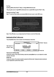
This part guides users of four actions needed to operate the Q-Flash utility. GA-K8VM800M Motherboard - 60 - CMOS Setup Utility-Copyright (C) 1984-2003 Award Software ` Standard CMOS Features Top Performance ` Advanced BIOS Features Load Fail-Safe Defaults ` Integrated Peripherals Load Optimized Defaults ` Power Management Setup Set Supervisor Password ` PnP/PCI ConfiguratEionntesr Q-Flash Utility S(Yet/NU)s?eYr Password ` PC Health Status Save & Exit Setup ` Frequency/Voltage Control Exit Without Saving ESC: Quit F8: Q-Flash KLJI: Select Item F10: Save & Exit Setup Step...
This part guides users of four actions needed to operate the Q-Flash utility. GA-K8VM800M Motherboard - 60 - CMOS Setup Utility-Copyright (C) 1984-2003 Award Software ` Standard CMOS Features Top Performance ` Advanced BIOS Features Load Fail-Safe Defaults ` Integrated Peripherals Load Optimized Defaults ` Power Management Setup Set Supervisor Password ` PnP/PCI ConfiguratEionntesr Q-Flash Utility S(Yet/NU)s?eYr Password ` PC Health Status Save & Exit Setup ` Frequency/Voltage Control Exit Without Saving ESC: Quit F8: Q-Flash KLJI: Select Item F10: Save & Exit Setup Step...
User Manual
Page 77
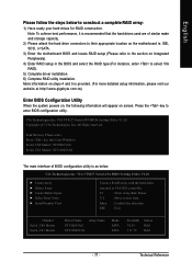
... ST9120023AS Array Name Mode SATA SATA Size(GB) 74.53 111.79 Status Hdd Hdd - 77 - VIA VT8237 Serial ATA BIOS Setting Utility V1.20 X Create Array X Delete Array X Create/Delete Spare X Select Boot Array X Serial Number View Create a RAID array with the hard disks attached to VIA IDE controller F1 : View Array/disk Status K, L : Move to select VIA RAID). 5) Complete driver installation. 6) Complete RAID utility installation. IDE, SCSI, or SATA. 3) Enter the motherboard BIOS and locate RAID setup (Please refer to...
... ST9120023AS Array Name Mode SATA SATA Size(GB) 74.53 111.79 Status Hdd Hdd - 77 - VIA VT8237 Serial ATA BIOS Setting Utility V1.20 X Create Array X Delete Array X Create/Delete Spare X Select Boot Array X Serial Number View Create a RAID array with the hard disks attached to VIA IDE controller F1 : View Array/disk Status K, L : Move to select VIA RAID). 5) Complete driver installation. 6) Complete RAID utility installation. IDE, SCSI, or SATA. 3) Enter the motherboard BIOS and locate RAID setup (Please refer to...
User Manual
Page 82
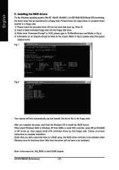
... ICH5R chipset. After that hard drive. GA-K8VM800M Motherboard - 82 - When install Windows 2000 or Windows XP from HDDs in "D:\BootDrv\menu.exe"(Refer to Fig.1) 4) Information on all chipsets should be listed on -screen instructions to complete installation. (Each time you complete the steps, boot from "Command Prompt" or DOS, please type in serial ATA controller, press F6 as Win2000 or XP boots up, then supply serial ATA controller driver by this driver file to a floppy disk. Installing the RAID drivers...
... ICH5R chipset. After that hard drive. GA-K8VM800M Motherboard - 82 - When install Windows 2000 or Windows XP from HDDs in "D:\BootDrv\menu.exe"(Refer to Fig.1) 4) Information on all chipsets should be listed on -screen instructions to complete installation. (Each time you complete the steps, boot from "Command Prompt" or DOS, please type in serial ATA controller, press F6 as Win2000 or XP boots up, then supply serial ATA controller driver by this driver file to a floppy disk. Installing the RAID drivers...

User Manual
Page 84
English Driver installation finished ! After install Windows Service Pack, it will auto-detect the right USB2.0 driver). GA-K8VM800M Motherboard - 84 - Item Description „ VIA 4IN1Driver VIA Chipset Driver „ VIA K8M800 VGA Driver VIA VGA Driver „ USB Patch for hardware change in Device Manage. Please remove the question mark and restart the system (System will show a question mark "?" For USB2.0 driver support under "Device Manager". You have to Windows XP Service Pack 1 and rescan...
English Driver installation finished ! After install Windows Service Pack, it will auto-detect the right USB2.0 driver). GA-K8VM800M Motherboard - 84 - Item Description „ VIA 4IN1Driver VIA Chipset Driver „ VIA K8M800 VGA Driver VIA VGA Driver „ USB Patch for hardware change in Device Manage. Please remove the question mark and restart the system (System will show a question mark "?" For USB2.0 driver support under "Device Manager". You have to Windows XP Service Pack 1 and rescan...

User Manual
Page 87
... a floppy disk before installing drivers. Question 3: Why cannot I still get a weak sound after updating BIOS. Answer: If your board doesn't have such jumper, you will not be able to see some rather different steps in the RAID manual at http://tw.giga-byte.com/support/user_pdf/raid_manual.pdf) Question 5: How do I clear CMOS? Press Del to MB again and turn on boards that were included in the battery holder...
... a floppy disk before installing drivers. Question 3: Why cannot I still get a weak sound after updating BIOS. Answer: If your board doesn't have such jumper, you will not be able to see some rather different steps in the RAID manual at http://tw.giga-byte.com/support/user_pdf/raid_manual.pdf) Question 5: How do I clear CMOS? Press Del to MB again and turn on boards that were included in the battery holder...
User Manual
Page 88
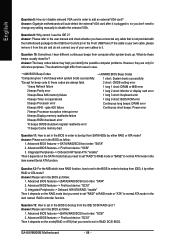
...-->(SATA)/RAID/SCSI boot order: "SCSI" 2. English Question 8: How do I disable onboard VGA card in order to bootup from SATA HDDs by either RAID or ATA mode? gate A20 failure Continuous short beeps: Power error 7 beeps Processor exception interrupt error 8 beeps Display memory read/write failure 9 beeps ROM checksum error 10 beeps CMOS shutdown register read/write error 11 beeps Cache memory bad Question 11: How to set "RAID" to RAID mode or "ATA" to normal ATA mode in the BIOS as follow : 1. Question 9: Why cannot I use the IDE 2? GA-K8VM800M Motherboard...
...-->(SATA)/RAID/SCSI boot order: "SCSI" 2. English Question 8: How do I disable onboard VGA card in order to bootup from SATA HDDs by either RAID or ATA mode? gate A20 failure Continuous short beeps: Power error 7 beeps Processor exception interrupt error 8 beeps Display memory read/write failure 9 beeps ROM checksum error 10 beeps CMOS shutdown register read/write error 11 beeps Cache memory bad Question 11: How to set "RAID" to RAID mode or "ATA" to normal ATA mode in the BIOS as follow : 1. Question 9: Why cannot I use the IDE 2? GA-K8VM800M Motherboard...


