
User Manual
Page 1
GA-K8NXP-SLI AMD Socket 939 Processor Motherboard User's Manual Rev. 1004 12ME-K8NXPSLI-1004
GA-K8NXP-SLI AMD Socket 939 Processor Motherboard User's Manual Rev. 1004 12ME-K8NXPSLI-1004

User Manual
Page 2
Motherboard GA-K8NXP-SLI Dec. 14, 2004 Motherboard GA-K8NXP-SLI Dec. 14, 2004
Motherboard GA-K8NXP-SLI Dec. 14, 2004 Motherboard GA-K8NXP-SLI Dec. 14, 2004
User Manual
Page 4
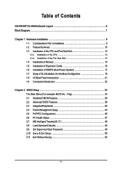
Table of Contents GA-K8NXP-SLI Motherboard Layout 6 Block Diagram ...7 Chapter 1 Hardware Installation 9 1-1 Considerations Prior to Installation 9 1-2 Feature Summary 10 1-3 Installation of the CPU and Fan Heat Sink 12 1-3-1 ... 1-3-2 Installation of the Fan Heat Sink 13 1-4 Installation of Memory 14 1-5 Installation of Expansion Cards 16 1-6 Installation of K8DPS (Dual Power System 17 1-7 Setup of SLI (Scalable Link Interface) Configuration 18 1-8 I/O Back Panel Introduction 21 1-9 Connectors Introduction 22 Chapter 2 BIOS Setup 33 The Main Menu (For example: BIOS Ver. :...
Table of Contents GA-K8NXP-SLI Motherboard Layout 6 Block Diagram ...7 Chapter 1 Hardware Installation 9 1-1 Considerations Prior to Installation 9 1-2 Feature Summary 10 1-3 Installation of the CPU and Fan Heat Sink 12 1-3-1 ... 1-3-2 Installation of the Fan Heat Sink 13 1-4 Installation of Memory 14 1-5 Installation of Expansion Cards 16 1-6 Installation of K8DPS (Dual Power System 17 1-7 Setup of SLI (Scalable Link Interface) Configuration 18 1-8 I/O Back Panel Introduction 21 1-9 Connectors Introduction 22 Chapter 2 BIOS Setup 33 The Main Menu (For example: BIOS Ver. :...
User Manual
Page 10
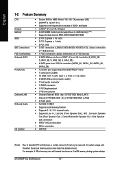
... of 4 IDE devices Š 1 FDD connection, allows connection of 2 FDD devices Š 4 SATA 3Gb/s ports from nVIDIA® nForce4 SLI controller (S_ATA0_SB, S_ATA1_SB, S_ATA2_SB, S_ATA3_SB); Š 4 SATA ports from SiI3114 controller (SATA0_SII, SATA1_SII, SATA2_SII, SATA3_SII) Š 1 parallel port... Š ALC850 CODEC Š Supports Jack Sensing function Š Supports 2 / 4 / 6 / 8 channel audio Š Supports Line In ; GA-K8NXP-SLI Motherboard - 10 - For example, 4 GB of memory size will instead be shown as 3.xxGB memory during system startup. Center/Subwoofer Speaker Out ; Line...
... of 4 IDE devices Š 1 FDD connection, allows connection of 2 FDD devices Š 4 SATA 3Gb/s ports from nVIDIA® nForce4 SLI controller (S_ATA0_SB, S_ATA1_SB, S_ATA2_SB, S_ATA3_SB); Š 4 SATA ports from SiI3114 controller (SATA0_SII, SATA1_SII, SATA2_SII, SATA3_SII) Š 1 parallel port... Š ALC850 CODEC Š Supports Jack Sensing function Š Supports 2 / 4 / 6 / 8 channel audio Š Supports Line In ; GA-K8NXP-SLI Motherboard - 10 - For example, 4 GB of memory size will instead be shown as 3.xxGB memory during system startup. Center/Subwoofer Speaker Out ; Line...
User Manual
Page 11
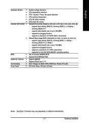
...; System voltage detection CPU temperature detection CPU / System / Power fan speed detection CPU warning temperature CPU fan failure warning CPU smart fan control Onboard nForce4 SLI chipset (S_ATA0_SB, S_ATA1_SB, S_ATA2_SB, S_ATA3_SB) -
...; System voltage detection CPU temperature detection CPU / System / Power fan speed detection CPU warning temperature CPU fan failure warning CPU smart fan control Onboard nForce4 SLI chipset (S_ATA0_SB, S_ATA1_SB, S_ATA2_SB, S_ATA3_SB) -
User Manual
Page 12
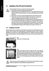
If you install the CPU in accordance with the following conditions: 1. Please use , otherwise overheating and permanent damage of the CPU may occur. 5. GA-K8NXP-SLI Motherboard - 12 - Please set the CPU host frequency in the wrong direction, the CPU will not fit if positioned incorrectly. The pin 1 location is designated ...
If you install the CPU in accordance with the following conditions: 1. Please use , otherwise overheating and permanent damage of the CPU may occur. 5. GA-K8NXP-SLI Motherboard - 12 - Please set the CPU host frequency in the wrong direction, the CPU will not fit if positioned incorrectly. The pin 1 location is designated ...
User Manual
Page 14
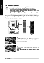
... memory capacity and specifications. Insert the DIMM memory module vertically into the DIMM socket. Please make sure that they can only fit in one direction. GA-K8NXP-SLI Motherboard - 14 - Reverse the installation steps when you are designed so that the computer power is switched off to remove the DIMM module. English 1-4 Installation...
... memory capacity and specifications. Insert the DIMM memory module vertically into the DIMM socket. Please make sure that they can only fit in one direction. GA-K8NXP-SLI Motherboard - 14 - Reverse the installation steps when you are designed so that the computer power is switched off to remove the DIMM module. English 1-4 Installation...

User Manual
Page 15
English Dual Channel Memory Configuration The GA-K8NXP-SLI supports the Dual Channel Technology. To enable Dual Channel mode with 4 memory modules, it is recommended to boot. (DS: Double Side, SS: Single Side) 1 memory ...
English Dual Channel Memory Configuration The GA-K8NXP-SLI supports the Dual Channel Technology. To enable Dual Channel mode with 4 memory modules, it is recommended to boot. (DS: Double Side, SS: Single Side) 1 memory ...
User Manual
Page 16
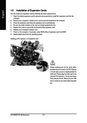
... of the expansion card. 6. Make sure your VGA card is locked by following the steps outlined below: 1. Press the expansion card firmly into the computer. 2. GA-K8NXP-SLI Motherboard - 16 - Remove your computer's chassis cover. 7. Read the related expansion card's instruction document before install the expansion card into expansion slot in the slot...
... of the expansion card. 6. Make sure your VGA card is locked by following the steps outlined below: 1. Press the expansion card firmly into the computer. 2. GA-K8NXP-SLI Motherboard - 16 - Remove your computer's chassis cover. 7. Read the related expansion card's instruction document before install the expansion card into expansion slot in the slot...
User Manual
Page 18
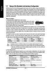
... module has gold edge connectors on the GAK8NXP-SLI motherboard. Installing a device to your overall system configurations. Understanding the GIGABYTE SLI switch module: You can be available except for different systems. GA-K8NXP-SLI Motherboard - 18 - You need to x 16 in SLI or Normal Mode before installation. The SLI design takes advantage of the increased bandwidth of it...
... module has gold edge connectors on the GAK8NXP-SLI motherboard. Installing a device to your overall system configurations. Understanding the GIGABYTE SLI switch module: You can be available except for different systems. GA-K8NXP-SLI Motherboard - 18 - You need to x 16 in SLI or Normal Mode before installation. The SLI design takes advantage of the increased bandwidth of it...
User Manual
Page 19
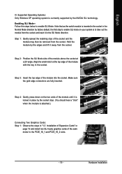
.... Align the small notch at a 25o angle. Step 3: Insert the top edge of Expansion Cards" on your system is inserted in the socket in the SLI Mode direction. English III. Step 1: Gently spread the retaining clips of the socket and the module may then be removed from the socket and insert... it in the Normal Mode direction by factory default, the first step to enable SLI mode on page 16 and install two SLI-ready graphics cards of the module until it away from the socket. Hold the module by the edges and lift it...
.... Align the small notch at a 25o angle. Step 3: Insert the top edge of Expansion Cards" on your system is inserted in the socket in the SLI Mode direction. English III. Step 1: Gently spread the retaining clips of the socket and the module may then be removed from the socket and insert... it in the Normal Mode direction by factory default, the first step to enable SLI mode on page 16 and install two SLI-ready graphics cards of the module until it away from the socket. Hold the module by the edges and lift it...

User Manual
Page 20
... Plug the display cable into either one of the two graphics cards for display output. Step 2: Select SLI multi-GPU from the side menu and then select the Enable SLI multi-GPU checkbox in your system tray and then select NVIDIA Display. Make sure the two mini female...the card on the bridge connector se- GA-K8NXP-SLI Motherboard - 20 - English Step 2: Insert the SLI bridge (the GC-SLICON) to the SLI gold edge connector on top of both cards. Then the SLI configuration is completed. System will appear. curely fit onto the SLI gold edge connetors of both cards. ...
... Plug the display cable into either one of the two graphics cards for display output. Step 2: Select SLI multi-GPU from the side menu and then select the Enable SLI multi-GPU checkbox in your system tray and then select NVIDIA Display. Make sure the two mini female...the card on the bridge connector se- GA-K8NXP-SLI Motherboard - 20 - English Step 2: Insert the SLI bridge (the GC-SLICON) to the SLI gold edge connector on top of both cards. Then the SLI configuration is completed. System will appear. curely fit onto the SLI gold edge connetors of both cards. ...

User Manual
Page 22
... configure 2-/4-/6-/8-channel audio functioning. 1-9 Connectors Introduction 13 8 11 13 1) ATX_12V 2) ATX (Power Connector) 3) CPU_FAN 4) SYS_FAN 5) PWR_FAN 6) NB_FAN 7) FDD 8) IDE1 / IDE2 9) S_ATA0/1/2/3_SB 10) SATA0/1/2/3_SII GA-K8NXP-SLI Motherboard 2 5 7 19 6 18 9 12 14 4 15 17 10 16 11) F_AUDIO 12) F_PANEL 13) CD_IN 14) PWR_LED 15) IR/CIR 16) F_USB1 / F_USB2/F_USB3 17...
... configure 2-/4-/6-/8-channel audio functioning. 1-9 Connectors Introduction 13 8 11 13 1) ATX_12V 2) ATX (Power Connector) 3) CPU_FAN 4) SYS_FAN 5) PWR_FAN 6) NB_FAN 7) FDD 8) IDE1 / IDE2 9) S_ATA0/1/2/3_SB 10) SATA0/1/2/3_SII GA-K8NXP-SLI Motherboard 2 5 7 19 6 18 9 12 14 4 15 17 10 16 11) F_AUDIO 12) F_PANEL 13) CD_IN 14) PWR_LED 15) IR/CIR 16) F_USB1 / F_USB2/F_USB3 17...

User Manual
Page 24
... connection design. Sometimes will not work. Please remember to connect the power to the CPU fan to prevent system overheating and failure. Definition 1 +12V 2 GND GA-K8NXP-SLI Motherboard - 24 - Caution! A red power connector wire indicates a positive connection and requires a +12V power voltage. The black connector wire is GND) 1 Pin No...
... connection design. Sometimes will not work. Please remember to connect the power to the CPU fan to prevent system overheating and failure. Definition 1 +12V 2 GND GA-K8NXP-SLI Motherboard - 24 - Caution! A red power connector wire indicates a positive connection and requires a +12V power voltage. The black connector wire is GND) 1 Pin No...
User Manual
Page 26
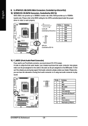
English 9) S_ATA0/1/2/3_SB (SATA 3Gb/s Connectors, Controlled by nForce4 SLI) 10) SATA0/1/2/3_SII (SATA Connectors, Controlled by Sil3114) Definition GND TXP ...must have the alternative of using front audio connector or of using rear audio connector to work properly. 7 1 S_ATA_SB (Controlled by nForce4 SLI) 7 1 Pin No. 1 2 3 4 5 6 7 SATA_SII (Controlled by Sil3114) SATA 3Gb/s can have front audio connector.... 6 7 8 9 10 Definition MIC GND MIC_BIAS Power Front Audio (R) Rear Audio (R)/ Return R NC No Pin Front Audio (L) Rear Audio (L)/ Return L GA-K8NXP-SLI Motherboard - 26 -
English 9) S_ATA0/1/2/3_SB (SATA 3Gb/s Connectors, Controlled by nForce4 SLI) 10) SATA0/1/2/3_SII (SATA Connectors, Controlled by Sil3114) Definition GND TXP ...must have the alternative of using front audio connector or of using rear audio connector to work properly. 7 1 S_ATA_SB (Controlled by nForce4 SLI) 7 1 Pin No. 1 2 3 4 5 6 7 SATA_SII (Controlled by Sil3114) SATA 3Gb/s can have front audio connector.... 6 7 8 9 10 Definition MIC GND MIC_BIAS Power Front Audio (R) Rear Audio (R)/ Return R NC No Pin Front Audio (L) Rear Audio (L)/ Return L GA-K8NXP-SLI Motherboard - 26 -
User Manual
Page 28
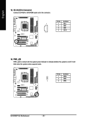
English 13) CD_IN (CD In Connector) Connect CD-ROM or DVD-ROM audio out to indicate whether the system is connect with the system power indicator to the connector. Pin No. It will blink when the system enters suspend mode. GA-K8NXP-SLI Motherboard - 28 - Pin No. Definition 1 1 CD-L 2 GND 3 GND 4 CD-R 14) PWR_LED PWR_LED is on/off. Definition 1 MPD+ 2 MPD- 1 3 MPD-
English 13) CD_IN (CD In Connector) Connect CD-ROM or DVD-ROM audio out to indicate whether the system is connect with the system power indicator to the connector. Pin No. It will blink when the system enters suspend mode. GA-K8NXP-SLI Motherboard - 28 - Pin No. Definition 1 1 CD-L 2 GND 3 GND 4 CD-R 14) PWR_LED PWR_LED is on/off. Definition 1 MPD+ 2 MPD- 1 3 MPD-
User Manual
Page 30
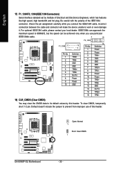
For optional IEEE1394 cable, please contact your local dealer. Open: Normal 1 Short: Clear CMOS 1 GA-K8NXP-SLI Motherboard - 30 - Check the pin assignment carefully while you use of this header. To clear CMOS, temporarily short 1-2 pin. Default doesn't include the jumper to ...
For optional IEEE1394 cable, please contact your local dealer. Open: Normal 1 Short: Clear CMOS 1 GA-K8NXP-SLI Motherboard - 30 - Check the pin assignment carefully while you use of this header. To clear CMOS, temporarily short 1-2 pin. Default doesn't include the jumper to ...
User Manual
Page 34
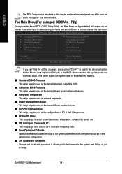
... & Exit Setup Time, Date, Hard Disk Type... If you can't find the setting you enter Award BIOS CMOS Setup Utility, the Main Menu (as usual. GA-K8NXP-SLI Motherboard - 34 - Use arrow keys to select among the items and press to Setup. CMOS Setup Utility-Copyright (C) 1984-2005 Award Software ` Standard CMOS Features...
... & Exit Setup Time, Date, Hard Disk Type... If you can't find the setting you enter Award BIOS CMOS Setup Utility, the Main Menu (as usual. GA-K8NXP-SLI Motherboard - 34 - Use arrow keys to select among the items and press to Setup. CMOS Setup Utility-Copyright (C) 1984-2005 Award Software ` Standard CMOS Features...
User Manual
Page 36
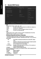
... Mode Use this if no IDE devices are : CHS/LBA/Large/Auto(default:Auto) Capacity Capacity of heads Precomp Write precomp Landing Zone Landing zone GA-K8NXP-SLI Motherboard - 36 - Enter the appropriate option based on this option for the hard drive. IDE Channel 1 Master/Slave devices setup. User can use one of...
... Mode Use this if no IDE devices are : CHS/LBA/Large/Auto(default:Auto) Capacity Capacity of heads Precomp Write precomp Landing Zone Landing zone GA-K8NXP-SLI Motherboard - 36 - Enter the appropriate option based on this option for the hard drive. IDE Channel 1 Master/Slave devices setup. User can use one of...
User Manual
Page 38
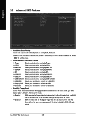
... boot device priority by ZIP. Disabled BIOS will determine the floppy disk drive installed is 40 or 80 tracks. 360K type is 360K. (Default value) GA-K8NXP-SLI Motherboard - 38 - USB-HDD Select your boot device priority by Hard Disk. Hard Disk Select your boot device priority by USB-CDROM. English 2-2 Advanced BIOS...
... boot device priority by ZIP. Disabled BIOS will determine the floppy disk drive installed is 40 or 80 tracks. 360K type is 360K. (Default value) GA-K8NXP-SLI Motherboard - 38 - USB-HDD Select your boot device priority by Hard Disk. Hard Disk Select your boot device priority by USB-CDROM. English 2-2 Advanced BIOS...


