User Manual
Page 6
English Table of Contents Read Me First 4 Chapter 1 Introduction 8 Features Summary 8 GA-K8NS Ultra-939 Motherboard Layout 10 Block Diagram 11 Chapter 2 Hardware Installation Process 13 Step 1: Install the Central Processing Unit (CPU 14 Step 2: Install Memory Modules 16 Step 3: Install Expansion Cards 18 Step 4: Install I/O Peripherals Cables 19 Step 4-1: I/O Back Panel Introduction 19 ... BIOS Features 40 Integrated Peripherals 42 Power Management Setup 46 PnP/PCI Configurations 48 PC Health Status 49 MB Intelligent Tweaker(M.I.T 50 GA-K8NS Ultra-939 Motherboard - 6 -
English Table of Contents Read Me First 4 Chapter 1 Introduction 8 Features Summary 8 GA-K8NS Ultra-939 Motherboard Layout 10 Block Diagram 11 Chapter 2 Hardware Installation Process 13 Step 1: Install the Central Processing Unit (CPU 14 Step 2: Install Memory Modules 16 Step 3: Install Expansion Cards 18 Step 4: Install I/O Peripherals Cables 19 Step 4-1: I/O Back Panel Introduction 19 ... BIOS Features 40 Integrated Peripherals 42 Power Management Setup 46 PnP/PCI Configurations 48 PC Health Status 49 MB Intelligent Tweaker(M.I.T 50 GA-K8NS Ultra-939 Motherboard - 6 -
User Manual
Page 8
... will instead be continued... (Note 1) Due to be shown as 3.xxGB memory during system startup. GA-K8NS Ultra-939 Motherboard - 8 - English Chapter 1 Introduction Features Summary CPU Chipset Memory Slots IDE Connections FDD Connections Onboard SATA Peripherals Onboard LAN y Socket 939 for AMD Althlon™ 64 / 64FX processor (K8) y 2000MHz system bus y Supports core frequencies in excess of...
... will instead be continued... (Note 1) Due to be shown as 3.xxGB memory during system startup. GA-K8NS Ultra-939 Motherboard - 8 - English Chapter 1 Introduction Features Summary CPU Chipset Memory Slots IDE Connections FDD Connections Onboard SATA Peripherals Onboard LAN y Socket 939 for AMD Althlon™ 64 / 64FX processor (K8) y 2000MHz system bus y Supports core frequencies in excess of...
User Manual
Page 13
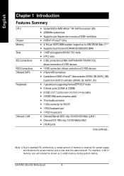
Install Expansion Cards Step 4 - Turn on the power supply or connect the power cable to the power outlet. Install Memory Modules Step 3 - Continue with the BIOS/software installation. - 13 - Install I/O Peripherals Cables Step 4 Step 1 Step 2 Step 4 Step 3 Step 4 Congratulations! Install the Central Processing Unit (CPU) Step 2 - English Chapter 2 Hardware Installation Process To set up your computer, you must complete the following steps: Step 1 - Hardware Installation Process You have accomplished the hardware installation!
Install Expansion Cards Step 4 - Turn on the power supply or connect the power cable to the power outlet. Install Memory Modules Step 3 - Continue with the BIOS/software installation. - 13 - Install I/O Peripherals Cables Step 4 Step 1 Step 2 Step 4 Step 3 Step 4 Congratulations! Install the Central Processing Unit (CPU) Step 2 - English Chapter 2 Hardware Installation Process To set up your computer, you must complete the following steps: Step 1 - Hardware Installation Process You have accomplished the hardware installation!
User Manual
Page 14
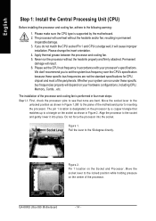
... the processor pins to see that matches up to the socket and gently lower it will depend on your hardware configurations, including CPU, Memory, Cards...etc. Align the processor to a triangle on the processor by the motherboard. 2. Pin 1 location on the center of the... pressure on the Socket and Processor. Do not force the processor into place. Never run under these specific bus frequencies are bent. GA-K8NS Ultra-939 Motherboard - 14 - Permanent damage will overheat without the heatsink properly and firmly attached. English Step 1: Install the Central Processing Unit ...
... the processor pins to see that matches up to the socket and gently lower it will depend on your hardware configurations, including CPU, Memory, Cards...etc. Align the processor to a triangle on the processor by the motherboard. 2. Pin 1 location on the center of the... pressure on the Socket and Processor. Do not force the processor into place. Never run under these specific bus frequencies are bent. GA-K8NS Ultra-939 Motherboard - 14 - Permanent damage will overheat without the heatsink properly and firmly attached. English Step 1: Install the Central Processing Unit ...
User Manual
Page 16
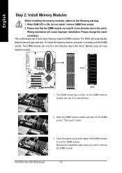
... down. 3. The DIMM module can only fit in one direction due to the notch. The DIMM socket has a notch, so the DIMM memory module can vary between sockets. GA-K8NS Ultra-939 Motherboard - 16 - Please change the insert orientation. Then push it vertically into the DIMM socket. Reverse the installation steps when you wish to...
... down. 3. The DIMM module can only fit in one direction due to the notch. The DIMM socket has a notch, so the DIMM memory module can vary between sockets. GA-K8NS Ultra-939 Motherboard - 16 - Please change the insert orientation. Then push it vertically into the DIMM socket. Reverse the installation steps when you wish to...
User Manual
Page 17
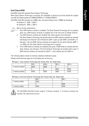
...: Single Side) DDR 1 DDR 3 1 memory module DS/SS X X DS/SS 2 memory module DS/SS DS/SS The GA-K8NS Ultra-939 doesn't support 3 memory modules. GA-K8NS Ultra-939 includes four DIMM slots, and each Channel has 2 DIMMs as Single Channel. 2. English Dual Channel DDR: GA-K8NS Ultra-939 supports Dual Channel Technology. Two DDR memory modules are installed (the same memory size and type): The Dual...
...: Single Side) DDR 1 DDR 3 1 memory module DS/SS X X DS/SS 2 memory module DS/SS DS/SS The GA-K8NS Ultra-939 doesn't support 3 memory modules. GA-K8NS Ultra-939 includes four DIMM slots, and each Channel has 2 DIMMs as Single Channel. 2. English Dual Channel DDR: GA-K8NS Ultra-939 supports Dual Channel Technology. Two DDR memory modules are installed (the same memory size and type): The Dual...

User Manual
Page 27
English 13) PWR_LED PWR_LED is connect with the system power indicator to the stand by voltage. Pin No. It might cause short or other unexpected damages due to indicate whether the system is on . Hardware Installation Process Definition 1 MPD+ 1 2 MPD- 3 MPD- 14) RAM_LED Do not remove memory modules while RAM_LED is disconnected. + _ - 27 - It will turn to another color. Remove memory modules only when AC power cord is on /off. If you use dual color LED, power LED will blink when the system enters suspend mode.
English 13) PWR_LED PWR_LED is connect with the system power indicator to the stand by voltage. Pin No. It might cause short or other unexpected damages due to indicate whether the system is on . Hardware Installation Process Definition 1 MPD+ 1 2 MPD- 3 MPD- 14) RAM_LED Do not remove memory modules while RAM_LED is disconnected. + _ - 27 - It will turn to another color. Remove memory modules only when AC power cord is on /off. If you use dual color LED, power LED will blink when the system enters suspend mode.
User Manual
Page 38
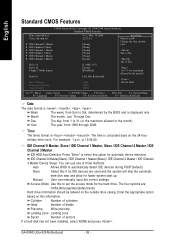
... devices are : CHS/LBA/Large/Auto(default:Auto) Hard drive information should be labeled on the 24-hour military-time clock. GA-K8NS Ultra-939 Motherboard - 38 - English Standard CMOS Features CMOS Setup Utility-Copyright (C) 1984-2004 Award Software Standard CMOS Features Date (mm:dd...Slave ` IDE Channel 1 Master ` IDE Channel 1 Slave ` IDE Channel 2 Master ` IDE Channel 3 Master Drive A Drive B Floppy 3 Mode Suport Halt On Base Memory Extended Memory Total Memory Wed, May 19 2004 22:31:24 [None] [None] [None] [None] [None] [None] [1.44M, 3.5"] [None] [Disabled] [All, But Keyboard] 640K...
... devices are : CHS/LBA/Large/Auto(default:Auto) Hard drive information should be labeled on the 24-hour military-time clock. GA-K8NS Ultra-939 Motherboard - 38 - English Standard CMOS Features CMOS Setup Utility-Copyright (C) 1984-2004 Award Software Standard CMOS Features Date (mm:dd...Slave ` IDE Channel 1 Master ` IDE Channel 1 Slave ` IDE Channel 2 Master ` IDE Channel 3 Master Drive A Drive B Floppy 3 Mode Suport Halt On Base Memory Extended Memory Total Memory Wed, May 19 2004 22:31:24 [None] [None] [None] [None] [None] [None] [1.44M, 3.5"] [None] [Disabled] [All, But Keyboard] 640K...
User Manual
Page 39
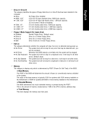
...other errors. (Default value) All, But Diskette The system boot will determine the amount of base (or conventional) memory installed in the CPU's memory address map. Total Memory This item displays the memory size that has been installed in the computer. Drive B Drive B is Enabled). 720K, 3.5" 3.5 inch double-... will not stop for all other errors. All, But Disk/Key The system boot will stop if an error is present during power up. Memory The category is display-only which is 3 mode Floppy Drive. English Drive A / Drive B The category identifies the types of floppy disk ...
...other errors. (Default value) All, But Diskette The system boot will determine the amount of base (or conventional) memory installed in the CPU's memory address map. Total Memory This item displays the memory size that has been installed in the computer. Drive B Drive B is Enabled). 720K, 3.5" 3.5 inch double-... will not stop for all other errors. All, But Disk/Key The system boot will stop if an error is present during power up. Memory The category is display-only which is 3 mode Floppy Drive. English Drive A / Drive B The category identifies the types of floppy disk ...
User Manual
Page 86
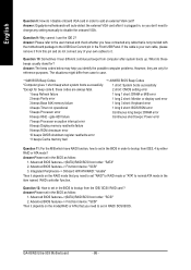
... beeps Display memory read/write failure 9 beeps ROM checksum error 10 beeps CMOS shutdown register read/write error 11 beeps Cache memory bad Question ...11: For the M/B which have connected any cable that you need to set in the BIOS as follow : 1. Answer:Please set in RAID/ SCSI BIOS. Advanced BIOS features-->(SATA)/RAID/SCSI boot order: "SCSI" 2. GA-K8NS Ultra-939...M/B error 2 beeps Parity error 1 long 2 short: Monitor or display card error 3 beeps Base 64K memory failure 1 long 3 short: Keyboard error 4 beeps Timer not operational 1 long 9 short: BIOS ROM ...
... beeps Display memory read/write failure 9 beeps ROM checksum error 10 beeps CMOS shutdown register read/write error 11 beeps Cache memory bad Question ...11: For the M/B which have connected any cable that you need to set in the BIOS as follow : 1. Answer:Please set in RAID/ SCSI BIOS. Advanced BIOS features-->(SATA)/RAID/SCSI boot order: "SCSI" 2. GA-K8NS Ultra-939...M/B error 2 beeps Parity error 1 long 2 short: Monitor or display card error 3 beeps Base 64K memory failure 1 long 3 short: Keyboard error 4 beeps Timer not operational 1 long 9 short: BIOS ROM ...
User Manual
Page 87
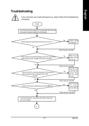
.... A - 87 - Please make sure motherboard & chassis are correct. Failure has been excluded. Insert the VGA card. Yes Check if the memory install properly into the DIMM slot. Yes Failure has been excluded. Plug the CPU cooling fan power No in the AC power connector. No Insert... and push the memory module vertically into the DIMM slot. START Turn off the power and unplug the AC power cable, then remove all jumper settings (...
.... A - 87 - Please make sure motherboard & chassis are correct. Failure has been excluded. Insert the VGA card. Yes Check if the memory install properly into the DIMM slot. Yes Failure has been excluded. Plug the CPU cooling fan power No in the AC power connector. No Insert... and push the memory module vertically into the DIMM slot. START Turn off the power and unplug the AC power cable, then remove all jumper settings (...
User Manual
Page 88
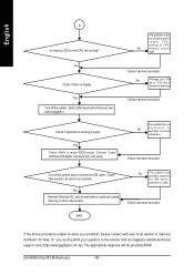
... above procedure unable to the service mail via Gigabyte website technical support zone (http://www.gigabyte.com.tw). Yes Check if there is defective. Check if keyboard is defective. No The problem was probably caused by power supply, CPU, memory or CPU/ No memory socket itself. GA-K8NS Ultra-939 Motherboard - 88 - Yes Turn off the system and...
... above procedure unable to the service mail via Gigabyte website technical support zone (http://www.gigabyte.com.tw). Yes Check if there is defective. Check if keyboard is defective. No The problem was probably caused by power supply, CPU, memory or CPU/ No memory socket itself. GA-K8NS Ultra-939 Motherboard - 88 - Yes Turn off the system and...
User Manual
Page 90
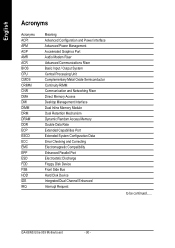
GA-K8NS Ultra-939 Motherboard - 90 - English Acronyms Acronyms ACPI APM AGP AMR ACR BIOS CPU CMOS CRIMM CNR DMA DMI DIMM DRM DRAM DDR ECP ESCD ECC EMC ... Basic Input / Output System Central Processing Unit Complementary Metal Oxide Semiconductor Continuity RIMM Communication and Networking Riser Direct Memory Access Desktop Management Interface Dual Inline Memory Module Dual Retention Mechanism Dynamic Random Access Memory Double Data Rate Extended Capabilities Port Extended System Configuration Data Error Checking and Correcting Electromagnetic Compatibility Enhanced Parallel Port...
GA-K8NS Ultra-939 Motherboard - 90 - English Acronyms Acronyms ACPI APM AGP AMR ACR BIOS CPU CMOS CRIMM CNR DMA DMI DIMM DRM DRAM DDR ECP ESCD ECC EMC ... Basic Input / Output System Central Processing Unit Complementary Metal Oxide Semiconductor Continuity RIMM Communication and Networking Riser Direct Memory Access Desktop Management Interface Dual Inline Memory Module Dual Retention Mechanism Dynamic Random Access Memory Double Data Rate Extended Capabilities Port Extended System Configuration Data Error Checking and Correcting Electromagnetic Compatibility Enhanced Parallel Port...


