
User Manual
Page 5
.... Computer motherboards and expansion cards contain very delicate Integrated Circuit (IC) chips. In this way you plug in or remove the ATX power connector on the inside. 2. To protect them against damage from static electricity, you should follow some precautions whenever you can still attach... the board or cause board malfunctioning. - 5 - Hold components by the hole. Installing the motherboard to a metal object, such as the power supply case. 3. If the motherboard has mounting holes, but they don't line up with the components whenever the components are no slots to the...
.... Computer motherboards and expansion cards contain very delicate Integrated Circuit (IC) chips. In this way you plug in or remove the ATX power connector on the inside. 2. To protect them against damage from static electricity, you should follow some precautions whenever you can still attach... the board or cause board malfunctioning. - 5 - Hold components by the hole. Installing the motherboard to a metal object, such as the power supply case. 3. If the motherboard has mounting holes, but they don't line up with the components whenever the components are no slots to the...
User Manual
Page 6
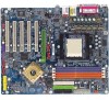
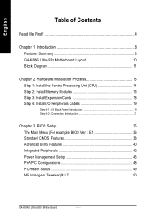
English Table of Contents Read Me First 4 Chapter 1 Introduction 8 Features Summary 8 GA-K8NS Ultra-939 Motherboard Layout 10 Block Diagram 11 Chapter 2 Hardware Installation Process 13 Step 1: Install the Central Processing Unit (CPU 14 Step 2: Install Memory Modules 16 Step 3: ... 21 Chapter 3 BIOS Setup 35 The Main Menu (For example: BIOS Ver. : E1 36 Standard CMOS Features 38 Advanced BIOS Features 40 Integrated Peripherals 42 Power Management Setup 46 PnP/PCI Configurations 48 PC Health Status 49 MB Intelligent Tweaker(M.I.T 50 GA-K8NS Ultra-939 Motherboard - 6 -
English Table of Contents Read Me First 4 Chapter 1 Introduction 8 Features Summary 8 GA-K8NS Ultra-939 Motherboard Layout 10 Block Diagram 11 Chapter 2 Hardware Installation Process 13 Step 1: Install the Central Processing Unit (CPU 14 Step 2: Install Memory Modules 16 Step 3: ... 21 Chapter 3 BIOS Setup 35 The Main Menu (For example: BIOS Ver. : E1 36 Standard CMOS Features 38 Advanced BIOS Features 40 Integrated Peripherals 42 Power Management Setup 46 PnP/PCI Configurations 48 PC Health Status 49 MB Intelligent Tweaker(M.I.T 50 GA-K8NS Ultra-939 Motherboard - 6 -
User Manual
Page 9
... Back Speaker (by optional Surround-Kit) y SPDIF In / Out y CD In / Game connector Onboard SATA RAID y Onboard nVIDIA® nForce3TM Ultra chipset (SATA0_SB, SATA1_SB) y Supports data striping (RAID 0) or mirroring (RAID 1) function y Supports data transfer rate of up 150 MB y... hot plugging function y Supports a maximum of 2 SATA connections I/O Control y IT8712 Hardware Monitor y CPU / System / Power fan speed detection y CPU / System / Power fan failure warning y CPU temperature detection y CPU warning temperature y System voltage detection y CPU smart fan control y Thermal ...
... Back Speaker (by optional Surround-Kit) y SPDIF In / Out y CD In / Game connector Onboard SATA RAID y Onboard nVIDIA® nForce3TM Ultra chipset (SATA0_SB, SATA1_SB) y Supports data striping (RAID 0) or mirroring (RAID 1) function y Supports data transfer rate of up 150 MB y... hot plugging function y Supports a maximum of 2 SATA connections I/O Control y IT8712 Hardware Monitor y CPU / System / Power fan speed detection y CPU / System / Power fan failure warning y CPU temperature detection y CPU warning temperature y System voltage detection y CPU smart fan control y Thermal ...
User Manual
Page 13
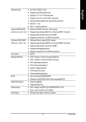
Continue with the BIOS/software installation. - 13 - Hardware Installation Process Install the Central Processing Unit (CPU) Step 2 - Install Memory Modules Step 3 - You have accomplished the hardware installation! Install I/O Peripherals Cables Step 4 Step 1 Step 2 Step 4 Step 3 Step 4 Congratulations! Install Expansion Cards Step 4 - Turn on the power supply or connect the power cable to the power outlet. English Chapter 2 Hardware Installation Process To set up your computer, you must complete the following steps: Step 1 -
Continue with the BIOS/software installation. - 13 - Hardware Installation Process Install the Central Processing Unit (CPU) Step 2 - Install Memory Modules Step 3 - You have accomplished the hardware installation! Install I/O Peripherals Cables Step 4 Step 1 Step 2 Step 4 Step 3 Step 4 Congratulations! Install Expansion Cards Step 4 - Turn on the power supply or connect the power cable to the power outlet. English Chapter 2 Hardware Installation Process To set up your computer, you must complete the following steps: Step 1 -
User Manual
Page 15
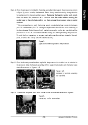
Phase change materials develop strong adhesive forces between your CPU and heatsink. (The CPU cooling fan might damage the processor. Connecting the fan power wires. - 15 - When the processor is installed in the socket, apply thermal grease to the processor(as shown in Figure 4 & 5. Align ... processor, the heatsink can cause the processor to be attached to provide better heat conduction between the heatsink and processor. Connect the fan power wires to the header on the motherboard as shown in Figure 3) prior to the processor. To avoid this condition if you try to...
Phase change materials develop strong adhesive forces between your CPU and heatsink. (The CPU cooling fan might damage the processor. Connecting the fan power wires. - 15 - When the processor is installed in the socket, apply thermal grease to the processor(as shown in Figure 4 & 5. Align ... processor, the heatsink can cause the processor to be attached to provide better heat conduction between the heatsink and processor. Connect the fan power wires to the header on the motherboard as shown in Figure 3) prior to the processor. To avoid this condition if you try to...
User Manual
Page 18
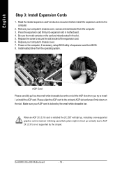
...your computer's chassis cover, screws and slot bracket from the operating system. Press the expansion card firmly into the computer. 2. Power on the card are indeed seated in motherboard. 4. AGP Card Please carefully pull out the small white-drawable bar at the ... AGP card is locked by the chipset. Be sure the metal contacts on the computer, if necessary, setup BIOS utility of the expansion card. 6. GA-K8NS Ultra-939 Motherboard - 18 - Replace the screw to install / uninstall the AGP card. English Step 3: Install Expansion Cards 1. Informing users that system might not...
...your computer's chassis cover, screws and slot bracket from the operating system. Press the expansion card firmly into the computer. 2. Power on the card are indeed seated in motherboard. 4. AGP Card Please carefully pull out the small white-drawable bar at the ... AGP card is locked by the chipset. Be sure the metal contacts on the computer, if necessary, setup BIOS utility of the expansion card. 6. GA-K8NS Ultra-939 Motherboard - 18 - Replace the screw to install / uninstall the AGP card. English Step 3: Install Expansion Cards 1. Informing users that system might not...
User Manual
Page 22
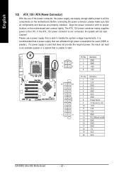
... that does not provide the required power, the result can withstand high power consumption be used (300W or greater). Align the power connector with its proper location on /off) 15 GND 16 GND 17 GND 18 -5V 19 VCC 20 VCC GA-K8NS Ultra-939 Motherboard - 22 - The ATX_12V power connector mainly supplies power to start . Definition 1 GND 3 4 2 GND...
... that does not provide the required power, the result can withstand high power consumption be used (300W or greater). Align the power connector with its proper location on /off) 15 GND 16 GND 17 GND 18 -5V 19 VCC 20 VCC GA-K8NS Ultra-939 Motherboard - 22 - The ATX_12V power connector mainly supplies power to start . Definition 1 GND 3 4 2 GND...
User Manual
Page 23
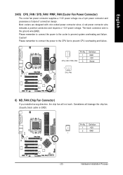
... wires. Definition 1 +12V 2 GND 1 - 23 - Please remember to connect the power to the cooler to prevent CPU overheating and failure. 1 CPU_FAN / PWR_FAN Pin No. 1 2 3 Definition GND +12V Sense 1 SYS_FAN 6) NB_FAN... remember to connect the power to the CPU fan to prevent system overheating and failure. A red power connector wire indicates a positive connection and requires a +12V power voltage. English 3/4/5) CPU_FAN / SYS_FAN / PWR_FAN (Cooler Fan Power Connector) The cooler fan power connector supplies a +12V power voltage via a 3-pin power connector and possesses a ...
... wires. Definition 1 +12V 2 GND 1 - 23 - Please remember to connect the power to the cooler to prevent CPU overheating and failure. 1 CPU_FAN / PWR_FAN Pin No. 1 2 3 Definition GND +12V Sense 1 SYS_FAN 6) NB_FAN... remember to connect the power to the CPU fan to prevent system overheating and failure. A red power connector wire indicates a positive connection and requires a +12V power voltage. English 3/4/5) CPU_FAN / SYS_FAN / PWR_FAN (Cooler Fan Power Connector) The cooler fan power connector supplies a +12V power voltage via a 3-pin power connector and possesses a ...
User Manual
Page 24
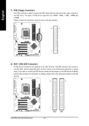
... the red power connector wire to the pin1 position. 34 33 2 1 8) IDE1 / IDE2 (IDE Connector) An IDE device connects to the FDD drive. English 7) FDD (Floppy Connector) The FDD connector is used to connect the FDD cable while the other as Slave (for information on the IDE device). 40 39 GA-K8NS Ultra-939 Motherboard...
... the red power connector wire to the pin1 position. 34 33 2 1 8) IDE1 / IDE2 (IDE Connector) An IDE device connects to the FDD drive. English 7) FDD (Floppy Connector) The FDD connector is used to connect the FDD cable while the other as Slave (for information on the IDE device). 40 39 GA-K8NS Ultra-939 Motherboard...
User Manual
Page 25
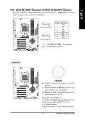
... order to the manufacturer's instructions. Replace only with the same or equivalent type recommended by the manufacturer. Turn OFF the computer and unplug the power cord. 2. Plug the power cord and turn ON the computer. - 25 - Dispose of used batteries according to work properly. 1 7 SATA0_SB / SATA1_SB 7 1 SATA0_SII / SATA1_SII Pin No. 1 2 3 4 5 6 7 Definition GND...
... order to the manufacturer's instructions. Replace only with the same or equivalent type recommended by the manufacturer. Turn OFF the computer and unplug the power cord. 2. Plug the power cord and turn ON the computer. - 25 - Dispose of used batteries according to work properly. 1 7 SATA0_SB / SATA1_SB 7 1 SATA0_SII / SATA1_SII Pin No. 1 2 3 4 5 6 7 Definition GND...

User Manual
Page 26
... 4: Data(-) Open: Normal Operation Close: Reset Hardware System Open: Normal Operation Close: Power On/Off Pin 1: LED anode(+) Pin 2: LED cathode(-) NC GA-K8NS Ultra-939 Motherboard - 26 - English 12) F_PANEL (Front Panel Jumper) Please connect the power LED, PC speaker, reset switch and power switch etc. of your chassis front panel to the F_PANEL connector according...
... 4: Data(-) Open: Normal Operation Close: Reset Hardware System Open: Normal Operation Close: Power On/Off Pin 1: LED anode(+) Pin 2: LED cathode(-) NC GA-K8NS Ultra-939 Motherboard - 26 - English 12) F_PANEL (Front Panel Jumper) Please connect the power LED, PC speaker, reset switch and power switch etc. of your chassis front panel to the F_PANEL connector according...

User Manual
Page 27
English 13) PWR_LED PWR_LED is connect with the system power indicator to indicate whether the system is on . If you use dual color LED, power LED will blink when the system enters suspend mode. It might cause short or other unexpected damages due to another color. Hardware Installation Process Pin No. Remove memory modules only when AC power cord is on /off. Definition 1 MPD+ 1 2 MPD- 3 MPD- 14) RAM_LED Do not remove memory modules while RAM_LED is disconnected. + _ - 27 - It will turn to the stand by voltage.
English 13) PWR_LED PWR_LED is connect with the system power indicator to indicate whether the system is on . If you use dual color LED, power LED will blink when the system enters suspend mode. It might cause short or other unexpected damages due to another color. Hardware Installation Process Pin No. Remove memory modules only when AC power cord is on /off. Definition 1 MPD+ 1 2 MPD- 3 MPD- 14) RAM_LED Do not remove memory modules while RAM_LED is disconnected. + _ - 27 - It will turn to the stand by voltage.

User Manual
Page 28
... connector or of using rear audio connector to play sound. 10 9 21 Pin No. 1 2 3 4 5 6 7 8 9 10 Definition MIC GND MIC_BIAS Power Front Audio (R) Rear Audio (R) Reserved No Pin Front Audio (L) Rear Audio (L) GA-K8NS Ultra-939 Motherboard - 28 - To find out if the chassis you can have front audio connector. In order to AGP 2X (3.3V...
... connector or of using rear audio connector to play sound. 10 9 21 Pin No. 1 2 3 4 5 6 7 8 9 10 Definition MIC GND MIC_BIAS Power Front Audio (R) Rear Audio (R) Reserved No Pin Front Audio (L) Rear Audio (L) GA-K8NS Ultra-939 Motherboard - 28 - To find out if the chassis you can have front audio connector. In order to AGP 2X (3.3V...
User Manual
Page 30
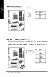
Pin No. Definition 2 10 1 Power 1 9 2 Power 3 USB Dx- 4 USB Dy- 5 USB Dx+ 6 USB Dy+ 7 GND 8 GND 9 No Pin 10 NC GA-K8NS Ultra-939 Motherboard - 30 - Check the pin assignment carefully while you connect the front USB cable, incorrect connection between the cable and connector will make the device ...
Pin No. Definition 2 10 1 Power 1 9 2 Power 3 USB Dx- 4 USB Dy- 5 USB Dx+ 6 USB Dy+ 7 GND 8 GND 9 No Pin 10 NC GA-K8NS Ultra-939 Motherboard - 30 - Check the pin assignment carefully while you connect the front USB cable, incorrect connection between the cable and connector will make the device ...

User Manual
Page 31
F1_1394 F2_1394 2 16 1 15 2 10 1 9 Pin No. 1 2 3 4 5 6 7 8 9 10 Definition TPA2+ TPA2GND GND TPB2+ TPB2No Pin Power Power GND Pin No. 1 2 3 4 5 6 7 8 9 10 11 12 13 14 15 16 Definition Power Power TPA0+ TPA0GND GND TPB0+ TPB0Power Power TPA1+ TPA1GND No Pin TPB1+ TPB1- 22) IR_CIR Make sure the pin 1 on the IR device is aling with the...
F1_1394 F2_1394 2 16 1 15 2 10 1 9 Pin No. 1 2 3 4 5 6 7 8 9 10 Definition TPA2+ TPA2GND GND TPB2+ TPB2No Pin Power Power GND Pin No. 1 2 3 4 5 6 7 8 9 10 11 12 13 14 15 16 Definition Power Power TPA0+ TPA0GND GND TPB0+ TPB0Power Power TPA1+ TPA1GND No Pin TPB1+ TPB1- 22) IR_CIR Make sure the pin 1 on the IR device is aling with the...
User Manual
Page 35
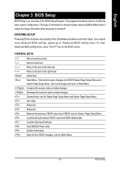
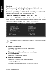
ENTERING SETUP Powering ON the computer and pressing immediately will allow you require more advanced BIOS settings, please go to enter Setup. BIOS Setup Exit current page and ... and not save changes into CMOS Status Page Setup Menu and Option Page Setup Menu - The program that it retains the Setup information when the power is stored in the right hand Select Item Main Menu -
ENTERING SETUP Powering ON the computer and pressing immediately will allow you require more advanced BIOS settings, please go to enter Setup. BIOS Setup Exit current page and ... and not save changes into CMOS Status Page Setup Menu and Option Page Setup Menu - The program that it retains the Setup information when the power is stored in the right hand Select Item Main Menu -
User Manual
Page 36
...CMOS Setup Utility-Copyright (C) 1984-2004 Award Software ` Standard CMOS Features ` Advanced BIOS Features ` Integrated Peripherals ` Power Management Setup ` PnP/PCI Configurations ` PC Health Status ` MB Intelligent Tweaker(M.I.T.) Top Performance Select Language Load Optimized Defaults... of the highlighted setup function is displayed at the bottom of Award special enhanced features. z Power Management Setup This setup page includes all the items in standard compatible BIOS. GA-K8NS Ultra-939 Motherboard - 36 - The Main Menu allows you to accept or enter the sub-menu. ...
...CMOS Setup Utility-Copyright (C) 1984-2004 Award Software ` Standard CMOS Features ` Advanced BIOS Features ` Integrated Peripherals ` Power Management Setup ` PnP/PCI Configurations ` PC Health Status ` MB Intelligent Tweaker(M.I.T.) Top Performance Select Language Load Optimized Defaults... of the highlighted setup function is displayed at the bottom of Award special enhanced features. z Power Management Setup This setup page includes all the items in standard compatible BIOS. GA-K8NS Ultra-939 Motherboard - 36 - The Main Menu allows you to accept or enter the sub-menu. ...
User Manual
Page 39
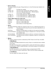
... boot will stop for a keyboard or disk error; Memory The category is display-only which is present during power up. Extended Memory The BIOS determines how much extended memory is determined by POST (Power On Self Test) of the BIOS will be prompted. it will not stop for any error that used...
... boot will stop for a keyboard or disk error; Memory The category is display-only which is present during power up. Extended Memory The BIOS determines how much extended memory is determined by POST (Power On Self Test) of the BIOS will be prompted. it will not stop for any error that used...

User Manual
Page 46
...function. (Default value) Enabled Enable alarm function to S3/STR (Suspend To RAM). Day of Month Alarm x Time (hh:mm:ss) Alarm Power On by Mouse Power On by Keyboard x KB Power ON Password AC Back Function [S1(POS)] [Instant-Off] [Disabled] [Disabled] [Disabled] [Disabled] Everyday 0 : 0 : 0 [Disabled]...-2004 Award Software Power Management Setup ACPI Suspend Type Soft-Off by PWR-BTTN PME Event Wake Up Modem Ring On S3 Resume by USB device Resume by Alarm x Day of Month Alarm : Everyday, 1~31 Time (hh: mm: ss) Alarm : (0~23) : (0~59) : (0~59) GA-K8NS Ultra-939 Motherboard - 46...
...function. (Default value) Enabled Enable alarm function to S3/STR (Suspend To RAM). Day of Month Alarm x Time (hh:mm:ss) Alarm Power On by Mouse Power On by Keyboard x KB Power ON Password AC Back Function [S1(POS)] [Instant-Off] [Disabled] [Disabled] [Disabled] [Disabled] Everyday 0 : 0 : 0 [Disabled]...-2004 Award Software Power Management Setup ACPI Suspend Type Soft-Off by PWR-BTTN PME Event Wake Up Modem Ring On S3 Resume by USB device Resume by Alarm x Day of Month Alarm : Everyday, 1~31 Time (hh: mm: ss) Alarm : (0~23) : (0~59) : (0~59) GA-K8NS Ultra-939 Motherboard - 46...
User Manual
Page 47
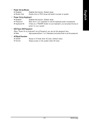
...characters) and press Enter to set the password. AC Back Function Soft-Off Always in off state when AC back. (Default value) Full-On Always power on your system. Enter Input password(from 1 to 5 characters to set the password here. Keyboard 98 If there is... a "POWER" button on your keyboard, you can press the key to power on password. Power On by Keyboard Disabled Disabled this function. (Default value) Double Click Double click on PS/2 mouse left button to power on the system when AC back. - 47 -
...characters) and press Enter to set the password. AC Back Function Soft-Off Always in off state when AC back. (Default value) Full-On Always power on your system. Enter Input password(from 1 to 5 characters to set the password here. Keyboard 98 If there is... a "POWER" button on your keyboard, you can press the key to power on password. Power On by Keyboard Disabled Disabled this function. (Default value) Double Click Double click on PS/2 mouse left button to power on the system when AC back. - 47 -


