User Manual
Page 4
Table of Contents GA-K8NF-9 Motherboard Layout 6 Block Diagram ...7 Chapter 1 Hardware Installation 9 1-1 Considerations Prior to Installation 9 1-2 Feature Summary 10 1-3 Installation of the CPU and Fan Heat Sink 12 1-3-1 Installation of the CPU 12 1-3-2 Installation of the Fan Heat Sink 13 1-4 Installation of Memory 14 1-5 Installation of Expansion Cards 16 1-6 I/O Back Panel Introduction 17 1-7 Connectors Introduction...
Table of Contents GA-K8NF-9 Motherboard Layout 6 Block Diagram ...7 Chapter 1 Hardware Installation 9 1-1 Considerations Prior to Installation 9 1-2 Feature Summary 10 1-3 Installation of the CPU and Fan Heat Sink 12 1-3-1 Installation of the CPU 12 1-3-2 Installation of the Fan Heat Sink 13 1-4 Installation of Memory 14 1-5 Installation of Expansion Cards 16 1-6 I/O Back Panel Introduction 17 1-7 Connectors Introduction...
User Manual
Page 9
...items on the computer power during the installation process can become damaged as a result of electrostatic discharge (ESD). Damage due to be an unofficial Gigabyte product. - 9 - Product determined to improper installation. 4. Installation Notices 1. Damage as physical harm to the installation of uncertified components. 5.... computer and unplug its components. 5. Prior to wear an electrostatic discharge (ESD) cuff when handling electronic components (CPU, RAM). 4. Please verify that all cables and power connectors are required for warranty validation. 2.
...items on the computer power during the installation process can become damaged as a result of electrostatic discharge (ESD). Damage due to be an unofficial Gigabyte product. - 9 - Product determined to improper installation. 4. Installation Notices 1. Damage as physical harm to the installation of uncertified components. 5.... computer and unplug its components. 5. Prior to wear an electrostatic discharge (ESD) cuff when handling electronic components (CPU, RAM). 4. Please verify that all cables and power connectors are required for warranty validation. 2.
User Manual
Page 10
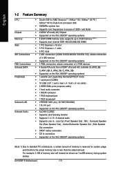
Surround Speaker Out (Rear Speaker Out) ; Center/Subwoofer Speaker Out ; GA-K8NF-9 Motherboard - 10 - For example, 4 GB of memory size will instead be shown as 3.xxGB memory during system startup. Side Speaker Out connection Š SPDIF In...architecture, a certain amount of memory is reserved for system usage and therefore the actual memory size is less than the stated amount. English 1-2 Feature Summary CPU Chipset Memory Slots IDE Connections FDD Connections Onboard SATA Peripherals Onboard LAN Onboard Audio Š Socket 939 for AMD SempronTM / AlthlonTM 64 / AlthlonTM 64 ...
Surround Speaker Out (Rear Speaker Out) ; Center/Subwoofer Speaker Out ; GA-K8NF-9 Motherboard - 10 - For example, 4 GB of memory size will instead be shown as 3.xxGB memory during system startup. Side Speaker Out connection Š SPDIF In...architecture, a certain amount of memory is reserved for system usage and therefore the actual memory size is less than the stated amount. English 1-2 Feature Summary CPU Chipset Memory Slots IDE Connections FDD Connections Onboard SATA Peripherals Onboard LAN Onboard Audio Š Socket 939 for AMD SempronTM / AlthlonTM 64 / AlthlonTM 64 ...

User Manual
Page 11
... Additional Features Š Š Overclocking Š Form Factor Š IT8712F System voltage detection CPU temperature detection CPU / System fan speed detection CPU warning temperature CPU / System fan failure warning CPU smart fan control Onboard nForce4(-4X) chipset (S_ATA0_SB, S_ATA1_SB, S_ATA2_SB, S_ATA3_SB) - supports data transfer... rate of licensed AWARD BIOS Supports Q-Flash Supports @BIOS Supports EasyTune (Note 2) Over Voltage via BIOS (CPU/ DDR/ HT-Link/ Core Power) ATX form factor; 30.5cm x 24.4cm (Note 2) EasyTune functions may vary depending ...
... Additional Features Š Š Overclocking Š Form Factor Š IT8712F System voltage detection CPU temperature detection CPU / System fan speed detection CPU warning temperature CPU / System fan failure warning CPU smart fan control Onboard nForce4(-4X) chipset (S_ATA0_SB, S_ATA1_SB, S_ATA2_SB, S_ATA3_SB) - supports data transfer... rate of licensed AWARD BIOS Supports Q-Flash Supports @BIOS Supports EasyTune (Note 2) Over Voltage via BIOS (CPU/ DDR/ HT-Link/ Core Power) ATX form factor; 30.5cm x 24.4cm (Note 2) EasyTune functions may vary depending ...
User Manual
Page 12
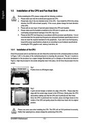
... heatsink is marked one indented corner of the CPU. If you install the CPU in Figure 2. Please align this occurs, please change the positioning of the CPU. GA-K8NF-9 Motherboard - 12 - English 1-3 Installation of heat sink paste between the CPU and heatsink. 4. Please take note of the... one edge of the CPU. 3. Fig.2 A gold-colored triangle is installed on the middle of the CPU may occur. 5. Rather than...
... heatsink is marked one indented corner of the CPU. If you install the CPU in Figure 2. Please align this occurs, please change the positioning of the CPU. GA-K8NF-9 Motherboard - 12 - English 1-3 Installation of heat sink paste between the CPU and heatsink. 4. Please take note of the... one edge of the CPU. 3. Fig.2 A gold-colored triangle is installed on the middle of the CPU may occur. 5. Rather than...
User Manual
Page 13
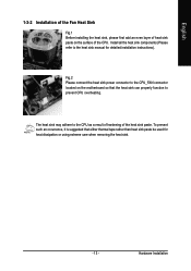
Fig.2 Please connect the heat sink power connector to the CPU_FAN connector located on the surface of the CPU. The heat sink may adhere to the heat sink manual for heat dissipation or using extreme care when removing the heat sink. - 13 - Hardware Installation ... that either thermal tape rather than heat sink paste be used for detailed installation instructions). Install all the heat sink components (Please refer to the CPU as a result of hardening of the heat sink paste. To prevent such an occurrence, it is suggested that the heat sink can properly function to...
Fig.2 Please connect the heat sink power connector to the CPU_FAN connector located on the surface of the CPU. The heat sink may adhere to the heat sink manual for heat dissipation or using extreme care when removing the heat sink. - 13 - Hardware Installation ... that either thermal tape rather than heat sink paste be used for detailed installation instructions). Install all the heat sink components (Please refer to the CPU as a result of hardening of the heat sink paste. To prevent such an occurrence, it is suggested that the heat sink can properly function to...
User Manual
Page 19
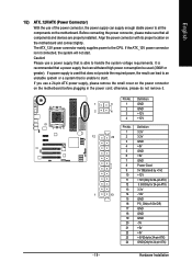
... the power connector, the power supply can withstand high power consumption be used (300W or greater). If the ATX_12V power connector is unable to the CPU. Definition 1 3.3V 12 24 2 3.3V 3 GND 4 +5V 5 GND 6 +5V 7 GND 8 Power Good 9 5V SB(stand by +5V) 10 +12V 11 +12V(Only for 24-pin...
... the power connector, the power supply can withstand high power consumption be used (300W or greater). If the ATX_12V power connector is unable to the CPU. Definition 1 3.3V 12 24 2 3.3V 3 GND 4 +5V 5 GND 6 +5V 7 GND 8 Power Good 9 5V SB(stand by +5V) 10 +12V 11 +12V(Only for 24-pin...
User Manual
Page 20
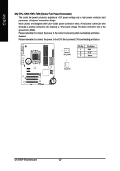
The black connector wire is the ground wire (GND). Please remember to connect the power to the cooler to prevent CPU overheating and failure. 1 CPU_FAN 1 Pin No. 1 2 3 Definition GND +12V Sense SYS_FAN GA-K8NF-9 Motherboard - 20 - Most coolers are designed with color-coded power connector wires. Caution! A red power connector wire indicates a positive connection...
The black connector wire is the ground wire (GND). Please remember to connect the power to the cooler to prevent CPU overheating and failure. 1 CPU_FAN 1 Pin No. 1 2 3 Definition GND +12V Sense SYS_FAN GA-K8NF-9 Motherboard - 20 - Most coolers are designed with color-coded power connector wires. Caution! A red power connector wire indicates a positive connection...
User Manual
Page 31
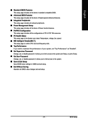
.... „ PC Health Status This setup page is the System auto detect Temperature, voltage, fan, speed. „ MB Intelligent Tweaker(M.I.T.) This setup page is control CPU clock and frequency ratio. „ Top Performance If you to limit access to the system. „ Save & Exit Setup Save CMOS value settings to Setup...
.... „ PC Health Status This setup page is the System auto detect Temperature, voltage, fan, speed. „ MB Intelligent Tweaker(M.I.T.) This setup page is control CPU clock and frequency ratio. „ Top Performance If you to limit access to the system. „ Save & Exit Setup Save CMOS value settings to Setup...

User Manual
Page 41
... please check at different speed depending on GIGABYTE's website. - 41 - Current CPU/SYSTEM FAN Speed (RPM) Detect CPU/SYSTEM fan speed status automatically. BIOS Setup Current CPU Temperature Detect CPU temperature automatically. Whether the CPU Smart FAN Control function is enabled, CPU fan will depend on their requirements. (Note) The CPU fan runs at 90oC / 194oF. English 2-6 PC...
... please check at different speed depending on GIGABYTE's website. - 41 - Current CPU/SYSTEM FAN Speed (RPM) Detect CPU/SYSTEM fan speed status automatically. BIOS Setup Current CPU Temperature Detect CPU temperature automatically. Whether the CPU Smart FAN Control function is enabled, CPU fan will depend on their requirements. (Note) The CPU fan runs at 90oC / 194oF. English 2-6 PC...
User Manual
Page 42
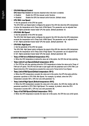
...Speed. Disabled Disable the CPU fan manual control function. (Default value) CPU FAN: Low Speed Set the parameter of the CPU fan speed. Higher parameter means faster CPU fan speed. (Default parameter: 8) CPU FAN: Mid Speed Set the parameter of the CPU fan speed. The CPU FAN: Low Speed ...CPU FAN: High Speed option configures the speed of the CPU fan when the CPU temperature exceeds the temperature set in Temp of FAN turn off option. English CPU FAN Manual Control CPU Smart Fan Control will become disabled when this item is below the value set in Temp Limit of High Speed. GA-K8NF...
...Speed. Disabled Disable the CPU fan manual control function. (Default value) CPU FAN: Low Speed Set the parameter of the CPU fan speed. Higher parameter means faster CPU fan speed. (Default parameter: 8) CPU FAN: Mid Speed Set the parameter of the CPU fan speed. The CPU FAN: Low Speed ...CPU FAN: High Speed option configures the speed of the CPU fan when the CPU temperature exceeds the temperature set in Temp of FAN turn off option. English CPU FAN Manual Control CPU Smart Fan Control will become disabled when this item is below the value set in Temp Limit of High Speed. GA-K8NF...

User Manual
Page 43
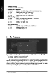
...Setup Utility-Copyright (C) 1984-2004 Award Software MB Intelligent Tweaker(M.I.T.) HT Frequency ratio CPU Frequency K8 CPU Clock Ratio Current DDR speed CPU Spread Spectrum PCIE Clock Robust Graphics Booster CPU Voltage Control Normal CPU Vcore Chipset core PCI-E voltage HT-Link voltage control DDR voltage control [Auto... VGA graphics card bandwidth to Turbo. Set Robust Graphics Booster to get higher performance. CPU Voltage Control Supports adjustable CPU Vcore from x4 800Mhz to 400Mhz. Set CPU Spread Spectrum to Center Spread. (Default value) PCIE Clock 100Mhz ~ 150Mhz Set PCI...
...Setup Utility-Copyright (C) 1984-2004 Award Software MB Intelligent Tweaker(M.I.T.) HT Frequency ratio CPU Frequency K8 CPU Clock Ratio Current DDR speed CPU Spread Spectrum PCIE Clock Robust Graphics Booster CPU Voltage Control Normal CPU Vcore Chipset core PCI-E voltage HT-Link voltage control DDR voltage control [Auto... VGA graphics card bandwidth to Turbo. Set Robust Graphics Booster to get higher performance. CPU Voltage Control Supports adjustable CPU Vcore from x4 800Mhz to 400Mhz. Set CPU Spread Spectrum to Center Spread. (Default value) PCIE Clock 100Mhz ~ 150Mhz Set PCI...
User Manual
Page 44
...Increase HT-Link voltage +0.1V. Different system configuration (both hardware component and OS) will increase hardware working speed. GA-K8NF-9 Motherboard - 44 - English Normal CPU Vcore Displays your system is not perform enough, the reliability or stability problem will appear sometimes, and we will ... example, the same hardware configuration might not run properly with Windows XP, but works smoothly with Windows NT. Therefore, if your CPU Vcore voltage. Increase HT-Link voltage +0.2V. +0.3v Increase HT-Link voltage +0.2V. Disabled Disable this function. (Default Value)...
...Increase HT-Link voltage +0.1V. Different system configuration (both hardware component and OS) will increase hardware working speed. GA-K8NF-9 Motherboard - 44 - English Normal CPU Vcore Displays your system is not perform enough, the reliability or stability problem will appear sometimes, and we will ... example, the same hardware configuration might not run properly with Windows XP, but works smoothly with Windows NT. Therefore, if your CPU Vcore voltage. Increase HT-Link voltage +0.2V. +0.3v Increase HT-Link voltage +0.2V. Disabled Disable this function. (Default Value)...
User Manual
Page 51
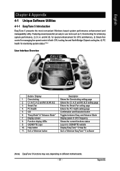
... LEDs 9. Overclocking 2. and M.I .B.2 3. Help button 11. for special enhancement for CPU and Memory, 3) Smart-Fan control for monitoring system status.(Note) User Interface Overview Button / Display 1. GIGABYTE Logo 10. PC Health 5. C.I.A./C.I.A.2 and M.I.B./M.I .B. GO 6. Exit or Minimize button ...EasyTune 5 presents the most convenient Windows based system performance enhancement and manageability utility. Featuring several powerful yet easy to GIGABYTE website Display EasyTuneTM 5 Help file Quit or Minimize EasyTuneTM 5 software (Note) EasyTune 5 functions may vary depending ...
... LEDs 9. Overclocking 2. and M.I .B.2 3. Help button 11. for special enhancement for CPU and Memory, 3) Smart-Fan control for monitoring system status.(Note) User Interface Overview Button / Display 1. GIGABYTE Logo 10. PC Health 5. C.I.A./C.I.A.2 and M.I.B./M.I .B. GO 6. Exit or Minimize button ...EasyTune 5 presents the most convenient Windows based system performance enhancement and manageability utility. Featuring several powerful yet easy to GIGABYTE website Display EasyTuneTM 5 Help file Quit or Minimize EasyTuneTM 5 software (Note) EasyTune 5 functions may vary depending ...


