
User Manual
Page 1
GA-K8N51PVMT-9-RH AMD Socket 939 Processor Motherboard User's Manual Rev. 1001 12ME-51PVMT9R-1001R * The WEEE marking on the product indicates this product must not be disposed of with user's other household waste and must be handed over to a designated collection point for the recycling of waste electrical and electronic equipment!! * The WEEE marking applies only in European Union's member states.
GA-K8N51PVMT-9-RH AMD Socket 939 Processor Motherboard User's Manual Rev. 1001 12ME-51PVMT9R-1001R * The WEEE marking on the product indicates this product must not be disposed of with user's other household waste and must be handed over to a designated collection point for the recycling of waste electrical and electronic equipment!! * The WEEE marking applies only in European Union's member states.
User Manual
Page 4
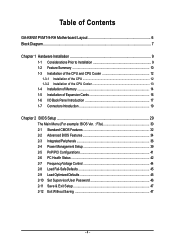
Table of Contents GA-K8N51PVMT-9-RH Motherboard Layout 6 Block Diagram ...7 Chapter 1 Hardware Installation 9 1-1 Considerations Prior to Installation 9 1-2 Feature Summary 10 1-3 Installation of the CPU and CPU Cooler 12 1-3-1 Installation of the ...
Table of Contents GA-K8N51PVMT-9-RH Motherboard Layout 6 Block Diagram ...7 Chapter 1 Hardware Installation 9 1-1 Considerations Prior to Installation 9 1-2 Feature Summary 10 1-3 Installation of the CPU and CPU Cooler 12 1-3-1 Installation of the ...
User Manual
Page 6
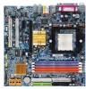
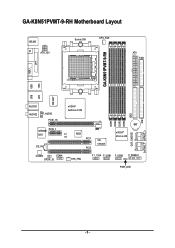
GA-K8N51PVMT-9-RH Motherboard Layout KB_MS ATX_12V Socket 939 CPU_FAN ATX FDD TV GA-K8N51PVMT-9-RH LPT VGA 1394 USB W83627 LAN USB AUDIO1 AUDIO2 F_AUDIO PCIE_16 nVIDIA® GeForce 6150 VITESSE PCIE_1 8201 CI CD_IN BIOS PCI1 PCI2 VIA VT6307 DDR1 DDR2 DDR3 DDR4 IDE2 BAT nVIDIA® nForce 430 CLR_CMOS CODEC COMA SPDIF_IO SYS_FAN F1_1394 F_USB1 F_USB2 F_PANEL1 PWR_LED IDE1 SATAII0_1 SATAII2_3 - 6 -
GA-K8N51PVMT-9-RH Motherboard Layout KB_MS ATX_12V Socket 939 CPU_FAN ATX FDD TV GA-K8N51PVMT-9-RH LPT VGA 1394 USB W83627 LAN USB AUDIO1 AUDIO2 F_AUDIO PCIE_16 nVIDIA® GeForce 6150 VITESSE PCIE_1 8201 CI CD_IN BIOS PCI1 PCI2 VIA VT6307 DDR1 DDR2 DDR3 DDR4 IDE2 BAT nVIDIA® nForce 430 CLR_CMOS CODEC COMA SPDIF_IO SYS_FAN F1_1394 F_USB1 F_USB2 F_PANEL1 PWR_LED IDE1 SATAII0_1 SATAII2_3 - 6 -
User Manual
Page 10
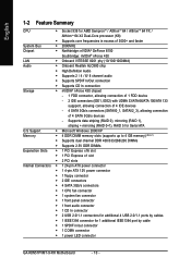
... 64 / AlthlonTM 64 FX / AlthlonTM 64 X2 Dual-Core processor (K8) Š Supports core frequencies in /out connector Š 1 COMA connector Š 1 power LED connector GA-K8N51PVMT-9-RH Motherboard - 10 - Supports data striping (RAID 0), mirroring (RAID 1), striping + mirroring (RAID 0+1), RAID 5 for Serial ATA O.S Support Š Microsoft Windows 2000/XP Memory Š 4 DDR DIMM...
... 64 / AlthlonTM 64 FX / AlthlonTM 64 X2 Dual-Core processor (K8) Š Supports core frequencies in /out connector Š 1 COMA connector Š 1 power LED connector GA-K8N51PVMT-9-RH Motherboard - 10 - Supports data striping (RAID 0), mirroring (RAID 1), striping + mirroring (RAID 0+1), RAID 5 for Serial ATA O.S Support Š Microsoft Windows 2000/XP Memory Š 4 DDR DIMM...
User Manual
Page 12
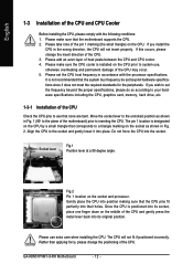
... original position. The pin 1 location is installed on the CPU prior to a triangle marking on the socket as shown in accordance with the following conditions: 1. GA-K8N51PVMT-9-RH Motherboard - 12 - It is positioned into its socket, place one finger down on the socket and processor. If you install the CPU in Fig. 2. English...
... original position. The pin 1 location is installed on the CPU prior to a triangle marking on the socket as shown in accordance with the following conditions: 1. GA-K8N51PVMT-9-RH Motherboard - 12 - It is positioned into its socket, place one finger down on the socket and processor. If you install the CPU in Fig. 2. English...
User Manual
Page 14
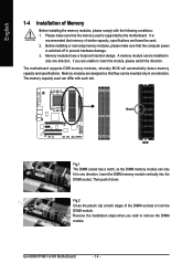
..., specifications and brand be used can only fit in one direction. Memory modules have a foolproof insertion design. The memory capacity used . 2. Then push it down. GA-K8N51PVMT-9-RH Motherboard - 14 - The motherboard supports DDR memory modules, whereby BIOS will automatically detect memory capacity and specifications. Notch DDR Fig.1 The DIMM socket has a notch...
..., specifications and brand be used can only fit in one direction. Memory modules have a foolproof insertion design. The memory capacity used . 2. Then push it down. GA-K8N51PVMT-9-RH Motherboard - 14 - The motherboard supports DDR memory modules, whereby BIOS will automatically detect memory capacity and specifications. Notch DDR Fig.1 The DIMM socket has a notch...

User Manual
Page 15
... mode will cause system unable to CPU limitation, if you must install them in DDR1 and DDR2 DIMM sockets. English Dual Channel Memory Configuration The GA-K8N51PVMT-9-RH supports the Dual Channel Technology. Due to boot. (DS: Double Side, SS: Single Side) 1 memory module 2 memory modules 3 memory modules DDR 1 X X X DS/SS X DS/SS...
... mode will cause system unable to CPU limitation, if you must install them in DDR1 and DDR2 DIMM sockets. English Dual Channel Memory Configuration The GA-K8N51PVMT-9-RH supports the Dual Channel Technology. Due to boot. (DS: Double Side, SS: Single Side) 1 memory module 2 memory modules 3 memory modules DDR 1 X X X DS/SS X DS/SS...
User Manual
Page 16
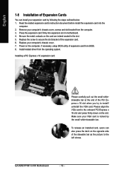
... slot and press firmly down on the slot. Make sure your expansion card by the small white-drawable bar. Install related driver from the computer. 3. GA-K8N51PVMT-9-RH Motherboard - 16 - Replace the screw to secure the slot bracket of expansion card from BIOS. 8. Read the related expansion card's instruction document before install the...
... slot and press firmly down on the slot. Make sure your expansion card by the small white-drawable bar. Install related driver from the computer. 3. GA-K8N51PVMT-9-RH Motherboard - 16 - Replace the screw to secure the slot bracket of expansion card from BIOS. 8. Read the related expansion card's instruction document before install the...
User Manual
Page 18
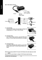
... out port or the VGA port as the vedio output port, not both together. (Note 3) You can use audio software to configure 2-/4-/6-/8-channel audio functioning. GA-K8N51PVMT-9-RH Motherboard - 18 -
... out port or the VGA port as the vedio output port, not both together. (Note 3) You can use audio software to configure 2-/4-/6-/8-channel audio functioning. GA-K8N51PVMT-9-RH Motherboard - 18 -

User Manual
Page 20
... 3.3V -12V GND PS_ON(soft On/Off) GND GND GND -5V +5V +5V +5V (Only for 24-pin ATX) GND(Only for 24-pin ATX) GA-K8N51PVMT-9-RH Motherboard - 20 - The ATX_12V power connector mainly supplies power to all components and devices are properly installed. Please use a 24-pin ATX power supply, please...
... 3.3V -12V GND PS_ON(soft On/Off) GND GND GND -5V +5V +5V +5V (Only for 24-pin ATX) GND(Only for 24-pin ATX) GA-K8N51PVMT-9-RH Motherboard - 20 - The ATX_12V power connector mainly supplies power to all components and devices are properly installed. Please use a 24-pin ATX power supply, please...

User Manual
Page 22
... on one IDE cable, and the single IDE cable can provide up to work properly. 1 7 7 1 Pin No. 1 2 3 4 5 6 7 Definition GND TXP TXN GND RXN RXP GND GA-K8N51PVMT-9-RH Motherboard - 22 - English 6) IDE1 / IDE2 (IDE Connector) An IDE device connects to two IDE devices (hard drive or optical drive).
... on one IDE cable, and the single IDE cable can provide up to work properly. 1 7 7 1 Pin No. 1 2 3 4 5 6 7 Definition GND TXP TXN GND RXN RXP GND GA-K8N51PVMT-9-RH Motherboard - 22 - English 6) IDE1 / IDE2 (IDE Connector) An IDE device connects to two IDE devices (hard drive or optical drive).

User Manual
Page 24
... HD+ HD- Pin 3: NC Pin 4: Data(-) Open: Normal Close: Reset Hardware System Open: Normal Close: Power On/Off Pin 1: LED anode(+) Pin 2: LED cathode(-) NC GA-K8N51PVMT-9-RH Motherboard - 24 - RESRES+ NC HD (IDE Hard Disk Active LED) SPEAK (Speaker Connector) RES (Reset Switch) PW (Power Switch) MSG (Message LED/Power/Sleep LED...
... HD+ HD- Pin 3: NC Pin 4: Data(-) Open: Normal Close: Reset Hardware System Open: Normal Close: Power On/Off Pin 1: LED anode(+) Pin 2: LED cathode(-) NC GA-K8N51PVMT-9-RH Motherboard - 24 - RESRES+ NC HD (IDE Hard Disk Active LED) SPEAK (Speaker Connector) RES (Reset Switch) PW (Power Switch) MSG (Message LED/Power/Sleep LED...
User Manual
Page 26
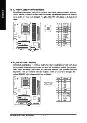
... has features like high speed, highbandwidth and hot plug. Definition 1 TPA+ 2 10 2 TPA- 1 9 3 GND 4 GND 5 TPB+ 6 TPB- 7 Power(12V) 8 Power(12V) 9 No Pin 10 GND GA-K8N51PVMT-9-RH Motherboard - 26 - Check the pin assignment carefully while you connect the IEEE1394 cable, incorrect connection between the cable and connector will make the device unable...
... has features like high speed, highbandwidth and hot plug. Definition 1 TPA+ 2 10 2 TPA- 1 9 3 GND 4 GND 5 TPB+ 6 TPB- 7 Power(12V) 8 Power(12V) 9 No Pin 10 GND GA-K8N51PVMT-9-RH Motherboard - 26 - Check the pin assignment carefully while you connect the IEEE1394 cable, incorrect connection between the cable and connector will make the device unable...

User Manual
Page 28
Default doesn't include the jumper to detect if the chassis cover is removed. To clear CMOS, temporarily short 1-2 pin. Definition 1 1 Signal 2 GND GA-K8N51PVMT-9-RH Motherboard - 28 - You can check the "Case Open" status in BIOS Setup. English 17) CLR_CMOS (Clear CMOS) You may clear the CMOS data to its default values by this header. 1 Open: Normal 1 Short: Clear CMOS 18) CI (Chassis Intrusion, Case Open) This 2-pin connector allows your system to avoid improper use of this header. Pin No.
Default doesn't include the jumper to detect if the chassis cover is removed. To clear CMOS, temporarily short 1-2 pin. Definition 1 1 Signal 2 GND GA-K8N51PVMT-9-RH Motherboard - 28 - You can check the "Case Open" status in BIOS Setup. English 17) CLR_CMOS (Clear CMOS) You may clear the CMOS data to its default values by this header. 1 Open: Normal 1 Short: Clear CMOS 18) CI (Chassis Intrusion, Case Open) This 2-pin connector allows your system to avoid improper use of this header. Pin No.
User Manual
Page 30
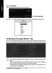
GA-K8N51PVMT-9-RH F3a . . . . :BIOS Setup/Q-Flash, : Xpress Recovery2, For Boot Menu 01/11/2006-C51-MCP51-6A61HG0CC-00 For Boot Menu Use < > or < > to select a device, then ... BIOS CMOS Setup Utility, the Main Menu (as usual. This action makes the system reset to the default for onboard (or add-on the screen. GA-K8N51PVMT-9-RH Motherboard - 30 - Please Load Optimized Defaults in this menu. CMOS Setup Utility-Copyright (C) 1984-2006 Award Software ` Standard CMOS Features ` Advanced BIOS Features ` Integrated Peripherals...
GA-K8N51PVMT-9-RH F3a . . . . :BIOS Setup/Q-Flash, : Xpress Recovery2, For Boot Menu 01/11/2006-C51-MCP51-6A61HG0CC-00 For Boot Menu Use < > or < > to select a device, then ... BIOS CMOS Setup Utility, the Main Menu (as usual. This action makes the system reset to the default for onboard (or add-on the screen. GA-K8N51PVMT-9-RH Motherboard - 30 - Please Load Optimized Defaults in this menu. CMOS Setup Utility-Copyright (C) 1984-2006 Award Software ` Standard CMOS Features ` Advanced BIOS Features ` Integrated Peripherals...

User Manual
Page 32
...] [None] [None] [None] [None] [None] [None] [None] Change the day, month, year Sun. Jan. The day, from 1 to Sat. IDE Channel 1 Master/Slave devices setup. GA-K8N51PVMT-9-RH Motherboard - 32 - to 31 (or the maximum allowed in the month) Year The year, from Sun to 2098 KLJI: Move Enter: Select F5: Previous Values...
...] [None] [None] [None] [None] [None] [None] [None] Change the day, month, year Sun. Jan. The day, from 1 to Sat. IDE Channel 1 Master/Slave devices setup. GA-K8N51PVMT-9-RH Motherboard - 32 - to 31 (or the maximum allowed in the month) Year The year, from Sun to 2098 KLJI: Move Enter: Select F5: Previous Values...

User Manual
Page 34
... 1.44M are all 80 tracks. Disabled BIOS will determine the floppy disk drive installed is 40 or 80 tracks. 360K type is 360K. (Default value) GA-K8N51PVMT-9-RH Motherboard - 34 - CDROM Select your boot device priority by USB-FDD. Boot Up Floppy Seek During POST, BIOS will not search for onboard(or add...
... 1.44M are all 80 tracks. Disabled BIOS will determine the floppy disk drive installed is 40 or 80 tracks. 360K type is 360K. (Default value) GA-K8N51PVMT-9-RH Motherboard - 34 - CDROM Select your boot device priority by USB-FDD. Boot Up Floppy Seek During POST, BIOS will not search for onboard(or add...

User Manual
Page 36
Disabled Disable this function. (Default value) SATA-II 1 Secondary RAID Enabled Enable SATAII 1 2nd SATA RAID function. Disabled Disable this function. (Default value) GA-K8N51PVMT-9-RH Motherboard - 36 - Disabled Disable SATAII RAID function. (Default value) SATA-II 1 Primary RAID Enabled Enable SATAII 1 1st SATA RAID function. English 2-3 Integrated Peripherals CMOS Setup ...
Disabled Disable this function. (Default value) SATA-II 1 Secondary RAID Enabled Enable SATAII 1 2nd SATA RAID function. Disabled Disable this function. (Default value) GA-K8N51PVMT-9-RH Motherboard - 36 - Disabled Disable SATAII RAID function. (Default value) SATA-II 1 Primary RAID Enabled Enable SATAII 1 1st SATA RAID function. English 2-3 Integrated Peripherals CMOS Setup ...

User Manual
Page 38
.... Enabled Enable this function. (Default value) Onboard 1394 Function Enabled Enable onboard IEEE1394 function.(Default value) Disabled Disable onboard IEEE1394 function. Disable onboard Serial port 1. GA-K8N51PVMT-9-RH Motherboard - 38 - Onboard LAN Function Auto Auto-detect onboard LAN chip function.(Default value) Disabled Disable onboard LAN chip function. ECP Using Parallel port as...
.... Enabled Enable this function. (Default value) Onboard 1394 Function Enabled Enable onboard IEEE1394 function.(Default value) Disabled Disable onboard IEEE1394 function. Disable onboard Serial port 1. GA-K8N51PVMT-9-RH Motherboard - 38 - Onboard LAN Function Auto Auto-detect onboard LAN chip function.(Default value) Disabled Disable onboard LAN chip function. ECP Using Parallel port as...

User Manual
Page 40
... the password here. Any KEY Press any keys on your keyboard have "POWER Key" button, you can press the key to power on the system. GA-K8N51PVMT-9-RH Motherboard - 40 - Full-On (Default value) When AC-power back to the Last state before AC-power off. Memory When AC-power back to power...
... the password here. Any KEY Press any keys on your keyboard have "POWER Key" button, you can press the key to power on the system. GA-K8N51PVMT-9-RH Motherboard - 40 - Full-On (Default value) When AC-power back to the Last state before AC-power off. Memory When AC-power back to power...


