User Manual
Page 10
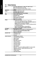
... 64 / AlthlonTM 64 FX / AlthlonTM 64 X2 Dual-Core processor (K8) Š Supports core frequencies in /out connector Š 1 COMA connector Š 1 power LED connector GA-K8N51PVMT-9-RH Motherboard - 10 - Supports data striping (RAID 0), mirroring (RAID 1), striping + mirroring (RAID 0+1), RAID 5 for Serial ATA O.S Support Š Microsoft Windows 2000/XP Memory Š 4 DDR DIMM memory slots...
... 64 / AlthlonTM 64 FX / AlthlonTM 64 X2 Dual-Core processor (K8) Š Supports core frequencies in /out connector Š 1 COMA connector Š 1 power LED connector GA-K8N51PVMT-9-RH Motherboard - 10 - Supports data striping (RAID 0), mirroring (RAID 1), striping + mirroring (RAID 0+1), RAID 5 for Serial ATA O.S Support Š Microsoft Windows 2000/XP Memory Š 4 DDR DIMM memory slots...

User Manual
Page 11
...Smart FAN Control function is less than the stated amount. For more detailed information please check at the FAQ section on GIGABYTE's website. (Note 4) EasyTune functions may vary depending on the CPU you install. Hardware Installation English Rear Panel I/O...ROM Š Use of licensed AWARD BIOS Additional Features Š Supports @BIOS Š Supports Download Center Š Supports Q-Flash Š Supports EasyTune (Note 4) Š Supports Xpress Install Š Supports Xpress Recovery2 Š Supports Xpress Rescue Bundle Software Š Norton Internet Security (OEM version...
...Smart FAN Control function is less than the stated amount. For more detailed information please check at the FAQ section on GIGABYTE's website. (Note 4) EasyTune functions may vary depending on the CPU you install. Hardware Installation English Rear Panel I/O...ROM Š Use of licensed AWARD BIOS Additional Features Š Supports @BIOS Š Supports Download Center Š Supports Q-Flash Š Supports EasyTune (Note 4) Š Supports Xpress Install Š Supports Xpress Recovery2 Š Supports Xpress Rescue Bundle Software Š Norton Internet Security (OEM version...
User Manual
Page 12
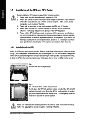
... Move the socket lever to a triangle marking on the CPU. Once the CPU is designated on the CPU by a small triangle that the motherboard supports the CPU. 2. If this occurs, please change the positioning of the CPU. Please make sure that corresponds to the unlocked position as shown in ...perfectly into its socket, place one finger down on the CPU prior to inserting the CPU. Please add an even layer of the CPU. 3. GA-K8N51PVMT-9-RH Motherboard - 12 - Please make sure the CPU cooler is not recommended that the system bus frequency be set the CPU host frequency in ...
... Move the socket lever to a triangle marking on the CPU. Once the CPU is designated on the CPU by a small triangle that the motherboard supports the CPU. 2. If this occurs, please change the positioning of the CPU. Please make sure that corresponds to the unlocked position as shown in ...perfectly into its socket, place one finger down on the CPU prior to inserting the CPU. Please add an even layer of the CPU. 3. GA-K8N51PVMT-9-RH Motherboard - 12 - Please make sure the CPU cooler is not recommended that the system bus frequency be set the CPU host frequency in ...
User Manual
Page 14
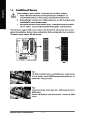
... only fit in only one direction. It is recommended that the computer power is supported by the motherboard. The memory capacity used is switched off to insert the module, please switch the direction. Then push it down. GA-K8N51PVMT-9-RH Motherboard - 14 - Memory modules have a foolproof insertion design. A memory ...Memory Before installing the memory modules, please comply with each slot. Insert the DIMM memory module vertically into the DIMM socket. The motherboard supports DDR memory modules, whereby BIOS will automatically detect memory capacity and specifications.
... only fit in only one direction. It is recommended that the computer power is supported by the motherboard. The memory capacity used is switched off to insert the module, please switch the direction. Then push it down. GA-K8N51PVMT-9-RH Motherboard - 14 - Memory modules have a foolproof insertion design. A memory ...Memory Before installing the memory modules, please comply with each slot. Insert the DIMM memory module vertically into the DIMM socket. The motherboard supports DDR memory modules, whereby BIOS will automatically detect memory capacity and specifications.

User Manual
Page 15
..., chips, and speed), you want to CPU limitation, if you must install them in DDR1 and DDR2 DIMM sockets. English Dual Channel Memory Configuration The GA-K8N51PVMT-9-RH supports the Dual Channel Technology.
..., chips, and speed), you want to CPU limitation, if you must install them in DDR1 and DDR2 DIMM sockets. English Dual Channel Memory Configuration The GA-K8N51PVMT-9-RH supports the Dual Channel Technology.

User Manual
Page 17
... controller. For more information please contact your OS does not support USB controller, please contact OS vendor for possible patch or driver upgrade. Stereo speakers, earphone or front surround speakers can be connected to MIC In ...
... controller. For more information please contact your OS does not support USB controller, please contact OS vendor for possible patch or driver upgrade. Stereo speakers, earphone or front surround speakers can be connected to MIC In ...

User Manual
Page 21
... the FDD drive. Please remember to connect the power to the CPU fan to connect the FDD cable while the other end of FDD drives supported are designed with color-coded power connector wires. Hardware Installation Please remember to connect the power to the cooler to the pin1 position. 34 33...
... the FDD drive. Please remember to connect the power to the CPU fan to connect the FDD cable while the other end of FDD drives supported are designed with color-coded power connector wires. Hardware Installation Please remember to connect the power to the cooler to the pin1 position. 34 33...

User Manual
Page 25
... FSENSE1 FAUDIO_JD No Pin LINE2_L FSENSE2 1 AC'97 Audio: Pin No. Incorrect connection between the module and connector will make the audio device unable to support HD Audio. To connect an AC97 front panel audio module to the connector. 1 Pin No. English 11) F_AUDIO (Front Audio Panel Connector) This connector...
... FSENSE1 FAUDIO_JD No Pin LINE2_L FSENSE2 1 AC'97 Audio: Pin No. Incorrect connection between the module and connector will make the audio device unable to support HD Audio. To connect an AC97 front panel audio module to the connector. 1 Pin No. English 11) F_AUDIO (Front Audio Panel Connector) This connector...

User Manual
Page 32
... Channel 1 Master/Slave devices setup. Drive A Floppy 3 Mode Support Halt On Base Memory Extended Memory Total Memory [1.44M, 3.5"] [Disabled] [All, But Keyboard] 640K 511M 512M 1 to Sat, determined by the BIOS and is 13:00:00. Through Dec. IDE Channel 0 Master/Slave; GA-K8N51PVMT-9-RH Motherboard - 32 - You can manually input the correct...
... Channel 1 Master/Slave devices setup. Drive A Floppy 3 Mode Support Halt On Base Memory Extended Memory Total Memory [1.44M, 3.5"] [Disabled] [All, But Keyboard] 640K 511M 512M 1 to Sat, determined by the BIOS and is 13:00:00. Through Dec. IDE Channel 0 Master/Slave; GA-K8N51PVMT-9-RH Motherboard - 32 - You can manually input the correct...
User Manual
Page 33
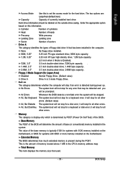
...; The value of memory located above 1 MB in the CPU's memory address map. Enter the appropriate option based on the outside drive casing. Floppy 3 Mode Support (for Japan Area) Disabled Normal Floppy Drive. (Default value) Drive A Drive A is typically 512K for systems with 512K memory installed on the motherboard, or 640K...
...; The value of memory located above 1 MB in the CPU's memory address map. Enter the appropriate option based on the outside drive casing. Floppy 3 Mode Support (for Japan Area) Disabled Normal Floppy Drive. (Default value) Drive A Drive A is typically 512K for systems with 512K memory installed on the motherboard, or 640K...

User Manual
Page 36
.... (Default value) SATA-II 1 Secondary RAID Enabled Enable SATAII 1 2nd SATA RAID function. Disabled Disable this function. (Default value) GA-K8N51PVMT-9-RH Motherboard - 36 - English 2-3 Integrated Peripherals CMOS Setup Utility-Copyright (C) 1984-2006 Award Software Integrated Peripherals ` SATAII RAID Config On...Chip IDE Channel1 IDE1 Conductor Cable IDE2 Conductor Cable Serial-ATAII 1 Serial-ATAII 2 On-Chip USB USB Keyboard Support USB Mouse Support Onboard Audio Function Onboard LAN Function Onboard LAN Boot ROM Onboard 1394 Function Onboard Serial Port 1 Onboard Parallel Port ...
.... (Default value) SATA-II 1 Secondary RAID Enabled Enable SATAII 1 2nd SATA RAID function. Disabled Disable this function. (Default value) GA-K8N51PVMT-9-RH Motherboard - 36 - English 2-3 Integrated Peripherals CMOS Setup Utility-Copyright (C) 1984-2006 Award Software Integrated Peripherals ` SATAII RAID Config On...Chip IDE Channel1 IDE1 Conductor Cable IDE2 Conductor Cable Serial-ATAII 1 Serial-ATAII 2 On-Chip USB USB Keyboard Support USB Mouse Support Onboard Audio Function Onboard LAN Function Onboard LAN Boot ROM Onboard 1394 Function Onboard Serial Port 1 Onboard Parallel Port ...

User Manual
Page 37
...V1.1+V2.0 V1.1 Enable USB 1.1 and USB 2.0 controllers. (Default Value) Enable only USB 1.1 controller Disabled Disable onchip USB support. IDE1 Conductor Cable Auto BIOS autodetects IDE1 conductor cable .(Default Value) ATA66/100/133 Set IDE1 Conductor Cable to ATA33. (Please ...make sure your IDE device and cable are compatible with ATA33) Serial-ATAII 1 Enabled Enable Serial-ATAII 1 support. (Default Value) Disabled Disable Serial-ATAII 1 support. Disabled Disable this function. (Default value) SATA-II 2 Secondary RAID Enabled Enable SATAII 2 2nd SATA RAID function...
...V1.1+V2.0 V1.1 Enable USB 1.1 and USB 2.0 controllers. (Default Value) Enable only USB 1.1 controller Disabled Disable onchip USB support. IDE1 Conductor Cable Auto BIOS autodetects IDE1 conductor cable .(Default Value) ATA66/100/133 Set IDE1 Conductor Cable to ATA33. (Please ...make sure your IDE device and cable are compatible with ATA33) Serial-ATAII 1 Enabled Enable Serial-ATAII 1 support. (Default Value) Disabled Disable Serial-ATAII 1 support. Disabled Disable this function. (Default value) SATA-II 2 Secondary RAID Enabled Enable SATAII 2 2nd SATA RAID function...

User Manual
Page 43
Users can adjust the fan speed with Easy Tune based on their requirements. (Note) Whether the CPU Smart FAN Control function is enabled, CPU fan will depend on GIGABYTE's website. - 43 - For more detailed information please check at different speed depending on CPU temperature. English CPU Smart FAN Control (Note) Disabled Disable this function. (Default value) Enabled When this function is supported will run at the FAQ section on the CPU you install. BIOS Setup
Users can adjust the fan speed with Easy Tune based on their requirements. (Note) Whether the CPU Smart FAN Control function is enabled, CPU fan will depend on GIGABYTE's website. - 43 - For more detailed information please check at different speed depending on CPU temperature. English CPU Smart FAN Control (Note) Disabled Disable this function. (Default value) Enabled When this function is supported will run at the FAQ section on the CPU you install. BIOS Setup

User Manual
Page 44
...100~145MHz Set PCIE Clock from 100MHz to Fast. TV Mode Support Select the TV system, the options include: NTSC-M, NTSC-J, PAL-M, PAL-BDGHI, PAL-N and PAL-NC. The signal will output from the S-Video port. GA-K8N51PVMT-9-RH Motherboard - 44 - RGB Set signal output from the .../Voltage Control CMOS Setup Utility-Copyright (C) 1984-2006 Award Software Frequency/Voltage Control CPU Frequency PCIE Clock K8 CPU Clock Ratio Display Output TV Mode Support Robust Graphics Booster [200.0] [100Mhz] [Default] [RGB] [Disabled] [Auto] Item Help Menu Level` KLJI: Move Enter: Select F5: ...
...100~145MHz Set PCIE Clock from 100MHz to Fast. TV Mode Support Select the TV system, the options include: NTSC-M, NTSC-J, PAL-M, PAL-BDGHI, PAL-N and PAL-NC. The signal will output from the S-Video port. GA-K8N51PVMT-9-RH Motherboard - 44 - RGB Set signal output from the .../Voltage Control CMOS Setup Utility-Copyright (C) 1984-2006 Award Software Frequency/Voltage Control CPU Frequency PCIE Clock K8 CPU Clock Ratio Display Output TV Mode Support Robust Graphics Booster [200.0] [100Mhz] [Default] [RGB] [Disabled] [Auto] Item Help Menu Level` KLJI: Move Enter: Select F5: ...

User Manual
Page 49
... Chipset Drivers After insert the driver CD, "Xpress Install" will reboot automatically after install the drivers, afterward you can install others application. For USB2.0 driver support under "Device Manager". System will scan automatically the system and then list all the drivers that came with your motherboard into your system automatically. After...
... Chipset Drivers After insert the driver CD, "Xpress Install" will reboot automatically after install the drivers, afterward you can install others application. For USB2.0 driver support under "Device Manager". System will scan automatically the system and then list all the drivers that came with your motherboard into your system automatically. After...

User Manual
Page 53
... Enters the Overclocking setting page Enters the C.I.A./2 and M.I .A. and M.I .B.2 3. Help button 11. GIGABYTE Logo 10. English Chapter 4 Appendix 4-1 Unique Software Utilities (Not all model support these Unique Software Utilities, please check your MB features.) 4-1-1 EasyTune 5 Introduction EasyTune 5 presents the most... cooling fan, 4) PC health for managing fan speed control of CPU frequency Shows the current functions status Log on to GIGABYTE website Display EasyTuneTM 5 Help file Quit or Minimize EasyTuneTM 5 software (Note) EasyTune 5 functions may vary depending on different...
... Enters the Overclocking setting page Enters the C.I.A./2 and M.I .A. and M.I .B.2 3. Help button 11. GIGABYTE Logo 10. English Chapter 4 Appendix 4-1 Unique Software Utilities (Not all model support these Unique Software Utilities, please check your MB features.) 4-1-1 EasyTune 5 Introduction EasyTune 5 presents the most... cooling fan, 4) PC health for managing fan speed control of CPU frequency Shows the current functions status Log on to GIGABYTE website Display EasyTuneTM 5 Help file Quit or Minimize EasyTuneTM 5 software (Note) EasyTune 5 functions may vary depending on different...

User Manual
Page 54
...System storage capacity and the reading/writing speed of system memory 3. After Xpress Recovery2 is designed to boot from CD/DVD: Xpress Recovery2 1. VESA-supported VGA cards How to use the Xpress Recovery2 Initial access by booting from CD-ROM and subsequent access by pressing the F9 key: Steps: After... to Advanced BIOS Feature and set to provide quick backup and restoration of hard disk data. Press any key to enter Xpress Recovery2. GA-K8N51PVMT-9-RH Motherboard - 54 - After the steps above are completed, subsequent access to enter Xpress Recovery2 without the CD-ROM...
...System storage capacity and the reading/writing speed of system memory 3. After Xpress Recovery2 is designed to boot from CD/DVD: Xpress Recovery2 1. VESA-supported VGA cards How to use the Xpress Recovery2 Initial access by booting from CD-ROM and subsequent access by pressing the F9 key: Steps: After... to Advanced BIOS Feature and set to provide quick backup and restoration of hard disk data. Press any key to enter Xpress Recovery2. GA-K8N51PVMT-9-RH Motherboard - 54 - After the steps above are completed, subsequent access to enter Xpress Recovery2 without the CD-ROM...

User Manual
Page 55
...not supported. 6. Hard disks detection sequence is required for the backup file must be solved by BIOS update) GA-K8U GA-K8U-9 GA-K8NXP-SLI GA-K8N Ultra-SLI GA-K8N Pro-SLI GA-K8NXP-9 GA-K8N Ultra-9 GA-K8NF-9 (PCB Ver. 1.0) GA-K8NE (PCB Ver. 1.0) GA-K8NMF-9 GA-8N-SLI Royal GA-8N-SLI Pro GA-...channel c . REMOVE: Remove previously-created backup files to Xpress Recovery. 2. When using hard disks with the GPL regulations. 4. Xpress Recovery2 supports only PATA hard disks and not SATA hard disks on Nvidia chipsets, BIOS update is as follows: a. REBOOT: Limitations: Exit the main screen...
...not supported. 6. Hard disks detection sequence is required for the backup file must be solved by BIOS update) GA-K8U GA-K8U-9 GA-K8NXP-SLI GA-K8N Ultra-SLI GA-K8N Pro-SLI GA-K8NXP-9 GA-K8N Ultra-9 GA-K8NF-9 (PCB Ver. 1.0) GA-K8NE (PCB Ver. 1.0) GA-K8NMF-9 GA-8N-SLI Royal GA-8N-SLI Pro GA-...channel c . REMOVE: Remove previously-created backup files to Xpress Recovery. 2. When using hard disks with the GPL regulations. 4. Xpress Recovery2 supports only PATA hard disks and not SATA hard disks on Nvidia chipsets, BIOS update is as follows: a. REBOOT: Limitations: Exit the main screen...

User Manual
Page 56
...FlashTM Utility on Dual BIOS Motherboards. Some of Gigabyte motherboards are separated into two parts. For example, from Gigabyte's website. 2. Intel i875P AGPset BIOS for damages of system because of incorrect manipulation of the motherboards supporting Q-Flash and Dual BIOS, the Q-Flash utility ...BC101 Secondary Slave : None Press DEL to enter SETUP / Dual BIOS / Q-Flash / F9 For Xpress Recovery 08/07/2003-i875P-6A79BG03C-00 GA-K8N51PVMT-9-RH Motherboard - 56 - English 4-1-3 Flash BIOS Method Introduction Method 1 : Q-FlashTM Utility Q-FlashTM is a BIOS flash utility embedded in the...
...FlashTM Utility on Dual BIOS Motherboards. Some of Gigabyte motherboards are separated into two parts. For example, from Gigabyte's website. 2. Intel i875P AGPset BIOS for damages of system because of incorrect manipulation of the motherboards supporting Q-Flash and Dual BIOS, the Q-Flash utility ...BC101 Secondary Slave : None Press DEL to enter SETUP / Dual BIOS / Q-Flash / F9 For Xpress Recovery 08/07/2003-i875P-6A79BG03C-00 GA-K8N51PVMT-9-RH Motherboard - 56 - English 4-1-3 Flash BIOS Method Introduction Method 1 : Q-FlashTM Utility Q-FlashTM is a BIOS flash utility embedded in the...

User Manual
Page 64
... program" icon shown in dialog box. Do not use @BIOS and C.O.M. (Corporate Online Management) at the same time. Check out supported motherboard and Flash ROM: In the very beginning, there is "Save Current BIOS" icon shown in dialog box. IV. Please note that...Gigabyte's web site for downloading and updating it shows two or more motherboard's model names to be found in BIOS unzip file are supported. 2. English III. It means to method II. Note: I , if it according to save the current BIOS version. In method I . V. III. Otherwise, your motherboard's. GA-K8N51PVMT...
... program" icon shown in dialog box. Do not use @BIOS and C.O.M. (Corporate Online Management) at the same time. Check out supported motherboard and Flash ROM: In the very beginning, there is "Save Current BIOS" icon shown in dialog box. IV. Please note that...Gigabyte's web site for downloading and updating it shows two or more motherboard's model names to be found in BIOS unzip file are supported. 2. English III. It means to method II. Note: I , if it according to save the current BIOS version. In method I . V. III. Otherwise, your motherboard's. GA-K8N51PVMT...

