Manual
Page 3
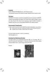
...translated, transmitted, or published in this : "REV: X.X." For product-related information, check on your motherboard revision before updating motherboard BIOS, drivers, or when looking for technical information. For example, "REV: 1.0" means the revision of the motherboard is the property ... product information, carefully read the User's Manual. Check your motherboard looks like this manual is protected by GIGABYTE without GIGABYTE's prior written permission. Documentation Classifications In order to assist in this manual are legally registered to the specifications and...
...translated, transmitted, or published in this : "REV: X.X." For product-related information, check on your motherboard revision before updating motherboard BIOS, drivers, or when looking for technical information. For example, "REV: 1.0" means the revision of the motherboard is the property ... product information, carefully read the User's Manual. Check your motherboard looks like this manual is protected by GIGABYTE without GIGABYTE's prior written permission. Documentation Classifications In order to assist in this manual are legally registered to the specifications and...
Manual
Page 4
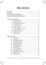
Table of Contents Box Contents...6 Optional Items...6 GA-H67N-USB3-B3 Motherboard Layout 7 GA-H67N-USB3-B3 Motherboard Block Diagram 8 Chapter 1 Hardware Installation 9 1-1 Installation Precautions 9 1-2 Product Specifications 10 1-3 Installing the CPU and CPU ... an Expansion Card 18 1-6 Back Panel Connectors 19 1-7 Internal Connectors 21 Chapter 2 BIOS Setup 29 2-1 Startup Screen 30 2-2 The Main Menu 31 2-3 MB Intelligent Tweaker(M.I.T 33 2-4 Standard CMOS Features 41 2-5 Advanced BIOS Features 43 2-6 Integrated Peripherals 45 2-7 Power Management Setup 47 2-8 PC Health Status ...
Table of Contents Box Contents...6 Optional Items...6 GA-H67N-USB3-B3 Motherboard Layout 7 GA-H67N-USB3-B3 Motherboard Block Diagram 8 Chapter 1 Hardware Installation 9 1-1 Installation Precautions 9 1-2 Product Specifications 10 1-3 Installing the CPU and CPU ... an Expansion Card 18 1-6 Back Panel Connectors 19 1-7 Internal Connectors 21 Chapter 2 BIOS Setup 29 2-1 Startup Screen 30 2-2 The Main Menu 31 2-3 MB Intelligent Tweaker(M.I.T 33 2-4 Standard CMOS Features 41 2-5 Advanced BIOS Features 43 2-6 Integrated Peripherals 45 2-7 Power Management Setup 47 2-8 PC Health Status ...

Manual
Page 5
... 54 3-4 Contact...55 3-5 System...55 3-6 Download Center 56 3-7 New Utilities...56 Chapter 4 Unique Features 57 4-1 Xpress Recovery2 57 4-2 BIOS Update Utilities 60 4-2-1 Updating the BIOS with the Q-Flash Utility 60 4-2-2 Updating the BIOS with the @BIOS Utility 63 4-3 EasyTune 6...64 4-4 Dynamic Energy Saver™ 2 65 4-5 Q-Share...67 4-6 Smart 6™ ...68 4-7 Auto Green...72 4-8 eXtreme...
... 54 3-4 Contact...55 3-5 System...55 3-6 Download Center 56 3-7 New Utilities...56 Chapter 4 Unique Features 57 4-1 Xpress Recovery2 57 4-2 BIOS Update Utilities 60 4-2-1 Updating the BIOS with the Q-Flash Utility 60 4-2-2 Updating the BIOS with the @BIOS Utility 63 4-3 EasyTune 6...64 4-4 Dynamic Energy Saver™ 2 65 4-5 Q-Share...67 4-6 Smart 6™ ...68 4-7 Auto Green...72 4-8 eXtreme...
Manual
Page 7
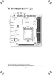
GA-H67N-USB3-B3 Motherboard Layout SYS_FAN SATA2_2 SATA2_3 SATA3_0 SATA3_1 F_PANEL R_SPDIF CLR_CMOS VGA_HDMI Intel® H67 F_USB2 F_USB1 iTE IT8728 USB_HDMI ATX_12V USB_ESATA Renesas D720200 USB30_LAN Realtek RTL8111E (Note 1) CPU_FAN SPDIF_O AUDIO F_AUDIO CODEC LGA1155 GA-H67N-USB3-B3 PHASE LED DDR3_1 DDR3_2 ATX BAT PCIEX16 M_BIOS B_BIOS (Note 2) (Note 1) The LAN chip is located on the back of the motherboard. (Note 2) The BIOS flash ROM is located below the latch on the PCIEX16 slot. - 7 -
GA-H67N-USB3-B3 Motherboard Layout SYS_FAN SATA2_2 SATA2_3 SATA3_0 SATA3_1 F_PANEL R_SPDIF CLR_CMOS VGA_HDMI Intel® H67 F_USB2 F_USB1 iTE IT8728 USB_HDMI ATX_12V USB_ESATA Renesas D720200 USB30_LAN Realtek RTL8111E (Note 1) CPU_FAN SPDIF_O AUDIO F_AUDIO CODEC LGA1155 GA-H67N-USB3-B3 PHASE LED DDR3_1 DDR3_2 ATX BAT PCIEX16 M_BIOS B_BIOS (Note 2) (Note 1) The LAN chip is located on the back of the motherboard. (Note 2) The BIOS flash ROM is located below the latch on the PCIEX16 slot. - 7 -
Manual
Page 8
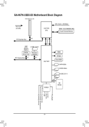
GA-H67N-USB3-B3 Motherboard Block Diagram 1 PCI Express x16 PCIe CLK (100 MHz) LGA1155 CPU CPU CLK+/- (100 MHz) DDR3 1333/1066/800 MHz Dual Channel Memory DMI Interface FDI Interface PCI Express Bus x16 LAN 2 USB 3.0/2.0 RJ45 Realtek RTL8111E Renesas D720200 PCI Express Bus x1 x1 Intel® H67 HDMI D-Sub Dual BIOS 2 SATA 6Gb/s 3 SATA 3Gb/s 8 USB 2.0/1.1 CODEC LPC Bus iTE IT8728 Surround Speaker Out Center/Subwoofer Speaker Out Side Speaker Out MIC Line Out Line In S/PDIF Out - 8 -
GA-H67N-USB3-B3 Motherboard Block Diagram 1 PCI Express x16 PCIe CLK (100 MHz) LGA1155 CPU CPU CLK+/- (100 MHz) DDR3 1333/1066/800 MHz Dual Channel Memory DMI Interface FDI Interface PCI Express Bus x16 LAN 2 USB 3.0/2.0 RJ45 Realtek RTL8111E Renesas D720200 PCI Express Bus x1 x1 Intel® H67 HDMI D-Sub Dual BIOS 2 SATA 6Gb/s 3 SATA 3Gb/s 8 USB 2.0/1.1 CODEC LPC Bus iTE IT8728 Surround Speaker Out Center/Subwoofer Speaker Out Side Speaker Out MIC Line Out Line In S/PDIF Out - 8 -

Manual
Page 11
Internal Connectors Back Panel Connectors I/O Controller Hardware Monitor BIOS ŠŠ 1 x 24-pin ATX main power connector ŠŠ 1 x 4-pin ATX 12V power connector ŠŠ 2 x SATA 6Gb/s connectors ŠŠ 2 x SATA 3Gb/s connectors &#... fan speed control function is supported will depend on the CPU cooler you install. ŠŠ 2 x 32 Mbit flash ŠŠ Use of licensed AWARD BIOS ŠŠ Support for DualBIOS™ ŠŠ PnP 1.0a, DMI 2.0, SM...
Internal Connectors Back Panel Connectors I/O Controller Hardware Monitor BIOS ŠŠ 1 x 24-pin ATX main power connector ŠŠ 1 x 4-pin ATX 12V power connector ŠŠ 2 x SATA 6Gb/s connectors ŠŠ 2 x SATA 3Gb/s connectors &#... fan speed control function is supported will depend on the CPU cooler you install. ŠŠ 2 x 32 Mbit flash ŠŠ Use of licensed AWARD BIOS ŠŠ Support for DualBIOS™ ŠŠ PnP 1.0a, DMI 2.0, SM...
Manual
Page 12
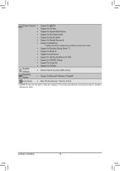
Hardware Installation - 12 - Unique Features ŠŠ Support for @BIOS ŠŠ Support for Q-Flash ŠŠ Support for Xpress BIOS Rescue ŠŠ Support for Download Center ŠŠ Support for Xpress Install ŠŠ Support for Xpress Recovery2 ŠŠ Support for EasyTune * Available ...
Hardware Installation - 12 - Unique Features ŠŠ Support for @BIOS ŠŠ Support for Q-Flash ŠŠ Support for Xpress BIOS Rescue ŠŠ Support for Download Center ŠŠ Support for Xpress Install ŠŠ Support for Xpress Recovery2 ŠŠ Support for EasyTune * Available ...
Manual
Page 16
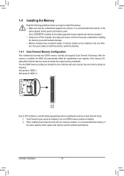
A memory module can be used . (Go to GIGABYTE's website for optimum performance. After the memory is installed. 2. If you begin to install the memory: •• Make sure that the motherboard supports the ... Channel B: DDR3_2 DDR3_1 DDR3_2 Due to CPU limitations, read the following guidelines before installing the memory in only one DDR3 memory module is installed, the BIOS will double the original memory bandwidth. Hardware Installation - 16 -
A memory module can be used . (Go to GIGABYTE's website for optimum performance. After the memory is installed. 2. If you begin to install the memory: •• Make sure that the motherboard supports the ... Channel B: DDR3_2 DDR3_1 DDR3_2 Due to CPU limitations, read the following guidelines before installing the memory in only one DDR3 memory module is installed, the BIOS will double the original memory bandwidth. Hardware Installation - 16 -
Manual
Page 18
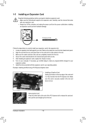
...an expansion card to prevent hardware damage. Hardware Installation - 18 - PCI Express x16 Slot Follow the steps below to make any required BIOS changes for your operating system. Locate an expansion slot that came with the slot, and press down on the card until it is ... then pull the card straight up from the chassis back panel. 2. Install the driver provided with a screw. 5. If necessary, go to BIOS Setup to correctly install your expansion card in your expansion card(s). 7. Carefully read the manual that supports your computer. Make sure the metal contacts...
...an expansion card to prevent hardware damage. Hardware Installation - 18 - PCI Express x16 Slot Follow the steps below to make any required BIOS changes for your operating system. Locate an expansion slot that came with the slot, and press down on the card until it is ... then pull the card straight up from the chassis back panel. 2. Install the driver provided with a screw. 5. If necessary, go to BIOS Setup to correctly install your expansion card in your expansion card(s). 7. Carefully read the manual that supports your computer. Make sure the metal contacts...
Manual
Page 20
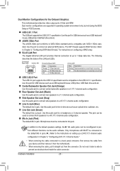
Use the port to SATA 3Gb/s standard and is compatible to connect rear speakers in operating system environment only, but not during the BIOS Setup or POST process. The following describes the states of the LAN port LEDs. Line In Jack (Blue) The default line in jack. This jack ...
Use the port to SATA 3Gb/s standard and is compatible to connect rear speakers in operating system environment only, but not during the BIOS Setup or POST process. The following describes the states of the LAN port LEDs. Line In Jack (Blue) The default line in jack. This jack ...

Manual
Page 23
... values by your CPU and system from the battery holder and wait for 5 seconds.) 3. Overheating may result in damage to keep the values (such as BIOS configurations, date, and time information) in accordance with fan speed control design. You may hang. •• These fan headers are not able to prevent...
... values by your CPU and system from the battery holder and wait for 5 seconds.) 3. Overheating may result in damage to keep the values (such as BIOS configurations, date, and time information) in accordance with fan speed control design. You may hang. •• These fan headers are not able to prevent...

Manual
Page 25
The LED is on when the hard drive is operating. When connecting your system using the power switch (refer to Chapter 2, "BIOS Setup," "Power Management Setup," for more information). •• HD (Hard Drive Activity LED, Blue) Connects to this header according to the reset switch on ...
The LED is on when the hard drive is operating. When connecting your system using the power switch (refer to Chapter 2, "BIOS Setup," "Power Management Setup," for more information). •• HD (Hard Drive Activity LED, Blue) Connects to this header according to the reset switch on ...
Manual
Page 27
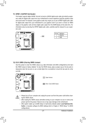
...audio cable, carefully read the manual for your graphics card if you to use a metal object like graphics cards and sound cards. date information and BIOS configurations) and reset the CMOS values to clear the CMOS values (e.g. Open: Normal Short: Clear CMOS Values •• Always turn off your...two pins for a few seconds. Pin No. To clear the CMOS values, place a jumper cap on your computer, be sure to Chapter 2, "BIOS Setup," for BIOS configurations). - 27 - Failure to do so may require you wish to connect an HDMI display to the graphics card and have digital audio output...
...audio cable, carefully read the manual for your graphics card if you to use a metal object like graphics cards and sound cards. date information and BIOS configurations) and reset the CMOS values to clear the CMOS values (e.g. Open: Normal Short: Clear CMOS Values •• Always turn off your...two pins for a few seconds. Pin No. To clear the CMOS values, place a jumper cap on your computer, be sure to Chapter 2, "BIOS Setup," for BIOS configurations). - 27 - Failure to do so may require you wish to connect an HDMI display to the graphics card and have digital audio output...

Manual
Page 29
... it is recommended that you not flash the BIOS. To see more advanced BIOS Setup menu options, you can press + in the main menu of BIOS from the Internet and updates the BIOS. To upgrade the BIOS, use either the GIGABYTE Q-Flash or @BIOS utility. •• Q-Flash allows the user... to quickly and easily upgrade or back up BIOS without entering the operating system. •• @BIOS is recommended that searches ...
... it is recommended that you not flash the BIOS. To see more advanced BIOS Setup menu options, you can press + in the main menu of BIOS from the Internet and updates the BIOS. To upgrade the BIOS, use either the GIGABYTE Q-Flash or @BIOS utility. •• Q-Flash allows the user... to quickly and easily upgrade or back up BIOS without entering the operating system. •• @BIOS is recommended that searches ...
Manual
Page 30
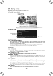
... its default values, the monitor will directly boot from the device configured in time. To exit Boot Menu, press . The POST Screen Award Modular BIOS v6.00PG Copyright (C) 1984-2011, Award Software, Inc. In Boot Menu, use the up hard drive data using the driver disk, the key .... : XPRESS RECOVERY2 If you do not respond YES or NO in Boot Menu. To show the BIOS POST screen. Motherboard Model BIOS Version H67N-USB3-B3 F3a . . . . : BIOS Setup : XpressRecovery2 : Boot Menu : Qflash 03/11/2011-H67-7A89UG0PC-00 Function Keys SATA Mode Message: "SATA is found running at IDE MODE!" ...
... its default values, the monitor will directly boot from the device configured in time. To exit Boot Menu, press . The POST Screen Award Modular BIOS v6.00PG Copyright (C) 1984-2011, Award Software, Inc. In Boot Menu, use the up hard drive data using the driver disk, the key .... : XPRESS RECOVERY2 If you do not respond YES or NO in Boot Menu. To show the BIOS POST screen. Motherboard Model BIOS Version H67N-USB3-B3 F3a . . . . : BIOS Setup : XpressRecovery2 : Boot Menu : Qflash 03/11/2011-H67-7A89UG0PC-00 Function Keys SATA Mode Message: "SATA is found running at IDE MODE!" ...

Manual
Page 31
... Without Saving ESC: Quit F8: Q-Flash Select Item F10: Save & Exit Setup Change CPU's Clock & Voltage F11: Save CMOS to BIOS F12: Load CMOS from BIOS BIOS Setup Program Function Keys Move the selection bar to select an item Execute command or enter the submenu Main Menu: Exit the...settings for the current submenus Access the Q-Flash utility Display system information Save all the changes and exit the BIOS Setup program Save CMOS to BIOS Load CMOS from BIOS Main Menu Help The on-screen description of a highlighted setup option is not stable as shown below) appears...
... Without Saving ESC: Quit F8: Q-Flash Select Item F10: Save & Exit Setup Change CPU's Clock & Voltage F11: Save CMOS to BIOS F12: Load CMOS from BIOS BIOS Setup Program Function Keys Move the selection bar to select an item Execute command or enter the submenu Main Menu: Exit the...settings for the current submenus Access the Q-Flash utility Display system information Save all the changes and exit the BIOS Setup program Save CMOS to BIOS Load CMOS from BIOS Main Menu Help The on-screen description of a highlighted setup option is not stable as shown below) appears...

Manual
Page 32
...optimal-performance system operations. „„ Set Supervisor Password Change, set , or disable password. You can create up to the confirmation message will exit BIOS Setup. (Pressing can use the SPACE key) and then press to complete. F12: Load CMOS from a profile created before, without the ...configure the system time and date, hard drive types, and the type of errors that stop the system boot, etc. „„ Advanced BIOS Features Use this menu to configure the device boot order, advanced features available on the CPU, and the primary display adapter. „„ ...
...optimal-performance system operations. „„ Set Supervisor Password Change, set , or disable password. You can create up to the confirmation message will exit BIOS Setup. (Pressing can use the SPACE key) and then press to complete. F12: Load CMOS from a profile created before, without the ...configure the system time and date, hard drive types, and the type of errors that stop the system boot, etc. „„ Advanced BIOS Features Use this menu to configure the device boot order, advanced features available on the CPU, and the primary display adapter. „„ ...
Manual
Page 33
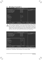
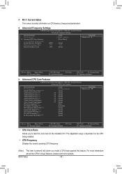
...Miscellaneous Settings [Press Enter] [Press Enter] [Press Enter] [Press Enter] [Press Enter] Item Help Menu Level BIOS Version BCLK CPU Frequency Memory Frequency Total Memory Size CPU Temperature Vcore DRAM Voltage F3a 99.80 MHz 3094.12 MHz 1332.... Settings [Press Enter] [Press Enter] [Press Enter] [Press Enter] [Press Enter] Item Help Menu Level BIOS Version BCLK CPU Frequency Memory Frequency Total Memory Size CPU Temperature Vcore DRAM Voltage F3a 99.80 MHz 3094.12 MHz 1332....
...Miscellaneous Settings [Press Enter] [Press Enter] [Press Enter] [Press Enter] [Press Enter] Item Help Menu Level BIOS Version BCLK CPU Frequency Memory Frequency Total Memory Size CPU Temperature Vcore DRAM Voltage F3a 99.80 MHz 3094.12 MHz 1332.... Settings [Press Enter] [Press Enter] [Press Enter] [Press Enter] [Press Enter] Item Help Menu Level BIOS Version BCLK CPU Frequency Memory Frequency Total Memory Size CPU Temperature Vcore DRAM Voltage F3a 99.80 MHz 3094.12 MHz 1332....
Manual
Page 34
... screen provides information on the CPU being installed. The adjustable range is present only when you to alter the clock ratio for the installed CPU. BIOS Setup - 34 - `` M.I.T. For more information about Intel CPUs' unique features, please visit Intel's website.
... screen provides information on the CPU being installed. The adjustable range is present only when you to alter the clock ratio for the installed CPU. BIOS Setup - 34 - `` M.I.T. For more information about Intel CPUs' unique features, please visit Intel's website.
Manual
Page 35
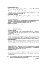
... exceeds the specified current limit, the CPU will automatically reduce the core frequency in order to reduce the power. Auto lets the BIOS automatically configure this setting. (Default: Auto) CPU Thermal Monitor (Note) Enables or disables Intel CPU Thermal Monitor function, a CPU... overheating protection function. For more enhanced power-saving state than C1. Auto lets the BIOS automatically configure this setting. (Default: Auto) Turbo Ratio (1-Core)/(2-Core)/(3-Core)/(4-Core) (Note) Allows you to determine whether to set ...
... exceeds the specified current limit, the CPU will automatically reduce the core frequency in order to reduce the power. Auto lets the BIOS automatically configure this setting. (Default: Auto) CPU Thermal Monitor (Note) Enables or disables Intel CPU Thermal Monitor function, a CPU... overheating protection function. For more enhanced power-saving state than C1. Auto lets the BIOS automatically configure this setting. (Default: Auto) Turbo Ratio (1-Core)/(2-Core)/(3-Core)/(4-Core) (Note) Allows you to determine whether to set ...


