
Manual
Page 1
GA-H67M-D2 LGA1155 socket motherboard for Intel® Core™ i7 processors/ Intel® Core™ i5 processors/Intel® Core™ i3 processors/ Intel® Pentium® processors/Intel® Celeron® processors User's Manual Rev. 1002 12ME-H67MD2-1002R
GA-H67M-D2 LGA1155 socket motherboard for Intel® Core™ i7 processors/ Intel® Core™ i5 processors/Intel® Core™ i3 processors/ Intel® Pentium® processors/Intel® Celeron® processors User's Manual Rev. 1002 12ME-H67MD2-1002R

Manual
Page 2
Motherboard GA-H67M-D2 Oct. 20, 2010 Motherboard GA-H67M-D2 Oct. 20, 2010
Motherboard GA-H67M-D2 Oct. 20, 2010 Motherboard GA-H67M-D2 Oct. 20, 2010
Manual
Page 3
... For quick set-up of the motherboard is 1.0. For product-related information, check on our website at: http://www.gigabyte.com Identifying Your Motherboard Revision The revision number on your motherboard revision before updating motherboard BIOS, drivers, or when looking for technical information...registered to the specifications and features in the use of this manual is the property of GIGABYTE. Check your motherboard looks like this manual may be made by GIGABYTE without GIGABYTE's prior written permission. Copyright © 2010 GIGA-BYTE TECHNOLOGY CO., LTD. All ...
... For quick set-up of the motherboard is 1.0. For product-related information, check on our website at: http://www.gigabyte.com Identifying Your Motherboard Revision The revision number on your motherboard revision before updating motherboard BIOS, drivers, or when looking for technical information...registered to the specifications and features in the use of this manual is the property of GIGABYTE. Check your motherboard looks like this manual may be made by GIGABYTE without GIGABYTE's prior written permission. Copyright © 2010 GIGA-BYTE TECHNOLOGY CO., LTD. All ...

Manual
Page 4
Table of Contents Box Contents...6 Optional Items...6 GA-H67M-D2 Motherboard Layout 7 GA-H67M-D2 Motherboard Block Diagram 8 Chapter 1 Hardware Installation 9 1-1 Installation Precautions 9 1-2 Product Specifications 10 1-3 Installing the CPU and CPU Cooler 13 1-3-1 Installing the CPU 13 1-3-2 Installing the CPU Cooler ...
Table of Contents Box Contents...6 Optional Items...6 GA-H67M-D2 Motherboard Layout 7 GA-H67M-D2 Motherboard Block Diagram 8 Chapter 1 Hardware Installation 9 1-1 Installation Precautions 9 1-2 Product Specifications 10 1-3 Installing the CPU and CPU Cooler 13 1-3-1 Installing the CPU 13 1-3-2 Installing the CPU Cooler ...

Manual
Page 6
The box contents are for reference only. Optional Items 2-port USB 2.0 bracket (Part No. 12CR1-1UB030-5*R) 2-port SATA power cable (Part No. 12CF1-2SERPW-0*R) COM port cable (Part No. 12CF1-1CM001-3*R) - 6 - Box Contents GA-H67M-D2 motherboard Motherboard driver disk User's Manual Quick Installation Guide Two SATA cables I/O Shield • The box contents above are subject to change without notice. • The motherboard image is for reference only and the actual items shall depend on the product package you obtain.
The box contents are for reference only. Optional Items 2-port USB 2.0 bracket (Part No. 12CR1-1UB030-5*R) 2-port SATA power cable (Part No. 12CF1-2SERPW-0*R) COM port cable (Part No. 12CF1-1CM001-3*R) - 6 - Box Contents GA-H67M-D2 motherboard Motherboard driver disk User's Manual Quick Installation Guide Two SATA cables I/O Shield • The box contents above are subject to change without notice. • The motherboard image is for reference only and the actual items shall depend on the product package you obtain.

Manual
Page 7
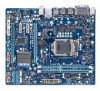
GA-H67M-D2 Motherboard Layout KB_MS ATX_12V Level Shifter LGA1155 DVI VGA DDR3_1 DDR3_2 R_USB_2 R_USB_1 ATX USB30_20 USB_LAN AUDIO GA-H67M-D2 PCIEX16 BAT CPU_FAN B_BIOS M_BIOS Realtek RTL8111E PCIEX1_1 PCIEX1_2 SYS_FAN CODEC PCIEX4 iTE IT8728 Intel® H67 CLR_CMOS SATA3_0 SATA3_1 SATA2_2 SATA2_3 SATA2_4 SATA2_5 F_AUDIO COMA COMB F_USB3 F_USB2 F_USB1 F_PANEL - 7 -
GA-H67M-D2 Motherboard Layout KB_MS ATX_12V Level Shifter LGA1155 DVI VGA DDR3_1 DDR3_2 R_USB_2 R_USB_1 ATX USB30_20 USB_LAN AUDIO GA-H67M-D2 PCIEX16 BAT CPU_FAN B_BIOS M_BIOS Realtek RTL8111E PCIEX1_1 PCIEX1_2 SYS_FAN CODEC PCIEX4 iTE IT8728 Intel® H67 CLR_CMOS SATA3_0 SATA3_1 SATA2_2 SATA2_3 SATA2_4 SATA2_5 F_AUDIO COMA COMB F_USB3 F_USB2 F_USB1 F_PANEL - 7 -

Manual
Page 8
GA-H67M-D2 Motherboard Block Diagram PCIe CLK (100 MHz) CPU CLK+/- (100 MHz) 1 PCI Express x16 LGA1155 CPU DDR3 1333/1066/800 MHz Dual Channel Memory PCI Express Bus x16 DMI Interface FDI Interface PCIe CLK (100 MHz) 1 PCI Express x4 2 PCI Express x1 x4 PCI Express Bus x1 x1 Realtek RTL8111E RJ45 LAN Intel® H67 DVI D-Sub Dual BIOS 4 SATA 3Gb/s 2 SATA 6Gb/s 14 USB 2.0/1.1 CODEC LPC Bus iTE IT8728 COM Ports PS/2 KB/Mouse MIC Line Out Line In - 8 -
GA-H67M-D2 Motherboard Block Diagram PCIe CLK (100 MHz) CPU CLK+/- (100 MHz) 1 PCI Express x16 LGA1155 CPU DDR3 1333/1066/800 MHz Dual Channel Memory PCI Express Bus x16 DMI Interface FDI Interface PCIe CLK (100 MHz) 1 PCI Express x4 2 PCI Express x1 x4 PCI Express Bus x1 x1 Realtek RTL8111E RJ45 LAN Intel® H67 DVI D-Sub Dual BIOS 4 SATA 3Gb/s 2 SATA 6Gb/s 14 USB 2.0/1.1 CODEC LPC Bus iTE IT8728 COM Ports PS/2 KB/Mouse MIC Line Out Line In - 8 -
Manual
Page 9
... please verify that all cables and power connectors of your dealer. If you are connected tightly and securely. • When handling the motherboard, avoid touching any installation steps or have it on top of an antistatic pad or within the computer casing. • Do not ... computer system on an uneven surface. • Do not place the computer system in a high-temperature environment. • Turning on the motherboard, make sure the power supply voltage has been set according to wear an electrostatic discharge (ESD) wrist strap when handling electronic com- Hardware Installation...
... please verify that all cables and power connectors of your dealer. If you are connected tightly and securely. • When handling the motherboard, avoid touching any installation steps or have it on top of an antistatic pad or within the computer casing. • Do not ... computer system on an uneven surface. • Do not place the computer system in a high-temperature environment. • Turning on the motherboard, make sure the power supply voltage has been set according to wear an electrostatic discharge (ESD) wrist strap when handling electronic com- Hardware Installation...

Manual
Page 12
... Charge Support for Cloud OC Support for Q-Share Norton Internet Security (OEM version) Operating System w Support for EasyTune * Available functions in EasyTune may differ by motherboard model. Hardware Installation - 12 - Unique Features w w w w w w w w w w w w w Bundled Software w Support for @BIOS Support for...174; 7/Vista/XP Form Factor w Micro ATX Form Factor; 24.4cm x 21.0cm * GIGABYTE reserves the right to make any changes to the product specifications and product-related information without prior notice.
... Charge Support for Cloud OC Support for Q-Share Norton Internet Security (OEM version) Operating System w Support for EasyTune * Available functions in EasyTune may differ by motherboard model. Hardware Installation - 12 - Unique Features w w w w w w w w w w w w w Bundled Software w Support for @BIOS Support for...174; 7/Vista/XP Form Factor w Micro ATX Form Factor; 24.4cm x 21.0cm * GIGABYTE reserves the right to make any changes to the product specifications and product-related information without prior notice.

Manual
Page 13
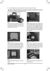
...Alignment Key Pin One Corner of the CPU. Hardware Installation It is not installed, otherwise overheating and dam- Locate the alignment keys on the motherboard CPU socket and the notches on the CPU - 13 - The CPU cannot be set the frequency beyond hardware specifications since it does not...requirements for the latest CPU support list.) • Always turn on the computer if the CPU cooler is not recommended that the motherboard supports the CPU. (Go to GIGABYTE's website for the peripherals. If you begin to install the CPU: • Make sure that the system bus frequency be ...
...Alignment Key Pin One Corner of the CPU. Hardware Installation It is not installed, otherwise overheating and dam- Locate the alignment keys on the motherboard CPU socket and the notches on the CPU - 13 - The CPU cannot be set the frequency beyond hardware specifications since it does not...requirements for the latest CPU support list.) • Always turn on the computer if the CPU cooler is not recommended that the motherboard supports the CPU. (Go to GIGABYTE's website for the peripherals. If you begin to install the CPU: • Make sure that the system bus frequency be ...
Manual
Page 14
... lever by the handle, not the lever base portion. Follow the steps below to the CPU. Step 5: Push the CPU socket lever back into the motherboard CPU socket.
... lever by the handle, not the lever base portion. Follow the steps below to the CPU. Step 5: Push the CPU socket lever back into the motherboard CPU socket.

Manual
Page 15
... arrow is to remove the cooler, on the contrary, is complete. Step 4: You should hear a "click" when pushing down on the motherboard. Hardware Installation Step 6: Finally, attach the power connector of the installed CPU. Use extreme care when removing the CPU cooler because the thermal ...pins diagonally. Push down each push pin. 1-3-2 Installing the CPU Cooler Follow the steps below to correctly install the CPU cooler on the motherboard. (The following procedure uses Intel® boxed cooler as the picture above shows, the installation is to install.) Step 3: Place the ...
... arrow is to remove the cooler, on the contrary, is complete. Step 4: You should hear a "click" when pushing down on the motherboard. Hardware Installation Step 6: Finally, attach the power connector of the installed CPU. Use extreme care when removing the CPU cooler because the thermal ...pins diagonally. Push down each push pin. 1-3-2 Installing the CPU Cooler Follow the steps below to correctly install the CPU cooler on the motherboard. (The following procedure uses Intel® boxed cooler as the picture above shows, the installation is to install.) Step 3: Place the ...
Manual
Page 16
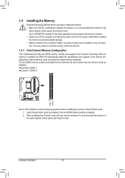
A memory module can be used . (Go to GIGABYTE's website for the latest supported memory speeds and memory...two DDR3 memory sockets are unable to insert the memory, switch the direction. 1-4-1 Dual Channel Memory Configuration This motherboard provides two DDR3 memory sockets and supports Dual Channel Technology. DDR3_1 DDR3_2 Hardware Installation - 16 - 1-4 Installing...of the same capacity, brand, speed, and chips be used . After the memory is recommended that the motherboard supports the memory. It is installed. 2. When enabling Dual Channel mode with two memory modules,it is ...
A memory module can be used . (Go to GIGABYTE's website for the latest supported memory speeds and memory...two DDR3 memory sockets are unable to insert the memory, switch the direction. 1-4-1 Dual Channel Memory Configuration This motherboard provides two DDR3 memory sockets and supports Dual Channel Technology. DDR3_1 DDR3_2 Hardware Installation - 16 - 1-4 Installing...of the same capacity, brand, speed, and chips be used . After the memory is recommended that the motherboard supports the memory. It is installed. 2. When enabling Dual Channel mode with two memory modules,it is ...
Manual
Page 17
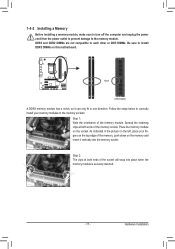
... of the socket will snap into the memory socket. Step 2: The clips at both ends of the memory module. Place the memory module on this motherboard. 1-4-2 Installing a Memory Before installing a memory module, make sure to turn off the computer and unplug the power cord from the power outlet to prevent damage...
... of the socket will snap into the memory socket. Step 2: The clips at both ends of the memory module. Place the memory module on this motherboard. 1-4-2 Installing a Memory Before installing a memory module, make sure to turn off the computer and unplug the power cord from the power outlet to prevent damage...

Manual
Page 18
... the expansion slot. 1. Remove the metal slot cover from the slot. Secure the card's metal bracket to install an expansion card: • Make sure the motherboard supports the expansion card. Make sure the metal contacts on the card until it is securely seated in your expansion card. • Always turn off...
... the expansion slot. 1. Remove the metal slot cover from the slot. Secure the card's metal bracket to install an expansion card: • Make sure the motherboard supports the expansion card. Make sure the metal contacts on the card until it is securely seated in your expansion card. • Always turn off...
Manual
Page 19
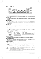
... of the LAN port LEDs. Use this port. Mic In Jack (Pink) The default Mic in jack. Do not rock it straight out from the motherboard. • When removing the cable, pull it side to side to this jack. The following de- Hardware Installation D-Sub Port The D-Sub port supports a 15...
... of the LAN port LEDs. Use this port. Mic In Jack (Pink) The default Mic in jack. Do not rock it straight out from the motherboard. • When removing the cable, pull it side to side to this jack. The following de- Hardware Installation D-Sub Port The D-Sub port supports a 15...
Manual
Page 20
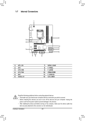
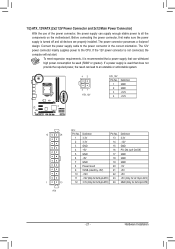
... devices and your devices are compliant with the connectors you wish to connect. • Before installing the devices, be sure to the connector on the motherboard. Hardware Installation - 20 - 1-7 Internal Connectors 1 2 3 5 12 6 4 7 8 9 10 11 1) ATX_12V 2) ATX 3) CPU_FAN 4) SYS_FAN 5) BAT 6) SATA3_0/1 7) SATA2_2/3/4/5 8) F_PANEL 9) F_AUDIO 10) COMA/COMB 11) F_USB1/2/3 12) CLR_CMOS Read...
... devices and your devices are compliant with the connectors you wish to connect. • Before installing the devices, be sure to the connector on the motherboard. Hardware Installation - 20 - 1-7 Internal Connectors 1 2 3 5 12 6 4 7 8 9 10 11 1) ATX_12V 2) ATX 3) CPU_FAN 4) SYS_FAN 5) BAT 6) SATA3_0/1 7) SATA2_2/3/4/5 8) F_PANEL 9) F_AUDIO 10) COMA/COMB 11) F_USB1/2/3 12) CLR_CMOS Read...
Manual
Page 21
... power connector mainly supplies power to the power connector in the correct orientation. If a power supply is turned off and all the components on the motherboard. The power connector possesses a foolproof design. Before connecting the power connector, first make sure the power supply is used that can withstand high power consumption...
... power connector mainly supplies power to the power connector in the correct orientation. If a power supply is turned off and all the components on the motherboard. The power connector possesses a foolproof design. Before connecting the power connector, first make sure the power supply is used that can withstand high power consumption...

Manual
Page 22
...positive side (+) and the negative side (-) of the battery (the positive side should face up). • Used batteries must be lost. The motherboard supports CPU fan speed control, which requires the use a metal object like a screwdriver to the CPU or the system may be handled in ...Replace the battery with an incorrect model. • Contact the place of the battery holder, making them short for one . 3/4) CPU_FAN/SYS_FAN (Fan Headers) The motherboard has a 4-pin CPU fan header (CPU_FAN) and a 4-pin (SYS_FAN) fan header. Do not place a jumper cap on the headers. 5) BAT (Battery) ...
...positive side (+) and the negative side (-) of the battery (the positive side should face up). • Used batteries must be lost. The motherboard supports CPU fan speed control, which requires the use a metal object like a screwdriver to the CPU or the system may be handled in ...Replace the battery with an incorrect model. • Contact the place of the battery holder, making them short for one . 3/4) CPU_FAN/SYS_FAN (Fan Headers) The motherboard has a 4-pin CPU fan header (CPU_FAN) and a 4-pin (SYS_FAN) fan header. Do not place a jumper cap on the headers. 5) BAT (Battery) ...
Manual
Page 25
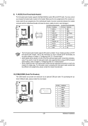
...your chassis front panel audio module to activate AC'97 functionality via an optional COM port cable. Incorrect connection between the module connector and the motherboard header will be present on how to this header. 9) F_AUDIO (Front Panel Audio Header) The front panel audio header supports Intel High Definition ... AC'97 audio. You may connect your chassis provides an AC'97 front panel audio module, refer to the instructions on both of the motherboard header. For HD Front Panel Audio: For AC'97 Front Panel Audio: Pin No. nector match the pin assignments of the front and ...
...your chassis front panel audio module to activate AC'97 functionality via an optional COM port cable. Incorrect connection between the module connector and the motherboard header will be present on how to this header. 9) F_AUDIO (Front Panel Audio Header) The front panel audio header supports Intel High Definition ... AC'97 audio. You may connect your chassis provides an AC'97 front panel audio module, refer to the instructions on both of the motherboard header. For HD Front Panel Audio: For AC'97 Front Panel Audio: Pin No. nector match the pin assignments of the front and ...


