
Manual
Page 1
GA-H67A-UD3H LGA1155 socket motherboard for Intel® Core™ i7 processors/ Intel® Core™ i5 processors/Intel® Core™ i3 processors/ Intel® Pentium® processors/Intel® Celeron® processors User's Manual Rev. 1002 12ME-H67UD3H-1002R
GA-H67A-UD3H LGA1155 socket motherboard for Intel® Core™ i7 processors/ Intel® Core™ i5 processors/Intel® Core™ i3 processors/ Intel® Pentium® processors/Intel® Celeron® processors User's Manual Rev. 1002 12ME-H67UD3H-1002R

Manual
Page 2
Motherboard GA-H67A-UD3H Oct. 29, 2010 Motherboard GA-H67A-UD3H Oct. 29, 2010
Motherboard GA-H67A-UD3H Oct. 29, 2010 Motherboard GA-H67A-UD3H Oct. 29, 2010
Manual
Page 3
...rights reserved. For product-related information, check on our website at: http://www.gigabyte.com Identifying Your Motherboard Revision The revision number on your motherboard revision before updating motherboard BIOS, drivers, or when looking for technical information. Documentation Classifications In order to ...LTD. Disclaimer Information in this product, GIGABYTE provides the following types of documentations: For quick set-up of this manual may be made by GIGABYTE without GIGABYTE's prior written permission. Check your motherboard looks like this manual is protected by ...
...rights reserved. For product-related information, check on our website at: http://www.gigabyte.com Identifying Your Motherboard Revision The revision number on your motherboard revision before updating motherboard BIOS, drivers, or when looking for technical information. Documentation Classifications In order to ...LTD. Disclaimer Information in this product, GIGABYTE provides the following types of documentations: For quick set-up of this manual may be made by GIGABYTE without GIGABYTE's prior written permission. Check your motherboard looks like this manual is protected by ...

Manual
Page 4
Table of Contents Box Contents...6 Optional Items...6 GA-H67A-UD3H Motherboard Layout 7 GA-H67A-UD3H Motherboard Block Diagram 8 Chapter 1 Hardware Installation 9 1-1 Installation Precautions 9 1-2 Product Specifications 10 1-3 Installing the CPU and CPU Cooler 13 1-3-1 Installing the CPU 13 1-3-2 Installing the CPU Cooler ...
Table of Contents Box Contents...6 Optional Items...6 GA-H67A-UD3H Motherboard Layout 7 GA-H67A-UD3H Motherboard Block Diagram 8 Chapter 1 Hardware Installation 9 1-1 Installation Precautions 9 1-2 Product Specifications 10 1-3 Installing the CPU and CPU Cooler 13 1-3-1 Installing the CPU 13 1-3-2 Installing the CPU Cooler ...

Manual
Page 6
The box contents are for reference only. Box Contents GA-H67A-UD3H motherboard Motherboard driver disk User's Manual Quick Installation Guide Four SATA cables I/O Shield • The box contents above are subject to change without notice. • The motherboard image is for reference only and the actual items shall depend on the product package you obtain. Optional Items 2-port USB 2.0 bracket (Part No. 12CR1-1UB030-5*R) 2-port IEEE 1394a bracket (Part No. 12CF1-1IE008-0*R) 2-port SATA power cable (Part No. 12CF1-2SERPW-0*R) COM port cable (Part No. 12CF1-1CM001-3*R) - 6 -
The box contents are for reference only. Box Contents GA-H67A-UD3H motherboard Motherboard driver disk User's Manual Quick Installation Guide Four SATA cables I/O Shield • The box contents above are subject to change without notice. • The motherboard image is for reference only and the actual items shall depend on the product package you obtain. Optional Items 2-port USB 2.0 bracket (Part No. 12CR1-1UB030-5*R) 2-port IEEE 1394a bracket (Part No. 12CF1-1IE008-0*R) 2-port SATA power cable (Part No. 12CF1-2SERPW-0*R) COM port cable (Part No. 12CF1-1CM001-3*R) - 6 -

Manual
Page 7
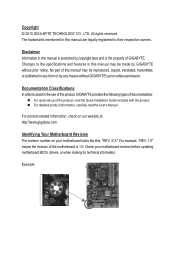
TSB43AB23 F_PANEL COMA SYS_FAN1 F_1394_1 F_USB4 F_USB2 F_1394_2 F_USB5 F_USB3 F_USB1 - 7 - GA-H67A-UD3H Motherboard Layout KB_USB CPU_FAN ATX_12V_2X4 VGA_DVI LGA1155 PHASE LED DP_HDMI_SPDIF PWR_FAN ESATA_1394_USB USB30_LAN Renesas D720200 AUDIO PCIEX1_1 F_AUDIO Realtek RTL8111E PCIEX16 PCIEX1_2 CODEC PCIEX4 SPDIF_O PCI1 iTE PCI2 IT8728 PCI3 ATX GA-H67A-UD3H DDR3_1 DDR3_2 DDR3_3 DDR3_4 BAT CLR_CMOS Intel® H67 B_BIOS M_BIOS iTE IT8892 Bridge SYS_FAN2 SATA2_2 SATA2_3 SATA3_0 SATA2_4 SATA3_1 T.I.
TSB43AB23 F_PANEL COMA SYS_FAN1 F_1394_1 F_USB4 F_USB2 F_1394_2 F_USB5 F_USB3 F_USB1 - 7 - GA-H67A-UD3H Motherboard Layout KB_USB CPU_FAN ATX_12V_2X4 VGA_DVI LGA1155 PHASE LED DP_HDMI_SPDIF PWR_FAN ESATA_1394_USB USB30_LAN Renesas D720200 AUDIO PCIEX1_1 F_AUDIO Realtek RTL8111E PCIEX16 PCIEX1_2 CODEC PCIEX4 SPDIF_O PCI1 iTE PCI2 IT8728 PCI3 ATX GA-H67A-UD3H DDR3_1 DDR3_2 DDR3_3 DDR3_4 BAT CLR_CMOS Intel® H67 B_BIOS M_BIOS iTE IT8892 Bridge SYS_FAN2 SATA2_2 SATA2_3 SATA3_0 SATA2_4 SATA3_1 T.I.

Manual
Page 8
GA-H67A-UD3H Motherboard Block Diagram 1 PCI Express x16 PCIe CLK (100 MHz) LGA1155 CPU CPU CLK+/- (100 MHz) DDR3 1333/1066/800 MHz Dual Channel Memory PCI Express ...
GA-H67A-UD3H Motherboard Block Diagram 1 PCI Express x16 PCIe CLK (100 MHz) LGA1155 CPU CPU CLK+/- (100 MHz) DDR3 1333/1066/800 MHz Dual Channel Memory PCI Express ...

Manual
Page 9
...wrist strap when handling electronic com- If you are uncertain about any metal leads or connectors. • It is best to installing the motherboard, please have it on top of an antistatic pad or within the computer casing. • Do not place the computer system on an... of the product, please consult a certified computer technician. - 9 - These stickers are connected tightly and securely. • When handling the motherboard, avoid touching any installation steps or have a problem related to the use of your hardware components are connected. • To prevent damage to the...
...wrist strap when handling electronic com- If you are uncertain about any metal leads or connectors. • It is best to installing the motherboard, please have it on top of an antistatic pad or within the computer casing. • Do not place the computer system on an... of the product, please consult a certified computer technician. - 9 - These stickers are connected tightly and securely. • When handling the motherboard, avoid touching any installation steps or have a problem related to the use of your hardware components are connected. • To prevent damage to the...

Manual
Page 12
... Charge Support for Cloud OC Support for Q-Share Norton Internet Security (OEM version) Operating System w Support for EasyTune * Available functions in EasyTune may differ by motherboard model. Hardware Installation - 12 - I/O Controller w Hardware Monitor w w w w w w BIOS w w w w Unique Features w w w w w w w w w ... w ATX Form Factor; 30.5cm x 24.4cm * GIGABYTE reserves the right to make any changes to the product specifications and product-related information without prior notice...
... Charge Support for Cloud OC Support for Q-Share Norton Internet Security (OEM version) Operating System w Support for EasyTune * Available functions in EasyTune may differ by motherboard model. Hardware Installation - 12 - I/O Controller w Hardware Monitor w w w w w w BIOS w w w w Unique Features w w w w w w w w w ... w ATX Form Factor; 30.5cm x 24.4cm * GIGABYTE reserves the right to make any changes to the product specifications and product-related information without prior notice...

Manual
Page 13
... Socket Alignment Key Alignment Key Pin One Corner of thermal grease on the computer if the CPU cooler is not recommended that the motherboard supports the CPU. (Go to GIGABYTE's website for the peripherals. The CPU cannot be set the frequency beyond hardware specifications since it does not meet the standard requirements... occur. • Set the CPU host frequency in accordance with the CPU specifications. Hardware Installation age of the CPU. Locate the alignment keys on the motherboard CPU socket and the notches on the CPU - 13 -
... Socket Alignment Key Alignment Key Pin One Corner of thermal grease on the computer if the CPU cooler is not recommended that the motherboard supports the CPU. (Go to GIGABYTE's website for the peripherals. The CPU cannot be set the frequency beyond hardware specifications since it does not meet the standard requirements... occur. • Set the CPU host frequency in accordance with the CPU specifications. Hardware Installation age of the CPU. Locate the alignment keys on the motherboard CPU socket and the notches on the CPU - 13 -

Manual
Page 14
... metal load plate will be lifted as shown. Hold your thumb to lift up the front edge (next to correctly install the CPU into the motherboard CPU socket. To protect the CPU socket, always replace the protective socket cover when the CPU is not installed.) Step 3: Hold the CPU with the...
... metal load plate will be lifted as shown. Hold your thumb to lift up the front edge (next to correctly install the CPU into the motherboard CPU socket. To protect the CPU socket, always replace the protective socket cover when the CPU is not installed.) Step 3: Hold the CPU with the...

Manual
Page 15
...5: After the installation, check the back of the CPU cooler to the CPU fan header (CPU_FAN) on the motherboard. Step 6: Finally, attach the power connector of the motherboard. Hardware Installation Use extreme care when removing the CPU cooler because the thermal grease/tape between the CPU cooler and...the CPU cooler may adhere to the CPU. 1-3-2 Installing the CPU Cooler Follow the steps below to correctly install the CPU cooler on the motherboard. (The following procedure uses Intel® boxed cooler as the picture above shows, the installation is to install.) Step 3: Place the ...
...5: After the installation, check the back of the CPU cooler to the CPU fan header (CPU_FAN) on the motherboard. Step 6: Finally, attach the power connector of the motherboard. Hardware Installation Use extreme care when removing the CPU cooler because the thermal grease/tape between the CPU cooler and...the CPU cooler may adhere to the CPU. 1-3-2 Installing the CPU Cooler Follow the steps below to correctly install the CPU cooler on the motherboard. (The following procedure uses Intel® boxed cooler as the picture above shows, the installation is to install.) Step 3: Place the ...

Manual
Page 16
...(SS=Single-Sided, DS=Double-Sided, "- -"=No Memory) DDR3_1 DDR3_2 DDR3_3 DDR3_4 Due to install the memory: • Make sure that the motherboard supports the memory. If you begin to CPU limitations, read the following : Channel 0: DDR3_1, DDR3_2 Channel 1: DDR3_3, DDR3_4 Dual Channel Memory Configurations... installing the memory in only one DDR3 memory module is recommended that memory of the memory. The four DDR3 memory sockets are unable to GIGABYTE's website for optimum performance. DS/SS - - - - When enabling Dual Channel mode with two or four memory modules, it is ...
...(SS=Single-Sided, DS=Double-Sided, "- -"=No Memory) DDR3_1 DDR3_2 DDR3_3 DDR3_4 Due to install the memory: • Make sure that the motherboard supports the memory. If you begin to CPU limitations, read the following : Channel 0: DDR3_1, DDR3_2 Channel 1: DDR3_3, DDR3_4 Dual Channel Memory Configurations... installing the memory in only one DDR3 memory module is recommended that memory of the memory. The four DDR3 memory sockets are unable to GIGABYTE's website for optimum performance. DS/SS - - - - When enabling Dual Channel mode with two or four memory modules, it is ...

Manual
Page 17
... DIMMs are not compatible to each other or DDR DIMMs. Be sure to install DDR3 DIMMs on the socket. Place the memory module on this motherboard. Step 1: Note the orientation of the memory, push down on the left, place your memory modules in one direction. Follow the steps below to the...
... DIMMs are not compatible to each other or DDR DIMMs. Be sure to install DDR3 DIMMs on the socket. Place the memory module on this motherboard. Step 1: Note the orientation of the memory, push down on the left, place your memory modules in one direction. Follow the steps below to the...

Manual
Page 18
... before you begin to the chassis back panel with your card. Secure the card's metal bracket to install an expansion card: • Make sure the motherboard supports the expansion card. If necessary, go to BIOS Setup to correctly install your computer. Install the driver provided with the slot, and press down...
... before you begin to the chassis back panel with your card. Secure the card's metal bracket to install an expansion card: • Make sure the motherboard supports the expansion card. If necessary, go to BIOS Setup to correctly install your computer. Install the driver provided with the slot, and press down...

Manual
Page 20
Use this port for the Onboard Graphics: This motherboard provides four video output ports: D-Sub, DVI-D, HDMI, and DisplayPort. Hardware Installation - 20 - After installing the DisplayPort device, make sure the default device for an ...
Use this port for the Onboard Graphics: This motherboard provides four video output ports: D-Sub, DVI-D, HDMI, and DisplayPort. Hardware Installation - 20 - After installing the DisplayPort device, make sure the default device for an ...

Manual
Page 21
... Audio." • When removing the cable connected to prevent an electrical short inside the cable connector. - 21 - Do not rock it straight out from the motherboard. • When removing the cable, pull it side to side to a back panel connector, first remove the cable from your device and then remove it...
... Audio." • When removing the cable connected to prevent an electrical short inside the cable connector. - 21 - Do not rock it straight out from the motherboard. • When removing the cable, pull it side to side to a back panel connector, first remove the cable from your device and then remove it...

Manual
Page 22
..., make sure your devices are compliant with the connectors you wish to connect. • Before installing the devices, be sure to the connector on the motherboard.
..., make sure your devices are compliant with the connectors you wish to connect. • Before installing the devices, be sure to the connector on the motherboard.

Manual
Page 23
... an unstable or unbootable system. 8 4 5 1 ATX_12V_2X4 ATX_12V_2X4: Pin No. Hardware Installation If the 12V power connector is turned off and all the components on the motherboard. If a power supply is recommended that a power supply that does not provide the required power, the result can withstand high power consumption be used that...
... an unstable or unbootable system. 8 4 5 1 ATX_12V_2X4 ATX_12V_2X4: Pin No. Hardware Installation If the 12V power connector is turned off and all the components on the motherboard. If a power supply is recommended that a power supply that does not provide the required power, the result can withstand high power consumption be used that...

Manual
Page 24
...Sense • Be sure to connect fan cables to the fan headers to connect it is the ground wire). Hardware Installation - 24 - The motherboard supports CPU fan speed control, which requires the use of a CPU fan with fan speed control design. Definition 1 GND 1 2 +12V / ...Speed Control SYS_FAN1 3 Sense 4 Reserve SYS_FAN2/PWR_FAN: Pin No. 3/4/5) CPU_FAN/SYS_FAN1/SYS_FAN2/PWR_FAN (Fan Headers) The motherboard has a 4-pin CPU fan header (CPU_FAN), a 4-pin (SYS_FAN1) and a 3-pin system fans, and a 3-pin power fan. For optimum heat dissipation,...
...Sense • Be sure to connect fan cables to the fan headers to connect it is the ground wire). Hardware Installation - 24 - The motherboard supports CPU fan speed control, which requires the use of a CPU fan with fan speed control design. Definition 1 GND 1 2 +12V / ...Speed Control SYS_FAN1 3 Sense 4 Reserve SYS_FAN2/PWR_FAN: Pin No. 3/4/5) CPU_FAN/SYS_FAN1/SYS_FAN2/PWR_FAN (Fan Headers) The motherboard has a 4-pin CPU fan header (CPU_FAN), a 4-pin (SYS_FAN1) and a 3-pin system fans, and a 3-pin power fan. For optimum heat dissipation,...


