
Manual
Page 1
GA-H61M-D2P-B3 LGA1155 socket motherboard for Intel® Core™ i7 processor family/ Intel® Core™ i5 processor family/Intel® Core™ i3 processor family/ Intel® Pentium® processors/Intel® Celeron® processors User's Manual Rev. 1002 12ME-H61M2PB-1002R
GA-H61M-D2P-B3 LGA1155 socket motherboard for Intel® Core™ i7 processor family/ Intel® Core™ i5 processor family/Intel® Core™ i3 processor family/ Intel® Pentium® processors/Intel® Celeron® processors User's Manual Rev. 1002 12ME-H61M2PB-1002R

Manual
Page 2
Motherboard GA-H61M-D2P-B3 Jan. 28, 2011 Motherboard GA-H61M-D2P-B3 Jan. 28, 2011
Motherboard GA-H61M-D2P-B3 Jan. 28, 2011 Motherboard GA-H61M-D2P-B3 Jan. 28, 2011
Manual
Page 3
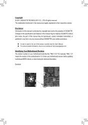
... Information in any form or by any means without prior notice. Changes to the specifications and features in the use of GIGABYTE. For example, "REV: 1.0" means the revision of the motherboard is the property of this manual may be made by copyright laws and is 1.0. The trademarks mentioned in this manual are...
... Information in any form or by any means without prior notice. Changes to the specifications and features in the use of GIGABYTE. For example, "REV: 1.0" means the revision of the motherboard is the property of this manual may be made by copyright laws and is 1.0. The trademarks mentioned in this manual are...

Manual
Page 4
Table of Contents GA-H61M-D2P-B3 Motherboard Layout 5 Chapter 1 Hardware Installation 6 1-1 Installation Precautions 6 1-2 Product Specifications 7 1-3 Installing the CPU and CPU Cooler 9 1-4 Installing the Memory 10 1-5 Installing an Expansion Card 10 1-6 Back Panel ...
Table of Contents GA-H61M-D2P-B3 Motherboard Layout 5 Chapter 1 Hardware Installation 6 1-1 Installation Precautions 6 1-2 Product Specifications 7 1-3 Installing the CPU and CPU Cooler 9 1-4 Installing the Memory 10 1-5 Installing an Expansion Card 10 1-6 Back Panel ...

Manual
Page 5
GA-H61M-D2P-B3 Motherboard Layout KB_MS ATX_12V VGA_DVI R_USB1 CPU_FAN LGA1155 R_USB2 ATX USB_LAN AUDIO Realtek RTL8111E PCIe to PCI BAT Bridge CODEC PCIEX16 PCI1 iTE IT8728 PCI2 GA-H61M-D2P-B3 DDR3_1 DDR3_2 B_BIOS M_BIOS Intel® H61 CLR_CMOS SYS_FAN PCIEX4 F_AUDIO COMA LPT Box Contents GA-H61M-D2P-B3 motherboard User's Manual I/O Shield SATA2_0 SATA2_1 SATA2_2 SATA2_3 F_PANEL F_USB2 F_USB1 Motherboard driver disk Two SATA cables The box contents above are for reference only and the actual items shall depend on the product package you obtain. - 5 -
GA-H61M-D2P-B3 Motherboard Layout KB_MS ATX_12V VGA_DVI R_USB1 CPU_FAN LGA1155 R_USB2 ATX USB_LAN AUDIO Realtek RTL8111E PCIe to PCI BAT Bridge CODEC PCIEX16 PCI1 iTE IT8728 PCI2 GA-H61M-D2P-B3 DDR3_1 DDR3_2 B_BIOS M_BIOS Intel® H61 CLR_CMOS SYS_FAN PCIEX4 F_AUDIO COMA LPT Box Contents GA-H61M-D2P-B3 motherboard User's Manual I/O Shield SATA2_0 SATA2_1 SATA2_2 SATA2_3 F_PANEL F_USB2 F_USB1 Motherboard driver disk Two SATA cables The box contents above are for reference only and the actual items shall depend on the product package you obtain. - 5 -

Manual
Page 6
...off. •• Before turning on the power, make sure they are connected tightly and securely. •• When handling the motherboard, avoid touching any installation steps or have a problem related to the use of the product, please consult a certified computer technician. ...Chapter 1 Hardware Installation 1-1 Installation Precautions The motherboard contains numerous delicate electronic circuits and components which can lead to damage to system components as well as physical harm to the user...
...off. •• Before turning on the power, make sure they are connected tightly and securely. •• When handling the motherboard, avoid touching any installation steps or have a problem related to the use of the product, please consult a certified computer technician. ...Chapter 1 Hardware Installation 1-1 Installation Precautions The motherboard contains numerous delicate electronic circuits and components which can lead to damage to system components as well as physical harm to the user...

Manual
Page 8
... Center ŠŠ Support for Xpress Install ŠŠ Support for Xpress Recovery2 ŠŠ Support for EasyTune * Available functions in EasyTune may differ by motherboard model. ŠŠ Support for Smart 6™ ŠŠ Support for Auto Green ŠŠ Support for ON/OFF Charge ŠŠ Support for Cloud...
... Center ŠŠ Support for Xpress Install ŠŠ Support for Xpress Recovery2 ŠŠ Support for EasyTune * Available functions in EasyTune may differ by motherboard model. ŠŠ Support for Smart 6™ ŠŠ Support for Auto Green ŠŠ Support for ON/OFF Charge ŠŠ Support for Cloud...

Manual
Page 9
... thin layer of thermal grease on the computer if the CPU cooler is not recommended that the motherboard supports the CPU. (Go to GIGABYTE's website for the peripherals. Hardware Installation Locate the alignment keys on the motherboard CPU socket and the notches on the CPU - 9 - LGA1155 CPU Socket Alignment Key Alignment Key Pin...
... thin layer of thermal grease on the computer if the CPU cooler is not recommended that the motherboard supports the CPU. (Go to GIGABYTE's website for the peripherals. Hardware Installation Locate the alignment keys on the motherboard CPU socket and the notches on the CPU - 9 - LGA1155 CPU Socket Alignment Key Alignment Key Pin...

Manual
Page 10
...memory mode will automatically detect the specifications and capacity of the same capacity, brand, speed, and chips be used . (Go to GIGABYTE's website for optimum performance. 1-5 Installing an Expansion Card Read the following guidelines before installing the memory to prevent hardware damage. The two... DDR3 memory sockets are unable to install an expansion card: •• Make sure the motherboard supports the expansion card. Hardware Installation - 10 - A memory module can be enabled if only one direction. It is recommended that...
...memory mode will automatically detect the specifications and capacity of the same capacity, brand, speed, and chips be used . (Go to GIGABYTE's website for optimum performance. 1-5 Installing an Expansion Card Read the following guidelines before installing the memory to prevent hardware damage. The two... DDR3 memory sockets are unable to install an expansion card: •• Make sure the motherboard supports the expansion card. Hardware Installation - 10 - A memory module can be enabled if only one direction. It is recommended that...

Manual
Page 11
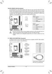
... to the instructions on the monitor being used to a back panel connector, first remove the cable from your device and then remove it from the motherboard. •• When removing the cable, pull it side to side to the DVI-D specification and supports a maximum resolution of the LAN port LEDs. Hardware...
... to the instructions on the monitor being used to a back panel connector, first remove the cable from your device and then remove it from the motherboard. •• When removing the cable, pull it side to side to the DVI-D specification and supports a maximum resolution of the LAN port LEDs. Hardware...

Manual
Page 12
... and your devices are compliant with the connectors you wish to connect. •• Before installing the devices, be sure to the connector on the motherboard. 1-7 Internal Connectors 1 3 2 12 4 7 10 1) ATX_12V 2) ATX 3) CPU_FAN 4) SYS_FAN 5) SATA2_0/1/2/3 6) F_PANEL 11 5 9 6 8 7) F_AUDIO 8) F_USB1/F_USB2 9) LPT 10) COMA 11) CLR_CMOS 12) BAT Read the following guidelines...
... and your devices are compliant with the connectors you wish to connect. •• Before installing the devices, be sure to the connector on the motherboard. 1-7 Internal Connectors 1 3 2 12 4 7 10 1) ATX_12V 2) ATX 3) CPU_FAN 4) SYS_FAN 5) SATA2_0/1/2/3 6) F_PANEL 11 5 9 6 8 7) F_AUDIO 8) F_USB1/F_USB2 9) LPT 10) COMA 11) CLR_CMOS 12) BAT Read the following guidelines...

Manual
Page 13
... all devices are properly installed. The power connector possesses a foolproof design. If the 12V power connector is turned off and all the components on the motherboard. Hardware Installation 1/2) ATX_12V/ATX (2x2 12V Power Connector and 2x12 Main Power Connector) With the use of the power connector, the power supply can lead...
... all devices are properly installed. The power connector possesses a foolproof design. If the 12V power connector is turned off and all the components on the motherboard. Hardware Installation 1/2) ATX_12V/ATX (2x2 12V Power Connector and 2x12 Main Power Connector) With the use of the power connector, the power supply can lead...
Manual
Page 14
The motherboard supports CPU fan speed control, which requires the use of the SATA cable to the CPU or the system may result in the correct orientation (... black connector wire is recommended that a system fan be sure to SATA 3Gb/s standard and are not configuration jumper blocks. 3/4) CPU_FAN/SYS_FAN (Fan Headers) The motherboard has a 4-pin CPU fan header (CPU_FAN) and a 4-pin system fan header (SYS_FAN). Do not place a jumper cap on the headers. 5) SATA2_0/1/2/3 (SATA 3Gb/s Connectors) The...
The motherboard supports CPU fan speed control, which requires the use of the SATA cable to the CPU or the system may result in the correct orientation (... black connector wire is recommended that a system fan be sure to SATA 3Gb/s standard and are not configuration jumper blocks. 3/4) CPU_FAN/SYS_FAN (Fan Headers) The motherboard has a 4-pin CPU fan header (CPU_FAN) and a 4-pin system fan header (SYS_FAN). Do not place a jumper cap on the headers. 5) SATA2_0/1/2/3 (SATA 3Gb/s Connectors) The...

Manual
Page 16
... audio. Make sure the wire assignments of the module connector match the pin assignments of a single plug. Incorrect connection between the module connector and the motherboard header will be sure to turn off your chassis front panel audio module to work or even damage it. Definition 1 Power (5V) 9 1 10 2 2 Power (5V... 1394 bracket (2x5-pin) cable into the USB header. •• Prior to installing the USB bracket, be present on each wire instead of the motherboard header.
... audio. Make sure the wire assignments of the module connector match the pin assignments of a single plug. Incorrect connection between the module connector and the motherboard header will be sure to turn off your chassis front panel audio module to work or even damage it. Definition 1 Power (5V) 9 1 10 2 2 Power (5V... 1394 bracket (2x5-pin) cable into the USB header. •• Prior to installing the USB bracket, be present on each wire instead of the motherboard header.

Manual
Page 18
... as BIOS configurations, date, and time information) in the CMOS when the computer is replaced with local environmental regulations. You may cause damage to the motherboard. •• After system restart, go to BIOS Setup to load factory defaults (select Load Optimized Defaults) or manually configure the BIOS settings (refer to...
... as BIOS configurations, date, and time information) in the CMOS when the computer is replaced with local environmental regulations. You may cause damage to the motherboard. •• After system restart, go to BIOS Setup to load factory defaults (select Load Optimized Defaults) or manually configure the BIOS settings (refer to...

Manual
Page 19
If this chapter or introductions of the BIOS Setup program. H61M-D2P-B3 E10 . . . . : BIOS Setup : XpressRecovery2 : Boot Menu : Qflash 12/...boot. Inadequate BIOS flashing may result in system's failure to prevent system instability or other unexpected results. Motherboard Model BIOS Version Award Modular BIOS v6.00PG Copyright (C) 1984-2010, Award Software, Inc. To flash ... problems using the current version of BIOS from BIOS - 19 - To upgrade the BIOS, use either the GIGABYTE Q-Flash or @BIOS utility. •• Q-Flash allows the user to clear the CMOS values.) 2-1 ...
If this chapter or introductions of the BIOS Setup program. H61M-D2P-B3 E10 . . . . : BIOS Setup : XpressRecovery2 : Boot Menu : Qflash 12/...boot. Inadequate BIOS flashing may result in system's failure to prevent system instability or other unexpected results. Motherboard Model BIOS Version Award Modular BIOS v6.00PG Copyright (C) 1984-2010, Award Software, Inc. To flash ... problems using the current version of BIOS from BIOS - 19 - To upgrade the BIOS, use either the GIGABYTE Q-Flash or @BIOS utility. •• Q-Flash allows the user to clear the CMOS values.) 2-1 ...
Manual
Page 31
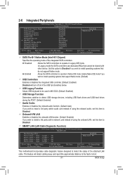
...; Move Enter: Select F5: Previous Values +/-/PU/PD: Value F10: Save F6: Fail-Safe Defaults ESC: Exit F1: General Help F7: Optimized Defaults This motherboard incorporates cable diagnostic feature designed to detect the status of using the onboard LAN, set this item to install a 3rd party add-in audio card...
...; Move Enter: Select F5: Previous Values +/-/PU/PD: Value F10: Save F6: Fail-Safe Defaults ESC: Exit F1: General Help F7: Optimized Defaults This motherboard incorporates cable diagnostic feature designed to detect the status of using the onboard LAN, set this item to install a 3rd party add-in audio card...

Manual
Page 34
... Displays current system/CPU temperature. CPU Warning Temperature Sets the warning threshold for CPU temperature. CPU/SYSTEM FAN Fail Warning Allows the system to the motherboard CI header. Check the fan condition or fan connection when this field will show "Yes", otherwise it will emit warning sound. You can adjust the...
... Displays current system/CPU temperature. CPU Warning Temperature Sets the warning threshold for CPU temperature. CPU/SYSTEM FAN Fail Warning Allows the system to the motherboard CI header. Check the fan condition or fan connection when this field will show "Yes", otherwise it will emit warning sound. You can adjust the...

Manual
Page 35
... CMOS to BIOS F12: Load CMOS from BIOS Press on this item and then press the key to Manual. PWM Sets PWM mode for the motherboard. 2-10 Load Optimized Defaults CMOS Setup Utility-Copyright (C) 1984-2010 Award Software MB Intelligent Tweaker(M.I .T.) Load Fail-Safe Defaults Standard CMOS Features Load...
... CMOS to BIOS F12: Load CMOS from BIOS Press on this item and then press the key to Manual. PWM Sets PWM mode for the motherboard. 2-10 Load Optimized Defaults CMOS Setup Utility-Copyright (C) 1984-2010 Award Software MB Intelligent Tweaker(M.I .T.) Load Fail-Safe Defaults Standard CMOS Features Load...

Manual
Page 37
Chapter 3 Drivers Installation • Before installing the drivers, first install the operating system. • After installing the operating system, insert the motherboard driver disk into your optical drive. The driver Autorun screen is automatically displayed which looks like that shown in BIOS Setup to My Computer, double-...
Chapter 3 Drivers Installation • Before installing the drivers, first install the operating system. • After installing the operating system, insert the motherboard driver disk into your optical drive. The driver Autorun screen is automatically displayed which looks like that shown in BIOS Setup to My Computer, double-...


