
Manual
Page 3
...on how to their respective owners. For example, "REV: 1.0" means the revision of this manual is protected by GIGABYTE without GIGABYTE's prior written permission. The trademarks mentioned in any form or by any means without prior notice. For detailed product information..., carefully read the Quick Installation Guide included with the product. For instructions on your motherboard revision before updating motherboard BIOS, ...
...on how to their respective owners. For example, "REV: 1.0" means the revision of this manual is protected by GIGABYTE without GIGABYTE's prior written permission. The trademarks mentioned in any form or by any means without prior notice. For detailed product information..., carefully read the Quick Installation Guide included with the product. For instructions on your motherboard revision before updating motherboard BIOS, ...
Manual
Page 4
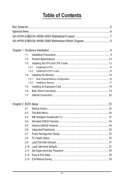
Table of Contents Box Contents...6 Optional Items...6 GA-H57M-USB3/GA-H55M-USB3 Motherboard Layout 7 GA-H57M-USB3/GA-H55M-USB3 Motherboard Block Diagram 8 Chapter 1 Hardware Installation 9 1-1 Installation Precautions 9 1-2 Product Specifications 10 1-3 Installing the CPU... Expansion Card 18 1-6 Back Panel Connectors 19 1-7 Internal Connectors 22 Chapter 2 BIOS Setup 33 2-1 Startup Screen 34 2-2 The Main Menu 35 2-3 MB Intelligent Tweaker(M.I.T 37 2-4 Standard CMOS Features 46 2-5 Advanced BIOS Features 48 2-6 Integrated Peripherals 50 2-7 Power Management Setup 53 2-8 PC Health ...
Table of Contents Box Contents...6 Optional Items...6 GA-H57M-USB3/GA-H55M-USB3 Motherboard Layout 7 GA-H57M-USB3/GA-H55M-USB3 Motherboard Block Diagram 8 Chapter 1 Hardware Installation 9 1-1 Installation Precautions 9 1-2 Product Specifications 10 1-3 Installing the CPU... Expansion Card 18 1-6 Back Panel Connectors 19 1-7 Internal Connectors 22 Chapter 2 BIOS Setup 33 2-1 Startup Screen 34 2-2 The Main Menu 35 2-3 MB Intelligent Tweaker(M.I.T 37 2-4 Standard CMOS Features 46 2-5 Advanced BIOS Features 48 2-6 Integrated Peripherals 50 2-7 Power Management Setup 53 2-8 PC Health ...
Manual
Page 5
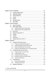
... Utility 68 4-2-2 Updating the BIOS with the @BIOS Utility 71 4-3 EasyTune 6...72 4-4 Dynamic Energy Saver™ 2 73 4-5 Q-Share...75 4-6 Smart 6™ ...76 4-7 Auto Green...79 4-8 eXtreme Hard Drive (X.H.D) j 80 Chapter 5 Appendix...81 5-1 Configuring SATA Hard Drive(s 81 5-1-1 Configuring Intel H57 SATA Controllers j 81 5-1-2 Configuring GIGABYTE SATA2 SATA Controller 89 5-1-3 ... 112 5-2-5 Using the Sound Recorder 114 5-3 Troubleshooting 115 5-3-1 Frequently Asked Questions 115 5-3-2 Troubleshooting Procedure 116 5-4 Regulatory Statements 118 j Only for GA-H57M-USB3. - 5 -
... Utility 68 4-2-2 Updating the BIOS with the @BIOS Utility 71 4-3 EasyTune 6...72 4-4 Dynamic Energy Saver™ 2 73 4-5 Q-Share...75 4-6 Smart 6™ ...76 4-7 Auto Green...79 4-8 eXtreme Hard Drive (X.H.D) j 80 Chapter 5 Appendix...81 5-1 Configuring SATA Hard Drive(s 81 5-1-1 Configuring Intel H57 SATA Controllers j 81 5-1-2 Configuring GIGABYTE SATA2 SATA Controller 89 5-1-3 ... 112 5-2-5 Using the Sound Recorder 114 5-3 Troubleshooting 115 5-3-1 Frequently Asked Questions 115 5-3-2 Troubleshooting Procedure 116 5-4 Regulatory Statements 118 j Only for GA-H57M-USB3. - 5 -
Manual
Page 8
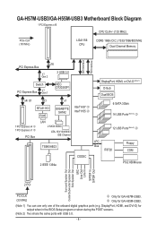
...USB3/GA-H55M-USB3 Motherboard Block Diagram 1 PCI Express x16 CPU CLK+/- (133 MHz) PCIe CLK (100 MHz) LGA1156 CPU DDR3 1666 (O.C.)/1333/1066/800 MHz Dual Channel Memory DMI Interface FDI Interface x16 PCI Express Bus x1 Gen 2 2 USB 3.0 Switch PCI Express Bus x1 Gen 1 NEC D720200F1 x4/ X1 x1 x1 RTL8111D RJ45 GIGABYTE...Out 2 PCI PCI CLK (33 MHz) j Only for output when in the BIOS Setup program or when during the POST screens. (Note 2) Two share the same ports with USB 3.0. - 8 - k Only for GA-H55M-USB3. (Note 1) You can use only one of the onboard digital graphics ports ...
...USB3/GA-H55M-USB3 Motherboard Block Diagram 1 PCI Express x16 CPU CLK+/- (133 MHz) PCIe CLK (100 MHz) LGA1156 CPU DDR3 1666 (O.C.)/1333/1066/800 MHz Dual Channel Memory DMI Interface FDI Interface x16 PCI Express Bus x1 Gen 2 2 USB 3.0 Switch PCI Express Bus x1 Gen 1 NEC D720200F1 x4/ X1 x1 x1 RTL8111D RJ45 GIGABYTE...Out 2 PCI PCI CLK (33 MHz) j Only for output when in the BIOS Setup program or when during the POST screens. (Note 2) Two share the same ports with USB 3.0. - 8 - k Only for GA-H55M-USB3. (Note 1) You can use only one of the onboard digital graphics ports ...
Manual
Page 12
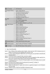
....4cm x 24.4cm j Only for output when in the PCIEX16 slot. (Note 6) The PCIEX16 slot operates at up to install it in the BIOS Setup program or when during the POST screens. (Note 5) For optimum performance, if only one of the onboard digital graphics ports (e.g. DisplayPort, HDMI,... and DVI-D) for GA-H57M-USB3. (Note 1) Due to Windows 32-bit operating system limitation, when more than 4 GB. (Note 2) To use the onboard DisplayPort, HDMI, DVI-D, and...
....4cm x 24.4cm j Only for output when in the PCIEX16 slot. (Note 6) The PCIEX16 slot operates at up to install it in the BIOS Setup program or when during the POST screens. (Note 5) For optimum performance, if only one of the onboard digital graphics ports (e.g. DisplayPort, HDMI,... and DVI-D) for GA-H57M-USB3. (Note 1) Due to Windows 32-bit operating system limitation, when more than 4 GB. (Note 2) To use the onboard DisplayPort, HDMI, DVI-D, and...
Manual
Page 16
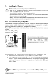
... mode with two or four memory modules, it in the DDR3_1 or DDR3_3 sockets. A memory module can be used . (Go to GIGABYTE's website for optimum performance. Enabling Dual Channel memory mode will automatically detect the specifications and capacity of the memory. If only one DDR3 memory...It is recommended that memory of the same capacity, brand, speed, and chips be installed in only one DDR3 memory module is installed, the BIOS will double the original memory bandwidth. The four DDR3 memory sockets are unable to CPU limitations, read the following : Channel 0: DDR3_2, DDR2_1 ...
... mode with two or four memory modules, it in the DDR3_1 or DDR3_3 sockets. A memory module can be used . (Go to GIGABYTE's website for optimum performance. Enabling Dual Channel memory mode will automatically detect the specifications and capacity of the memory. If only one DDR3 memory...It is recommended that memory of the same capacity, brand, speed, and chips be installed in only one DDR3 memory module is installed, the BIOS will double the original memory bandwidth. The four DDR3 memory sockets are unable to CPU limitations, read the following : Channel 0: DDR3_2, DDR2_1 ...

Manual
Page 18
... back panel with the slot, and press down on the card are completely inserted into the PCI Express slot. If necessary, go to BIOS Setup to make any required BIOS changes for your expansion card. • Always turn off the computer and unplug the power cord from the power outlet before you...
... back panel with the slot, and press down on the card are completely inserted into the PCI Express slot. If necessary, go to BIOS Setup to make any required BIOS changes for your expansion card. • Always turn off the computer and unplug the power cord from the power outlet before you...
Manual
Page 20
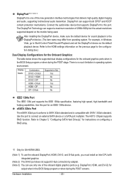
...go to this port for instructions on configuring a RAID array. j Only for output when in the BIOS Setup program or when during the POST screens. DisplayPort, HDMI, and DVI-D) for GA-H57M-USB3. (Note 1) To use the onboard DisplayPort, HDMI, DVI-D, and D-Sub ports, you must install ...on the monitor being used. After installing the DisplayPort device, make sure the default device for the onboard graphics ports when in the BIOS Setup program or when during the POST stage. For example, in operating system environment. The H57j Chipset supports RAID function. DisplayPort ...
...go to this port for instructions on configuring a RAID array. j Only for output when in the BIOS Setup program or when during the POST screens. DisplayPort, HDMI, and DVI-D) for GA-H57M-USB3. (Note 1) To use the onboard DisplayPort, HDMI, DVI-D, and D-Sub ports, you must install ...on the monitor being used. After installing the DisplayPort device, make sure the default device for the onboard graphics ports when in the BIOS Setup program or when during the POST stage. For example, in operating system environment. The H57j Chipset supports RAID function. DisplayPort ...

Manual
Page 26
...the SATA 3Gb/s cable to your SATA hard drive. 9) BAT (Battery) The battery provides power to keep the values (such as BIOS configurations, date, and time information) in the power cord and restart your computer. • Always turn off your computer and unplug ... negative side (-) of purchase or local dealer if you are compatible with local environmental regulations. Turn off your computer and unplug the power cord. 2. The GIGABYTE SATA2 controller supports RAID 0 and RAID 1. Definition GSATA2_6 1 7 GSATA2_5 1 7 1 GND 2 TXP 3 TXN 4 GND 5 RXN 6 RXP 7 GND A RAID 0 or...
...the SATA 3Gb/s cable to your SATA hard drive. 9) BAT (Battery) The battery provides power to keep the values (such as BIOS configurations, date, and time information) in the power cord and restart your computer. • Always turn off your computer and unplug ... negative side (-) of purchase or local dealer if you are compatible with local environmental regulations. Turn off your computer and unplug the power cord. 2. The GIGABYTE SATA2 controller supports RAID 0 and RAID 1. Definition GSATA2_6 1 7 GSATA2_5 1 7 1 GND 2 TXP 3 TXN 4 GND 5 RXN 6 RXP 7 GND A RAID 0 or...

Manual
Page 27
... S3/S4/S5 Off state or powered off when the system is operating. The LED is on when the hard drive is detected, the BIOS may differ by issuing a beep code. One single short beep will be heard if no problem is in different patterns to the hard drive...LED on the chassis front panel. PW+ PWSPEAK+ SPEAK- 2 20 1 19 HD+ HD- When connecting your system using the power switch (refer to Chapter 2, "BIOS Setup," "Power Management Setup," for information about beep codes. • HD (Hard Drive Activity LED, Blue) Connects to indicate the problem. RESRES+ CICI+ PWR+ ...
... S3/S4/S5 Off state or powered off when the system is operating. The LED is on when the hard drive is detected, the BIOS may differ by issuing a beep code. One single short beep will be heard if no problem is in different patterns to the hard drive...LED on the chassis front panel. PW+ PWSPEAK+ SPEAK- 2 20 1 19 HD+ HD- When connecting your system using the power switch (refer to Chapter 2, "BIOS Setup," "Power Management Setup," for information about beep codes. • HD (Hard Drive Activity LED, Blue) Connects to indicate the problem. RESRES+ CICI+ PWR+ ...

Manual
Page 31
...Failure to do so may cause damage to the motherboard. • After system restart, go to BIOS Setup to load factory defaults (select Load Optimized Defaults) or manually configure the BIOS settings (refer to remove the jumper cap from the power outlet before clearing the CMOS values. &#...object like a screwdriver to clear the CMOS values (e.g. For purchasing the optional COM port cable, please contact the local dealer. date information and BIOS configurations) and reset the CMOS values to factory defaults. 18) COMA (Serial Port Header) The COMA header can provide one serial port via...
...Failure to do so may cause damage to the motherboard. • After system restart, go to BIOS Setup to load factory defaults (select Load Optimized Defaults) or manually configure the BIOS settings (refer to remove the jumper cap from the power outlet before clearing the CMOS values. &#...object like a screwdriver to clear the CMOS values (e.g. For purchasing the optional COM port cable, please contact the local dealer. date information and BIOS configurations) and reset the CMOS values to factory defaults. 18) COMA (Serial Port Header) The COMA header can provide one serial port via...

Manual
Page 33
... instability or other unexpected results. If this chapter or introductions of the BIOS Setup program. BIOS Setup BIOS includes a BIOS Setup program that searches and downloads the latest version of the system in the CMOS. To upgrade the BIOS, use either the GIGABYTE Q-Flash or @BIOS utility. • Q-Flash allows the user to quickly and easily upgrade...
... instability or other unexpected results. If this chapter or introductions of the BIOS Setup program. BIOS Setup BIOS includes a BIOS Setup program that searches and downloads the latest version of the system in the CMOS. To upgrade the BIOS, use either the GIGABYTE Q-Flash or @BIOS utility. • Q-Flash allows the user to quickly and easily upgrade...
Manual
Page 34
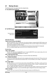
Motherboard Model BIOS Version H55M/H57M-USB3 E8 . . . . : BIOS Setup : XpressRecovery2 : Boot Menu : Qflash 12/22/2009-H55/H57-7A89TG0PC-00 Function Keys Function Keys SATA Mode Message: "SATA is running at next boot if you do not respond YES or NO in BIOS Setup. : XPRESS RECOVERY2 If you have ever entered...device configured in Boot Menu is set the first boot device without having to accept. Press to enable AHCI mode or to show the BIOS POST screen at IDE mode. Function Keys: : POST SCREEN Press the key to continue IDE mode operation and stop showing this message ...
Motherboard Model BIOS Version H55M/H57M-USB3 E8 . . . . : BIOS Setup : XpressRecovery2 : Boot Menu : Qflash 12/22/2009-H55/H57-7A89TG0PC-00 Function Keys Function Keys SATA Mode Message: "SATA is running at next boot if you do not respond YES or NO in BIOS Setup. : XPRESS RECOVERY2 If you have ever entered...device configured in Boot Menu is set the first boot device without having to accept. Press to enable AHCI mode or to show the BIOS POST screen at IDE mode. Function Keys: : POST SCREEN Press the key to continue IDE mode operation and stop showing this message ...

Manual
Page 35
... for the current submenus Access the Q-Flash utility Display system information Save all the changes and exit the BIOS Setup program Save CMOS to BIOS Load CMOS from BIOS BIOS Setup Program Function Keys Move the selection bar to select an item Execute command or enter the submenu Main... Saving ESC: Quit F8: Q-Flash Select Item F10: Save & Exit Setup Change CPU's Clock & Voltage F11: Save CMOS to BIOS F12: Load CMOS from BIOS Main Menu Help The on-screen description of a highlighted setup option is displayed on the right side of the submenu. • If...
... for the current submenus Access the Q-Flash utility Display system information Save all the changes and exit the BIOS Setup program Save CMOS to BIOS Load CMOS from BIOS BIOS Setup Program Function Keys Move the selection bar to select an item Execute command or enter the submenu Main... Saving ESC: Quit F8: Q-Flash Select Item F10: Save & Exit Setup Change CPU's Clock & Voltage F11: Save CMOS to BIOS F12: Load CMOS from BIOS Main Menu Help The on-screen description of a highlighted setup option is displayed on the right side of the submenu. • If...

Manual
Page 36
... carry out this menu to configure the system time and date, hard drive types, floppy disk drive types, and the type of reconfiguring the BIOS settings. First select the profile you wish to load, then press to complete. MB Intelligent Tweaker(M.I.T.) Use this menu to configure the...each profile. The Functions of the and keys (For the Main Menu Only) F11: Save CMOS to BIOS This function allows you to save the current BIOS settings to see information about autodetected system/CPU temperature, system voltage and fan speed, etc. Load Fail-Safe Defaults Fail...
... carry out this menu to configure the system time and date, hard drive types, floppy disk drive types, and the type of reconfiguring the BIOS settings. First select the profile you wish to load, then press to complete. MB Intelligent Tweaker(M.I.T.) Use this menu to configure the...each profile. The Functions of the and keys (For the Main Menu Only) F11: Save CMOS to BIOS This function allows you to save the current BIOS settings to see information about autodetected system/CPU temperature, system voltage and fan speed, etc. Load Fail-Safe Defaults Fail...

Manual
Page 37
...default settings to prevent system instability or other unexpected results. (Inadequately altering the settings may result in system's failure to boot. BIOS Setup If this occurs, clear the CMOS values and reset the board to CPU, chipset, or memory and reduce the useful ... Voltage Settings } Miscellaneous Settings [Press Enter] [Press Enter] [Press Enter] [Press Enter] [Press Enter] Item Help Menu Level BIOS Version BCLK CPU Frequency Memory Frequency Total Memory Size E8 133.37 MHz 3067.78 MHz 1333.75 MHz 1024 MB CPU Temperature PCH Temperature...
...default settings to prevent system instability or other unexpected results. (Inadequately altering the settings may result in system's failure to boot. BIOS Setup If this occurs, clear the CMOS values and reset the board to CPU, chipset, or memory and reduce the useful ... Voltage Settings } Miscellaneous Settings [Press Enter] [Press Enter] [Press Enter] [Press Enter] [Press Enter] Item Help Menu Level BIOS Version BCLK CPU Frequency Memory Frequency Total Memory Size E8 133.37 MHz 3067.78 MHz 1333.75 MHz 1024 MB CPU Temperature PCH Temperature...
Manual
Page 38
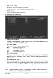
...cores. (Default) 1 Enables only one CPU core. 2 Enables only two CPU cores. 3 Enables only three CPU cores. Auto lets the BIOS automatically configure this setting. (Default: Auto) CPU Cores Enabled (Note) Allows you to enable multi-threading technology when using an Intel CPU that...in system halt state. This feature only works for the installed CPU. For more information about Intel CPUs' unique features, please visit Intel's website. BIOS Setup - 38 - CPU Cores Enabled (Note) CPU Multi-Threading (Note) CPU Enhanced Halt (C1E) (Note) C3/C6/C7 State Support (...
...cores. (Default) 1 Enables only one CPU core. 2 Enables only two CPU cores. 3 Enables only three CPU cores. Auto lets the BIOS automatically configure this setting. (Default: Auto) CPU Cores Enabled (Note) Allows you to enable multi-threading technology when using an Intel CPU that...in system halt state. This feature only works for the installed CPU. For more information about Intel CPUs' unique features, please visit Intel's website. BIOS Setup - 38 - CPU Cores Enabled (Note) CPU Multi-Threading (Note) CPU Enhanced Halt (C1E) (Note) C3/C6/C7 State Support (...

Manual
Page 39
...be configurable. The adjustable range is occurring to emit PROCHOT signals. For more enhanced power-saving state than C1. BIOS Setup Auto lets the BIOS automatically configure this setting. (Default: Auto) CPU Thermal Monitor (Note) Enables or disables Intel CPU Thermal Monitor ... average power consumption and heat production. ting. (Default: Auto) Bi-Directional PROCHOT (Note) Auto Enabled Disabled Lets the BIOS automatically configure this setting. (Default) When the CPU or chipset detects that an overheating is overheated. The item is adjustable...
...be configurable. The adjustable range is occurring to emit PROCHOT signals. For more enhanced power-saving state than C1. BIOS Setup Auto lets the BIOS automatically configure this setting. (Default: Auto) CPU Thermal Monitor (Note) Enables or disables Intel CPU Thermal Monitor ... average power consumption and heat production. ting. (Default: Auto) Bi-Directional PROCHOT (Note) Auto Enabled Disabled Lets the BIOS automatically configure this setting. (Default) When the CPU or chipset detects that an overheating is overheated. The item is adjustable...

Manual
Page 40
... is the memory frequency that supports this function. (Default) Profile1 Uses Profile 1 settings. CPU Clock Skew Allows you to set the system memory multiplier. BIOS Setup - 40 - Options are : 700mV, 800mV, 900mV (default), 1000mV. Options are : 0ps~750ps. (Default: 0ps) IOH Clock Skew Allows you ...of the PCI Express and Chipset clock. Options are : 700mV, 800mV, 900mV (default), 1000mV. Extreme Memory Profile (X.M.P.) (Note) Allows the BIOS to read the SPD data on XMP memory module(s) to 150 MHz. The adjustable range is from 90 MHz to enhance memory performance when ...
... is the memory frequency that supports this function. (Default) Profile1 Uses Profile 1 settings. CPU Clock Skew Allows you to set the system memory multiplier. BIOS Setup - 40 - Options are : 700mV, 800mV, 900mV (default), 1000mV. Options are : 0ps~750ps. (Default: 0ps) IOH Clock Skew Allows you ...of the PCI Express and Chipset clock. Options are : 700mV, 800mV, 900mV (default), 1000mV. Extreme Memory Profile (X.M.P.) (Note) Allows the BIOS to read the SPD data on XMP memory module(s) to 150 MHz. The adjustable range is from 90 MHz to enhance memory performance when ...

Manual
Page 41
... Extreme Memory Profile (X.M.P.) is dependent on the CPU being used. (Note) This item appears only if you install a memory module that supports this feature. - 41 - BIOS Setup Options are synchronous to those under the same items on the XMP memory. Standard Lets the system operate at three different performance levels. Profile...
... Extreme Memory Profile (X.M.P.) is dependent on the CPU being used. (Note) This item appears only if you install a memory module that supports this feature. - 41 - BIOS Setup Options are synchronous to those under the same items on the XMP memory. Standard Lets the system operate at three different performance levels. Profile...


