Manual
Page 4
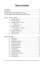
Table of Contents Box Contents...6 Optional Items...6 GA-H57M-USB3/GA-H55M-USB3 Motherboard Layout 7 GA-H57M-USB3/GA-H55M-USB3 Motherboard Block Diagram 8 Chapter 1 Hardware Installation 9 1-1 Installation Precautions 9 1-2 Product Specifications 10 1-3 Installing the CPU and CPU Cooler 13 1-3-1 Installing the CPU 13 1-3-2 Installing the CPU Cooler 15 1-4 Installing the Memory 16 1-4-1 Dual Channel Memory Configuration 16 1-4-2 Installing a Memory 17 1-5 Installing an Expansion Card 18...
Table of Contents Box Contents...6 Optional Items...6 GA-H57M-USB3/GA-H55M-USB3 Motherboard Layout 7 GA-H57M-USB3/GA-H55M-USB3 Motherboard Block Diagram 8 Chapter 1 Hardware Installation 9 1-1 Installation Precautions 9 1-2 Product Specifications 10 1-3 Installing the CPU and CPU Cooler 13 1-3-1 Installing the CPU 13 1-3-2 Installing the CPU Cooler 15 1-4 Installing the Memory 16 1-4-1 Dual Channel Memory Configuration 16 1-4-2 Installing a Memory 17 1-5 Installing an Expansion Card 18...
Manual
Page 8
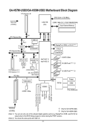
GA-H57M-USB3/GA-H55M-USB3 Motherboard Block Diagram 1 PCI Express x16 CPU CLK+/- (133 MHz) PCIe CLK (100 MHz) LGA1156 CPU DDR3 1666 (O.C.)/1333/1066/800 MHz Dual Channel Memory DMI Interface FDI Interface x16 PCI Express Bus x1 Gen 2 2 USB 3.0 Switch PCI Express Bus x1 Gen 1 NEC D720200F1 x4/ X1 x1 x1 RTL8111D RJ45 GIGABYTE... Setup program or when during the POST screens. (Note 2) Two share the same ports with USB 3.0. - 8 - DisplayPort, HDMI, and DVI-D) for GA-H57M-USB3. k Only for GA-H55M-USB3. (Note 1) You can use only one of the onboard digital graphics ports (e.g.
GA-H57M-USB3/GA-H55M-USB3 Motherboard Block Diagram 1 PCI Express x16 CPU CLK+/- (133 MHz) PCIe CLK (100 MHz) LGA1156 CPU DDR3 1666 (O.C.)/1333/1066/800 MHz Dual Channel Memory DMI Interface FDI Interface x16 PCI Express Bus x1 Gen 2 2 USB 3.0 Switch PCI Express Bus x1 Gen 1 NEC D720200F1 x4/ X1 x1 x1 RTL8111D RJ45 GIGABYTE... Setup program or when during the POST screens. (Note 2) Two share the same ports with USB 3.0. - 8 - DisplayPort, HDMI, and DVI-D) for GA-H57M-USB3. k Only for GA-H55M-USB3. (Note 1) You can use only one of the onboard digital graphics ports (e.g.
Manual
Page 9
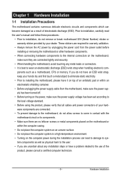
...; Do not place the computer system in a high-temperature environment. • Turning on the computer power during the installation process can become damaged as a motherboard, CPU or memory. ponents such as a result of electrostatic discharge (ESD). Hardware Installation Chapter 1 Hardware Installation 1-1 Installation Precautions The motherboard contains numerous delicate electronic circuits and...
...; Do not place the computer system in a high-temperature environment. • Turning on the computer power during the installation process can become damaged as a motherboard, CPU or memory. ponents such as a result of electrostatic discharge (ESD). Hardware Installation Chapter 1 Hardware Installation 1-1 Installation Precautions The motherboard contains numerous delicate electronic circuits and...
Manual
Page 10
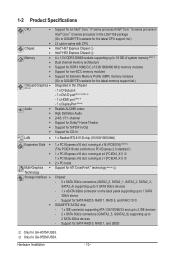
...for GA-H55M-USB3. Support for SATA RAID 0, RAID 1, RAID 5, and RAID 10 j w GIGABYTE SATA2 chip: - 1 x IDE connector supporting ATA-133/100/66/33 and up to 2 IDE devices - 2 x SATA 3Gb/s connectors (GSATA2_5, GSATA2_6) supporting up to 2 SATA 3Gb/s devices - Hardware Installation - 10 - 1-2 Product Specifications CPU w.../ Intel® Core™ i3 series processor in the LGA1156 package (Go to GIGABYTE's website for the latest CPU support list.) L3 cache varies with CPU Intel® H57 Express Chipset j Intel® H55 Express Chipset k 4 x ...
...for GA-H55M-USB3. Support for SATA RAID 0, RAID 1, RAID 5, and RAID 10 j w GIGABYTE SATA2 chip: - 1 x IDE connector supporting ATA-133/100/66/33 and up to 2 IDE devices - 2 x SATA 3Gb/s connectors (GSATA2_5, GSATA2_6) supporting up to 2 SATA 3Gb/s devices - Hardware Installation - 10 - 1-2 Product Specifications CPU w.../ Intel® Core™ i3 series processor in the LGA1156 package (Go to GIGABYTE's website for the latest CPU support list.) L3 cache varies with CPU Intel® H57 Express Chipset j Intel® H55 Express Chipset k 4 x ...
Manual
Page 11
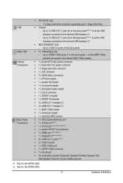
...USB3. Hardware Installation TSB43AB23 chip - Up to 2 USB 3.0 ports on the back panel, 1 via the USB brackets connected to the internal IEEE 1394a header) Internal w 1 x 24-pin ATX main power connector Connectors w 1 x 8-pin ATX 12V power connector w 1 x floppy disk drive connector w 1 x IDE connector w 7 x SATA 3Gb/s connectors w 1 x CPU... (Center/Subwoofer Speaker Out/Rear Speaker Out/ Side Speaker Out/Line In/Line Out/Microphone) j Only for GA-H55M-USB3. - 11 - Up to 1 floppy disk drive USB w Chipset: -
...USB3. Hardware Installation TSB43AB23 chip - Up to 2 USB 3.0 ports on the back panel, 1 via the USB brackets connected to the internal IEEE 1394a header) Internal w 1 x 24-pin ATX main power connector Connectors w 1 x 8-pin ATX 12V power connector w 1 x floppy disk drive connector w 1 x IDE connector w 7 x SATA 3Gb/s connectors w 1 x CPU... (Center/Subwoofer Speaker Out/Rear Speaker Out/ Side Speaker Out/Line In/Line Out/Microphone) j Only for GA-H55M-USB3. - 11 - Up to 1 floppy disk drive USB w Chipset: -
Manual
Page 12
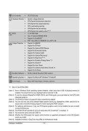
... (Note 8) 2 x 64 Mbit flash Use of the onboard digital graphics ports (e.g. Hardware Installation - 12 - j (Note 7) Two share the same ports with USB 3.0. (Note 8) Whether the CPU/system fan speed control function is installed, the actual memory size displayed will be sure to install it in the BIOS Setup program or when... the onboard DisplayPort, HDMI, DVI-D, and D-Sub ports, you install. (Note 9) Available functions in EasyTune may differ by motherboard model. DisplayPort, HDMI, and DVI-D) for GA-H57M-USB3. (Note 1) Due to x4 mode when ATI CrossFireX™ is enabled.
... (Note 8) 2 x 64 Mbit flash Use of the onboard digital graphics ports (e.g. Hardware Installation - 12 - j (Note 7) Two share the same ports with USB 3.0. (Note 8) Whether the CPU/system fan speed control function is installed, the actual memory size displayed will be sure to install it in the BIOS Setup program or when... the onboard DisplayPort, HDMI, DVI-D, and D-Sub ports, you install. (Note 9) Available functions in EasyTune may differ by motherboard model. DisplayPort, HDMI, and DVI-D) for GA-H57M-USB3. (Note 1) Due to x4 mode when ATI CrossFireX™ is enabled.

Manual
Page 13
... specifications, please do so according to your hardware specifications including the CPU, graphics card, memory, hard drive, etc. 1-3-1 Installing the CPU A. If you begin to install the CPU: • Make sure that the motherboard supports the CPU. (Go to GIGABYTE's website for the peripherals. 1-3 Installing the CPU and CPU Cooler Read the following guidelines before installing the...
... specifications, please do so according to your hardware specifications including the CPU, graphics card, memory, hard drive, etc. 1-3-1 Installing the CPU A. If you begin to install the CPU: • Make sure that the motherboard supports the CPU. (Go to GIGABYTE's website for the peripherals. 1-3 Installing the CPU and CPU Cooler Read the following guidelines before installing the...

Manual
Page 14
... to prevent damage to lightly replace the load plate. Hold your thumb to lift up the front edge (next to correctly install the CPU into the motherboard CPU socket. Hardware Installation - 14 - Follow the steps below to the "REMOVE" mark) and then remove the cover. (DO NOT touch... contacts. Step 2: Remove the CPU socket cover as well. Before installing the CPU, make sure the front end of the CPU socket (or you may align the CPU notches with your finger. To protect the CPU socket, always replace the protective socket cover when the CPU is properly inserted, use the ...
... to prevent damage to lightly replace the load plate. Hold your thumb to lift up the front edge (next to correctly install the CPU into the motherboard CPU socket. Hardware Installation - 14 - Follow the steps below to the "REMOVE" mark) and then remove the cover. (DO NOT touch... contacts. Step 2: Remove the CPU socket cover as well. Before installing the CPU, make sure the front end of the CPU socket (or you may align the CPU notches with your finger. To protect the CPU socket, always replace the protective socket cover when the CPU is properly inserted, use the ...

Manual
Page 15
... (The following procedure uses Intel® boxed cooler as the picture above shows, the installation is to install.) Step 3: Place the cooler atop the CPU, aligning the four push pins through the pin holes on the motherboard. Check that the Male and Female push pins are joined closely. (Refer to... your CPU cooler installation manual for instructions on installing the cooler.) Step 5: After the installation, check the back of arrow is to remove the cooler, ...
... (The following procedure uses Intel® boxed cooler as the picture above shows, the installation is to install.) Step 3: Place the cooler atop the CPU, aligning the four push pins through the pin holes on the motherboard. Check that the Male and Female push pins are joined closely. (Refer to... your CPU cooler installation manual for instructions on installing the cooler.) Step 5: After the installation, check the back of arrow is to remove the cooler, ...
Manual
Page 16
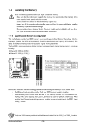
.../SS DDR3_3 DS/SS DS/SS (SS=Single-Sided, DS=Double-Sided, "- -"=No Memory) DDR3_2 DDR3_1 DDR3_4 DDR3_3 Due to CPU limitations, read the following guidelines before installing the memory to GIGABYTE's website for optimum performance. Dual Channel mode cannot be enabled if only one DDR3 memory module is installed, be sure...
.../SS DDR3_3 DS/SS DS/SS (SS=Single-Sided, DS=Double-Sided, "- -"=No Memory) DDR3_2 DDR3_1 DDR3_4 DDR3_3 Due to CPU limitations, read the following guidelines before installing the memory to GIGABYTE's website for optimum performance. Dual Channel mode cannot be enabled if only one DDR3 memory module is installed, be sure...
Manual
Page 20
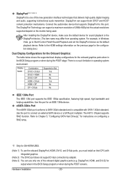
... to connect an external SATA device or a SATA port multiplier. After installing the DisplayPort device, make sure the default device for GA-H57M-USB3. (Note 1) To use only one of the new generation interface technologies that supports DisplayPort to this port for an IEEE 1394a ...20 - The H57j Chipset supports RAID function. DisplayPort can use the onboard DisplayPort, HDMI, DVI-D, and D-Sub ports, you must install an Intel CPU with SATA 1.5Gb/s standard. eSATA 3Gb/s Port The eSATA 3Gb/s port conforms to Chapter 5, "Configuring SATA Hard Drive(s)," for instructions on configuring a...
... to connect an external SATA device or a SATA port multiplier. After installing the DisplayPort device, make sure the default device for GA-H57M-USB3. (Note 1) To use only one of the new generation interface technologies that supports DisplayPort to this port for an IEEE 1394a ...20 - The H57j Chipset supports RAID function. DisplayPort can use the onboard DisplayPort, HDMI, DVI-D, and D-Sub ports, you must install an Intel CPU with SATA 1.5Gb/s standard. eSATA 3Gb/s Port The eSATA 3Gb/s port conforms to Chapter 5, "Configuring SATA Hard Drive(s)," for instructions on configuring a...

Manual
Page 23
.../Off) 5 GND 17 GND 6 +5V 18 GND 7 GND 19 GND 8 Power Good 20 -5V 9 5VSB (stand by the CPU manufacturer when using an Intel Extreme Edition CPU (130W). • To meet expansion requirements, it is used (500W or greater). Hardware Installation Before connecting the power connector, first make ... the motherboard. The 12V power connector mainly supplies power to the power connector in the correct orientation. Connect the power supply cable to the CPU. If the 12V power connector is not connected, the computer will not start. • Use of the power connector, the power supply...
.../Off) 5 GND 17 GND 6 +5V 18 GND 7 GND 19 GND 8 Power Good 20 -5V 9 5VSB (stand by the CPU manufacturer when using an Intel Extreme Edition CPU (130W). • To meet expansion requirements, it is used (500W or greater). Hardware Installation Before connecting the power connector, first make ... the motherboard. The 12V power connector mainly supplies power to the power connector in the correct orientation. Connect the power supply cable to the CPU. If the 12V power connector is not connected, the computer will not start. • Use of the power connector, the power supply...

Manual
Page 24
... it in damage to locate pin 1 of floppy disk drives supported are not configuration jumper blocks. Before connecting a floppy disk drive, be sure to the CPU or the system may hang. • These fan headers are : 360 KB, 720 KB, 1.2 MB, 1.44 MB, and 2.88 MB. For...not place a jumper cap on the headers. 5) FDD (Floppy Disk Drive Connector) This connector is typically designated by a stripe of a CPU fan with fan speed control design. The motherboard supports CPU fan speed control, which requires the use of different color. 3/4) CPU_FAN/SYS_FAN (Fan Headers) The motherboard has a 4-pin...
... it in damage to locate pin 1 of floppy disk drives supported are not configuration jumper blocks. Before connecting a floppy disk drive, be sure to the CPU or the system may hang. • These fan headers are : 360 KB, 720 KB, 1.2 MB, 1.44 MB, and 2.88 MB. For...not place a jumper cap on the headers. 5) FDD (Floppy Disk Drive Connector) This connector is typically designated by a stripe of a CPU fan with fan speed control design. The motherboard supports CPU fan speed control, which requires the use of different color. 3/4) CPU_FAN/SYS_FAN (Fan Headers) The motherboard has a 4-pin...

Manual
Page 32
Hardware Installation - 32 - To enable the Phase LED display function, please first enable Dynamic Energy Saver™ 2. Refer to Chapter 4, "Dynamic Energy Saver™ 2," for more the number of lighted LEDs indicates the CPU loading. The higher the CPU loading, the more details. 20) PHASE LED The number of lighted LEDs.
Hardware Installation - 32 - To enable the Phase LED display function, please first enable Dynamic Energy Saver™ 2. Refer to Chapter 4, "Dynamic Energy Saver™ 2," for more the number of lighted LEDs indicates the CPU loading. The higher the CPU loading, the more details. 20) PHASE LED The number of lighted LEDs.

Manual
Page 35
... Optimized Defaults Set Supervisor Password Set User Password Save & Exit Setup Exit Without Saving ESC: Quit F8: Q-Flash Select Item F10: Save & Exit Setup Change CPU's Clock & Voltage F11: Save CMOS to BIOS F12: Load CMOS from BIOS BIOS Setup Program Function Keys Move the selection bar to select an item...
... Optimized Defaults Set Supervisor Password Set User Password Save & Exit Setup Exit Without Saving ESC: Quit F8: Q-Flash Select Item F10: Save & Exit Setup Change CPU's Clock & Voltage F11: Save CMOS to BIOS F12: Load CMOS from BIOS BIOS Setup Program Function Keys Move the selection bar to select an item...

Manual
Page 36
...stop the system boot, etc. Advanced BIOS Features Use this menu to configure the device boot order, advanced features available on the CPU, and the primary display adapter. Integrated Peripherals Use this menu to configure all peripheral devices, such as IDE, SATA, USB, integrated...confirmation message will exit BIOS Setup. (Pressing can create up to the system and BIOS Setup. Pressing to see information about autodetected system/CPU temperature, system voltage and fan speed, etc. Load Fail-Safe Defaults Fail-Safe defaults are factory settings for the most stable,...
...stop the system boot, etc. Advanced BIOS Features Use this menu to configure the device boot order, advanced features available on the CPU, and the primary display adapter. Integrated Peripherals Use this menu to configure all peripheral devices, such as IDE, SATA, USB, integrated...confirmation message will exit BIOS Setup. (Pressing can create up to the system and BIOS Setup. Pressing to see information about autodetected system/CPU temperature, system voltage and fan speed, etc. Load Fail-Safe Defaults Fail-Safe defaults are factory settings for the most stable,...

Manual
Page 37
...Note 2) System Memory Multiplier (SPD) Memory Frequency (Mhz) 1333 Internal Graphics Clock 733 PCI Express Frequency (Mhz) >>>>> Advanced Clock Control CPU Clock Drive PCI Express Clock Drive CPU Clock Skew IOH Clock Skew [23X] 3.06GHz (133x23) [Press Enter] [Auto] 5.86GHz [Disabled] 133 [Disabled] [Auto] 1333...prevent system instability or other unexpected results. (Inadequately altering the settings may result in system's failure to CPU, chipset, or memory and reduce the useful life of these components. BIOS Setup Incorrectly doing overclock/overvoltage may ...
...Note 2) System Memory Multiplier (SPD) Memory Frequency (Mhz) 1333 Internal Graphics Clock 733 PCI Express Frequency (Mhz) >>>>> Advanced Clock Control CPU Clock Drive PCI Express Clock Drive CPU Clock Skew IOH Clock Skew [23X] 3.06GHz (133x23) [Press Enter] [Auto] 5.86GHz [Disabled] 133 [Disabled] [Auto] 1333...prevent system instability or other unexpected results. (Inadequately altering the settings may result in system's failure to CPU, chipset, or memory and reduce the useful life of these components. BIOS Setup Incorrectly doing overclock/overvoltage may ...
Manual
Page 38
...will be reduced during system halt state to enable the Intel CPU Turbo Boost technology. CPU Cores Enabled (Note) CPU Multi-Threading (Note) CPU Enhanced Halt (C1E) (Note) C3/C6/C7 State Support (Note) CPU Thermal Monitor (Note) CPU EIST Function (Note) Bi-Directional PROCHOT (Note) [Auto]...setting. (Default: Auto) (Note) This item is installed. CPU Frequency Displays the current operating CPU frequency. Advanced CPU Core Features CMOS Setup Utility-Copyright (C) 1984-2009 Award Software Advanced CPU Core Features Intel(R) Turbo Boost Tech. Auto lets the BIOS...
...will be reduced during system halt state to enable the Intel CPU Turbo Boost technology. CPU Cores Enabled (Note) CPU Multi-Threading (Note) CPU Enhanced Halt (C1E) (Note) C3/C6/C7 State Support (Note) CPU Thermal Monitor (Note) CPU EIST Function (Note) Bi-Directional PROCHOT (Note) [Auto]...setting. (Default: Auto) (Note) This item is installed. CPU Frequency Displays the current operating CPU frequency. Advanced CPU Core Features CMOS Setup Utility-Copyright (C) 1984-2009 Award Software Advanced CPU Core Features Intel(R) Turbo Boost Tech. Auto lets the BIOS...

Manual
Page 39
..., PROCHOT signals will allow for 20 seconds to allow the BCLK Frequency(Mhz) item below to 600 MHz. Only allows the CPU to detect whether an overheating is overheated. This item is configurable only if the Base Clock(BCLK) Control option is from 100... Bi-Directional PROCHOT (Note) Auto Enabled Disabled Lets the BIOS automatically configure this setting. (Default) When the CPU or chipset detects that the CPU frequency be emitted to lower CPU performance to manually set the QPI clock ratio. Important: It is highly recommended that an overheating is installed. ...
..., PROCHOT signals will allow for 20 seconds to allow the BCLK Frequency(Mhz) item below to 600 MHz. Only allows the CPU to detect whether an overheating is overheated. This item is configurable only if the Base Clock(BCLK) Control option is from 100... Bi-Directional PROCHOT (Note) Auto Enabled Disabled Lets the BIOS automatically configure this setting. (Default) When the CPU or chipset detects that the CPU frequency be emitted to lower CPU performance to manually set the QPI clock ratio. Important: It is highly recommended that an overheating is installed. ...

Manual
Page 40
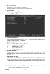
... to read the SPD data on XMP memory module(s) to adjust the amplitude of the CPU and Chipset clock. Auto sets the PCIe clock frequency to standard 100 MHz. (Default: Auto) >>>>> Advanced Clock Control CPU Clock Drive Allows you to set the Chipset clock prior to 150 MHz. Options are ...: 0ps~750ps. (Default: 0ps) IOH Clock Skew Allows you to enhance memory performance when enabled. CPU Clock Skew Allows you to the Chipset clock. System Memory...
... to read the SPD data on XMP memory module(s) to adjust the amplitude of the CPU and Chipset clock. Auto sets the PCIe clock frequency to standard 100 MHz. (Default: Auto) >>>>> Advanced Clock Control CPU Clock Drive Allows you to set the Chipset clock prior to 150 MHz. Options are ...: 0ps~750ps. (Default: 0ps) IOH Clock Skew Allows you to enhance memory performance when enabled. CPU Clock Skew Allows you to the Chipset clock. System Memory...


